Actually, trunk lift struts are the right way to approach the issue, but dont think of them as one leg of the restraint, think of them as a variable cross brace between a forward and aft legs. In their normal application they will hold the rear hatch open at zero speed, but slowly close as car speed is increased, since there is some load on the rear hatch. I dont think the current electric lift struts will work fast enough, but you may be able to over power them as the speed increases.
Like I told Saul Goode just Yesterday, And up post, an air Pump to activate a pair of Bags/Shocks W/a Coilover and an Air Bleed set up , something using parts from the LO-Rider crowd, Touch the Brakes and it rises the harder you push the pedal (Potentiometer) the Higher the 'wing" Raises the Coil spring can Modulate the Hight (Downforce) with spring Tension and the Air bleed allows it to Lay Back at a Rate that can be Adjusted with Air Release. I am Looking For REALLY Big numbers of Downforce Damn the Drag, It will Help in this case.
In reply to GTXVette :
Airbags will work very well for quick deployment of aero surfaces. For autocross, you would not need to do much more than close up any slot gap for a multi-element wing under braking, or tip a single-element wing closer to vertical (probably dropping the front edge instead of raining the rear). So using the airbags might need to be setup reverse of what you mentioned. air up for on the gas, and bleed down for braking. Either way can work, but one way may be easier to setup than the other.

Matt
New Reader
4/2/19 7:50 a.m.
stafford1500 said:
The next step is deformable aero. Let the wing lay back as the speeds increase to reduce drag and downforce. It may require a bit more engineering and testing, but the wing could be driven to it lowest drag position and still impart some donwforce for grip at the end of the 1/4 mile. Also dont loose sight of the ground effect I discussed earlier. The effects can become massive at low ground clearances.
I'm glad you mentioned this! i did this as a byproduct of my less-than-perfect manufacturing skills: when i made my wing, the tail kink detail of the foil was a challenge. it was not difficult to cut the profile into the ribs given i have a 14" chord length, however, when shaping the aluminum (.025" 2024 T3) to maintain that detail, it became clear that i was not going to get it perfect (FYI to DIYers: thin heat treated Alum is harder to roll than thicker stuff as it springs back a lot more). The very thin nature of the last 3 inches (flap section) of the wing negated any intercostal structure, and thus left it subject to flexion (although it is bonded well). Initially i was going to use the mount assy (note picture shows angle cut short to allow tail flex) and the end plates to support its shape at speed, but in the end it made sense to "let it go" and potentially reduce lift/drag at high speeds. documenting this deflection is part of my data collection goals for this summer.

Matt
New Reader
4/2/19 8:02 a.m.
In reply to GTXVette :
Close but not quite the same air bag use - my first wing prototype was a "bladder foil". The initial profile of my first wing, we will use S1223 as an example, was built using a periphery internal structure. i modified an implement inner tube to fill the center section of the wing and pumped it up to hold its shape. the natural shape of the wing was thinner than the proper profile and it would inflate to it’s designed shape, and then past that to wreck the functional shape at will... no need to have adjustable AoA, just pressure settings.
Matt
New Reader
4/2/19 8:21 a.m.
Robbie said:
In reply to maschinenbau :
- I also want to do a matching splitter. Splitter can create downforce AND reduce drag if I understand correctly. But making a challenge car additionally tail-happy at speed doesn't sound like a good autox setup. So if we first develop a wing to keep the rear stable at speed and then add the splitter to match, we might end up with same drag AND more downforce overall.
there should be a splitter thread...and aero-balance - i built a splitter and couldn't believe the difference at turn-in on 40mph corners, but i'd like a hand with it now i got the wing on
In reply to Matt :
bu bu bu But, Well , But what About ... Well , Yea I See it, Huh. Humm, Some Sliding Panels, Leading edge deicer is Already Tested, Huh
Why not just build flaps and have variable angle of attack, like an airplane?

Nugi
Reader
4/3/19 9:00 a.m.
Did I miss the part where these are being directly coupled to the suspension instead of pushing on the springs? Nope? Just checking. Nevermind. Terrible idea. Haha.
In reply to Nugi :
With ideas like that, you are going to get rules named after you and banned from series... :)

well - this javafoil applet is REALLY fun! thanks for pointing it out. For those who have not done it yet, go here: https://www.mh-aerotools.de/airfoils/javafoil.htm and play around a bit. If you are using a browser that has java enabled you might not have to install anything, if you aren't, then you might have to install a local copy of the applet. It allows you to build your own airfoil shapes and test them. (If anyone knows how to make it bigger however, I'm all ears. It is tiny on my screen.) Anyway, I made this:

I took sleepyhead's advice and played around with the leading and trailing edge a bit, trying to keep in mind shapes that would be easy to re-create with plywood. So the above is a cambered plate airfoil (5% thickness 20% camber), with 10 degrees AoA. I put what is essentially a roundover (use the router) on the bottom leading corner AND the top trailing corner. This seems to have increased the lift coefficient about 10% at the cost of about 3x the drag of the standard cambered plate. But the drag is still low and if I actually got a lift coefficient around 3.5 I would be floored. According to my math below, a lift coefficient of 3.5 would get me nearly 100 lbs of downforce at 35 MPH, and upwards of 300 lbs at the top end of an autox. The cool thing is when I test the wing I can use this table to approximate the actual lift coefficient of the wing I have built.

Because I had javafoil open however, I decided to see what I could do with an extra foil - here is the result (note zoomed out a bit):

I tried to make the additional airfoil with a similar thickness and roundovers, it just has a tighter bend. If I built an airfoil that actually performed like that we are now talking about some serious forces!
Note: both of the wings I built in javafoil show consistent performance in terms of Cl and Cd across the 400k to 900k reynolds number range, which is where I need the wings to work, so that is good.
I can also try to make my shapes a bit more accurate and then upload the coordinates to javafoil, so I think that would help the modeling.
Nugi said:
Did I miss the part where these are being directly coupled to the suspension instead of pushing on the springs? Nope? Just checking. Nevermind. Terrible idea. Haha.
Well, with our solid rear axle and gutted rear interior, this may not be out of the question! Can you give me details on the benefits?
I can understand that high downforce just puts you onto the bumpstops, meaning your suspension either needs to be really stiff at low speeds or really bump-stoppy under aero. Are there other advantages?
3.5 is do-able... but you're going to be using multiple elements. second element probably doesn't need to be cambered as much / at-all. should be about .1c "y" from the first element and at the end, or maybe back a little bit. start with it "angled to match the local angle at the traililng edge", and then you can probably add another 10deg.
*these are back of the napkin straight out of my head suggestions... I expect stafford will have better ones when he sees this
Robbie said:
Nugi said:
Did I miss the part where these are being directly coupled to the suspension instead of pushing on the springs? Nope? Just checking. Nevermind. Terrible idea. Haha.
Well, with our solid rear axle and gutted rear interior, this may not be out of the question! Can you give me details on the benefits?
I can understand that high downforce just puts you onto the bumpstops, meaning your suspension either needs to be really stiff at low speeds or really bump-stoppy under aero. Are there other advantages?
if you can mount the wing upright to the knuckle, then you're by-passing the suspension and applying the downforce directly to where it needs to be applied... without any of the complications of going through the suspension. the problem is, doing that tended to crack the knuckles, and send CAM cars flying into barriers at high speed, iirc

My first shot at aligning the second element in an assembly is to approximate the lower surface curvature of the first element carried out to the end of the second element. Basically continue the first element bottom shape with the second element. After that there is a good bit of tweaking the angle and fore/aft vertical placement to get the slot gap in the right range.
When you get it right the low pressure (blue in your plots) should continue from the leading edge of the first element out beyond the overlap of the two elements. There will be some over lap between the elements, since you are trying to use the suction peak of the second element to 'pull' the air a bit further around the first element and add energy to the lower flow so that the air can stay attached longer.
For the double element you built above, try the modify tab and adjust the 'Pivot' to the leading edge of the second element, then sweep in 3-5 degree increments and see what you get. You may also want to try changing the option at the bottom of the Options tab to 'Ground effect' and rerun the simulation (More CL, but you have to move the section away from the Y-axis, since the Y-axis represents the ground in those cases).
If you get crazy, model a 90 degree wicker on the trailing edge of your second element and see if you can get the low pressure to progress further along the bottom surface. It does not take a massive second element to really compound the effects. That is part of the reason that you see so many elements used in really high downforce applications. You could imagine the whole assembly is lots of little wing sections each taking a turn at redirecting the air. That leads to the basic representation of lift/downforce generation as a sum of circulations, which is the beginning of the deep end for aero (Kutta/Jukowski theorem). Once you get past 3 or four elements you are working with cascades, kind of like if you laid the inlet for a turbo charger impeelor out in s straight line rather than around a circle.
On the subject of attaching to the axle directly, you remove all of the compliance that make up a suspension, putting the downforce directly into the tire, rather than letting it get distributed across the chassis then resolved to the tires. This was done in the 60's and banned nearly immediately in F1 and Can-Am. Look to history for things that are banned and consider that they were banned not because of danger but because they jumped the competition level up two or three notches (sometimes for safety too).
Boy that escalated quickly...
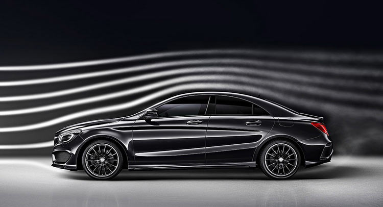
A quick question about ground effect and wing placement at the back of the car. Does a wing get ground effect from the top of the trunk lid acting as 'ground'? Let's assume that the flow stays mostly connected like the car in the picture below. I thought there might be a significant difference between ground moving relative to the wing or ground not moving relative to the wing.
Also, if we were to place a wing on the trunk of this car, then would the local angle of attack (and therefore the wing effective AoA) be downward at a 15ish degree angle?
Robbie said:
Also, if we were to place a wing on the trunk of this car, then would the local angle of attack (and therefore the wing effective AoA) be downward at a 15ish degree angle?
Yes
edit... it'll depend on how high from the trunk it is... and the angle of the back glass. You can see the angle is less the higher you go. And also, this is only really true in the center of the car. The angle will be closer to "free stream" ( i.e. ~0 deg) as you work your way out and beyond the side of the car.
the Daytona Coupe videos show this too; and shows that you can reduce the angle into the wing by placing a spoiler on top of the trunk... which can be useful if you're trying to balance the inflow angle across the wing span.
The ground effect is sort of true when discussing the trunk under a rear mounted wing. In the simulation, the ground is effectively moving at the same speed as the air in frestream, so no effective drag or flow variation at that limit. The trunk has some differential speed in relation to the air, so there is some drag impact. The wing/trunk can be considered a venturi of sorts.
Long story short the wing will be pulling up on the trunk and conversely the trunk is pulling down on the wing. The flow around the wing will be more like the ground effect model, but the lift/downforce numbers will be more like the free-stream results. Basically, the inflow to the wing will be affected by the car body and therefore must be accounted for. LIke SleepyHead noted the effect becomes smaller as you move away from centerline. However there is a real lateral flow that is not even considered in the 2D modeling. This inflow can change how the wing behaves, especially near the end plates where it can induce separation on the bottom surface, resulting in significantly less downforce.
Mounting a rear wing as far back as possible get over a big chunk of the "Biplane Effect" between the wing and trunk. However alot of series limit the overhang and due to that, mounting the wing higher is the next best solution. If you can mount the wing so that it just barely overhangs the body, it will act on the car like that flap acts on the first element fo a wing assembly. I will see if I can generate a simplfied car shape and a rear mounted wing to show the effects of wing position (and demonstrate the slot gap sensitivity mentioned above).
The variation in flow from centerline to the ends is the reason for the twisted shapes on most competition wings. The ends are angled to run near peak efficiency which is different than the conditions at centerline. On the S7 the centerline needed ~2degrees more nose up than the ends of the wing due to the long sloping engine cover. End plate shape can play a big part in this as well.

sleepyhead said:
Robbie said:
Nugi said:
Did I miss the part where these are being directly coupled to the suspension instead of pushing on the springs? Nope? Just checking. Nevermind. Terrible idea. Haha.
Well, with our solid rear axle and gutted rear interior, this may not be out of the question! Can you give me details on the benefits?
I can understand that high downforce just puts you onto the bumpstops, meaning your suspension either needs to be really stiff at low speeds or really bump-stoppy under aero. Are there other advantages?
if you can mount the wing upright to the knuckle, then you're by-passing the suspension and applying the downforce directly to where it needs to be applied... without any of the complications of going through the suspension. the problem is, doing that tended to crack the knuckles, and send CAM cars flying into barriers at high speed, iirc
That's called Un-sprung aero and it is illegal for most (all?) sanctioning bodies. As far as I know, it hasn't been tried since the 60's (i.e. the early days of aero on cars). I'd be really curious to try it on in an Auto-X application.
In reply to fanfoy :
theoretically... I think #Gridlife's rules are currently loose enough to allow it... certainly in Super Unlimited, and Unlimited. Track and Street Mod... it kind of depends on your interpretation of the technical glossary's definition of "wing" and "active aero"
Alright I said I would knock something together with a car in it so here you go, with a little extra data to help get the point across.
The pictures are pretty self explanatory (no wing, wing over trunk, and wing over-hanging trunk). All the flow is shown at car centerline (thus no wheels).
Note that the front balance shifts pretty quickly from nose-heavy to tail-heavy (just in downforce). I have seen production cars that show more than 100% front downforce (rear lift) in the wind tunnel and I have seen cars that try to blow-over too (very light front downforce). If you take that sort of trend and add it to your static and dynamic inertial loads (weight, acceleration/braking) you can get some pretty interesting chassis responses. That should keep everyones heads busy overnight.
That is a pretty sweet Mercury Zephyr/Chrysler K-car I doodled up in 30 seconds too.
The take-away for the rear wing position is to note how much the low pressure behind the car changes between a wing mounted over the trunk and over-hanging the rear bumper. Also not how much the stream lines at the leading edge of the wing change (less likely to be install the further back you move the wing), also higher pressure (less low) on the trunk.

I am surprised this went almost an entire day without some sort of comment
I thought about making a joke... or generating my own "k car" with a saw tooth bottom to "better represent a car's underbody"... or generating a "hatchback" version, since I expect that would be helpful for Matt and Robbie...
but, I need to back off a bit from running analysis... and devote more time for the next 4 weeks to getting some sim/video time to be ready for OneLap. So, I'm going to check out for now, and just keep my eye on this. I do appreciate the pointers you've given me... and the motivation to dig in to javafoil... I can see that that will pay some dividends, which hopefully I can plow back in to be helpful to others here


