


I'm picking up the tub tomorrow and dropping it right on the frame. Wish me luck.

I'm picking up the tub tomorrow and dropping it right on the frame. Wish me luck.

In reply to JoeTR6 :I've done both paid for sand blasting and done my own
you need a monster big air compressor to do a decent job and need to select the right abrasive media
plus the equipment you wear is heavy and hot and nasty plus you'll need a great respirator or fresh air supply or risk lung disease unpleasant to work in Not to mention it takes a really long time to do a perfect job
as far as removing blasting media (sand in most cases) the only way is mount the parts on a rotisserie and use pressurized air to blast and a good shop vac to suck
then leave it for a day or so and go at it again you'll get 90% of it the first time 90% of the remaining the second time 9o % etc etc in other words spend a week and there will still be a few grains of sand left
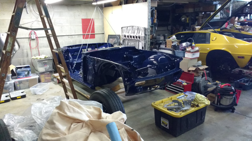
I stopped by after work to get the body ready to lift onto the frame. I didn't have a spotter to help guide the shell down, so didn't think it wise to attempt a landing on the frame. The balance with the new lift cables is really good and it only touches the paint where the bottom door hinge mounts, so it was worth the $30 in hardware.
The hood and trunk lid go to the painter tomorrow.
I'm on vacation next week, so have some time to contemplate the latest decision.
I've decided to put the fuel pump in the tank. One kit gives me an in-tank windage tray, fuel pump mount, and return port all in one easy to seal hole. It also cools the pump. I just need to add a high-pressure filter mounted vertically on the supply line next to the tank and a vapor return line. The question is where to add the vapor return. The left side frame rail is rather crowded, and the lines are somewhat tight going through the rear gearbox mount. I could easily run the plastic vapor return down the right rail. but it's fairly close to the exhaust. Even worse if I move the fuel return line to that side, but doing so would eliminate some potential rubbing issues. Whatever I do, the extra line is going through the factory hole on the right side of the tub that is normally just blocked with a rubber plug.
I may also add a flex fuel sensor in an attempt to milk a few extra HP out of this beast.
Yesterday the fuel return line was extracted and moved to the right side. The routing works out great except for heat from the exhaust. It runs about 2 inches from the exhaust through the cruciform area of the frame. I could make some heat shields out of aluminum, but was thinking that thermal heat shield sleeving might work better. I could slip it over the tubing before putting the AN fitting on and heat shrink the ends. This would also protect the line from chaffing. If not sufficient, I could add some metal plate heat shielding later. BTW, both the supply and return lines are 3/8" stainless steel.

Sounds like a solid plan, and how ive dealt with similar problems in the past. 2 inches, that far from the manifolds, shouldn't cause any issue with heat transference.
I took some time off work today to get the frame ready for the body. This mostly meant reinstalling the fuel lines with the insulating sleeve. The vapor vent line was put in basically where the fuel return line used to be, but it's smaller and was routed above the rear transmission mount. Here's what the fuel return line looks like now at the closest point to the exhaust.
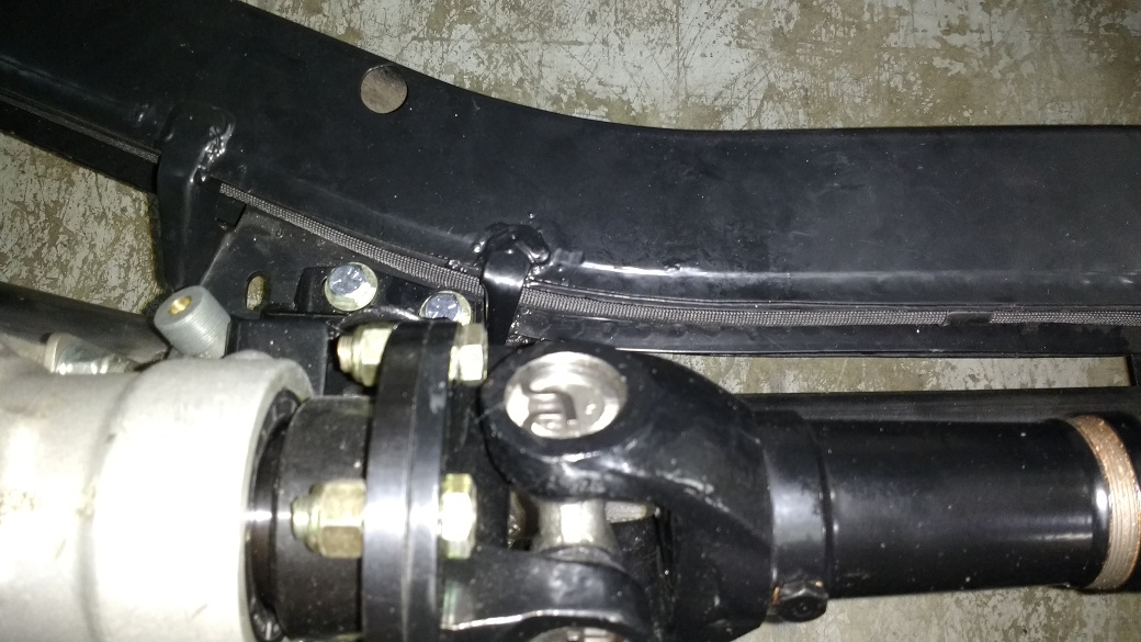
There is only little more than an inch of separation from the exhaust here, so I put a 1/2" sleeve over the 3/8" one in that area.
Hopefully Sunday will be the final joining.
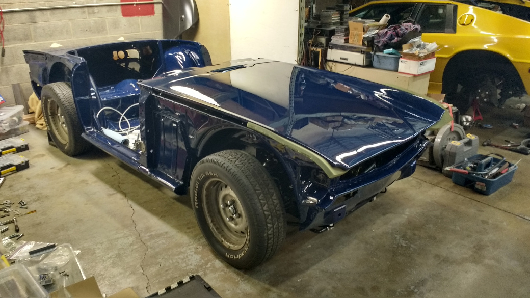
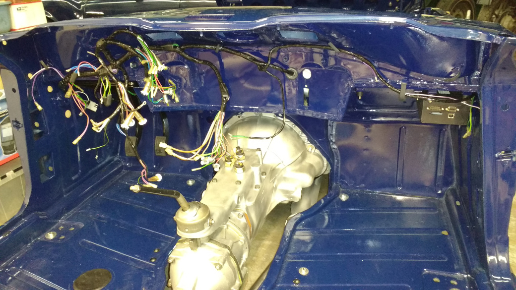
The body is on the frame. There are just a few bolts holding it on at the moment, but I can't fully bolt it down until the fenders and doors are on so that the gaps can be adjusted.
As a bonus, I picked up the bonnet and trunk lid today.
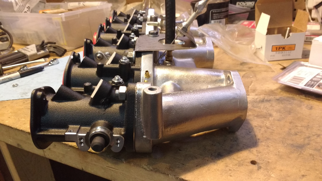
In other news, I received three Jenvey throttle bodies on Friday and am working on adding vacuum and cold idle ports to the intake manifold. The main problem now is that there are several (too many) things that need work, such as the pedal box and wiring. I also need to order a complete grommet set.
I picked up all of the hinges from the painter today and stopped by to install the bonnet hinges. I quickly realized this wasn't going to work since none of the threads have been cleaned up with a tap and my taps were at home. So I spent some time organizing parts and found a few things I didn't know I had. For instance, there was a complete grommet set and a bonnet catch with the safety lever (which appears to be no longer available new). After the hinges are bolted up, I really need to sort parts that I have in a way that makes sense to avoid spending hours looking for them or ordering duplicates.
This is absolutely beautiful!
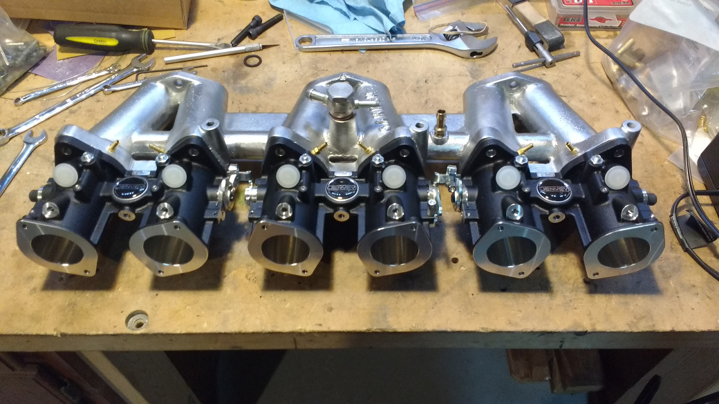
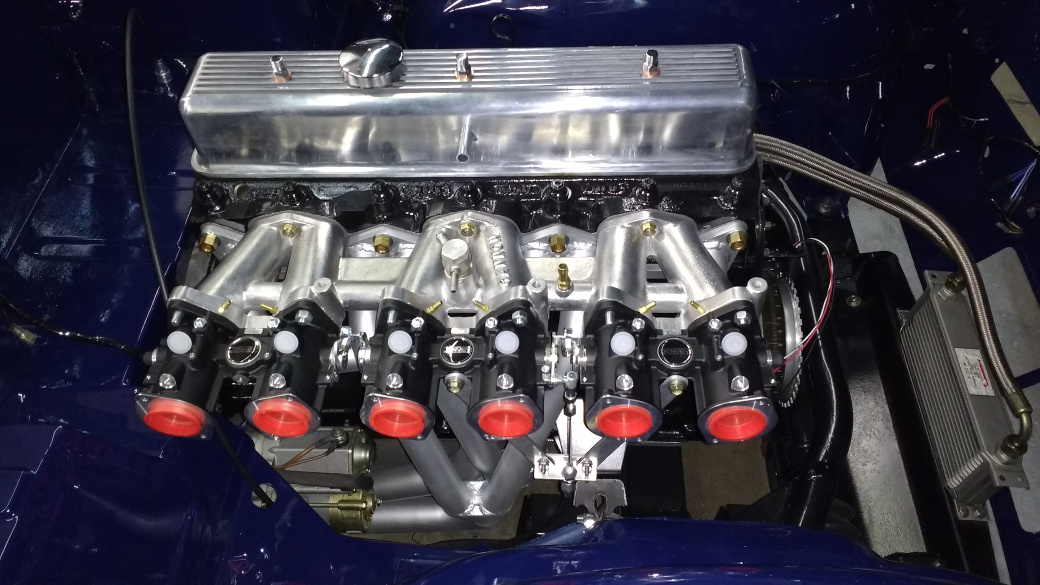
I've been working on the intake this week. The Jenvey throttles fit the manifold without too much trouble. Unfortunately, the mounting bolts that came with them are metric and I need 5/16"-20. Bolts won't even fit into the upper holes because of the injector bungs, so I'll use studs instead.
MAP ports were added to the intake on the throttle mounting flanges. Also, I drilled and tapped a boss that was on the balance tube for a cold start port. The only thing left to figure out is how to mount the throttle cable. The lever is between the second and third throttle and looks like it should be pulled almost vertically upwards. There's another lever that could be pulled from the bottom, but cable routing and exhaust heat makes that my second choice. Looking at this picture, I think my best option is to make a tripod that mounts to the boss between the throttle tubes and the intake boss for the throttle shaft (which I won't have). There are also unused mounting holes for a TPS where the throttle shaft exits that I may be able to use.

Ooooh, pretty

Wow, that intake setup is beautiful.
It will be a whole lot better looking when there's fuel and air running through it. ![]()
I struck out today trying to find 1 1/4" studs to hold the throttles on. Time to try making my own from some of the hardware shipment I got yesterday.
It turns out that tapping threads on stainless steel is hard. So much for making my own studs that won't rust.
My next problem is that I ordered 1 1/2" studs instead of 1 1/4". They are annoyingly long, but will hold the throttles on. I could cut them down, but they'll rust on the ends. Maybe I'll save these for the next time I replace trailing arm studs and actually get the right length this time. ![]()
I did manage to install the bonnet and trunk hinges without scratching any paint. The fit turned out really nice. Now I need to focus on getting this thing running. Sorting the intake manifold is first, but I also need to start working on the electrical fuse/relay panel and how I'm going to mount the cam sensor. I'd like to put the cam sensor on the timing chain cover and eliminate the distributor body completely, but that means I'll need to go with an electronic tach. I wonder if anyone makes generic tach guts that can be adapted to the stock TR6 tach housing?
I actually got to wrench on the car today. The pedal box was powder coated last weekend, so I bolted it in. Then the wiring harness was threaded through some holes and fastened down. This is a brand new harness that came with the car.
The Megasquirt was mounted using lord mounts to some tabs that I welded onto the tub. This should reduce the vibration it gets somewhat. I'm working on the fuse panel/relay board to go in next to the Megasquirt. I'm also working on a throttle cable bracket and should get the intake with throttles installed soon.
Hopefully my MSM will behave and stop taking time away from this project. Otherwise, it's time for a new daily driver.
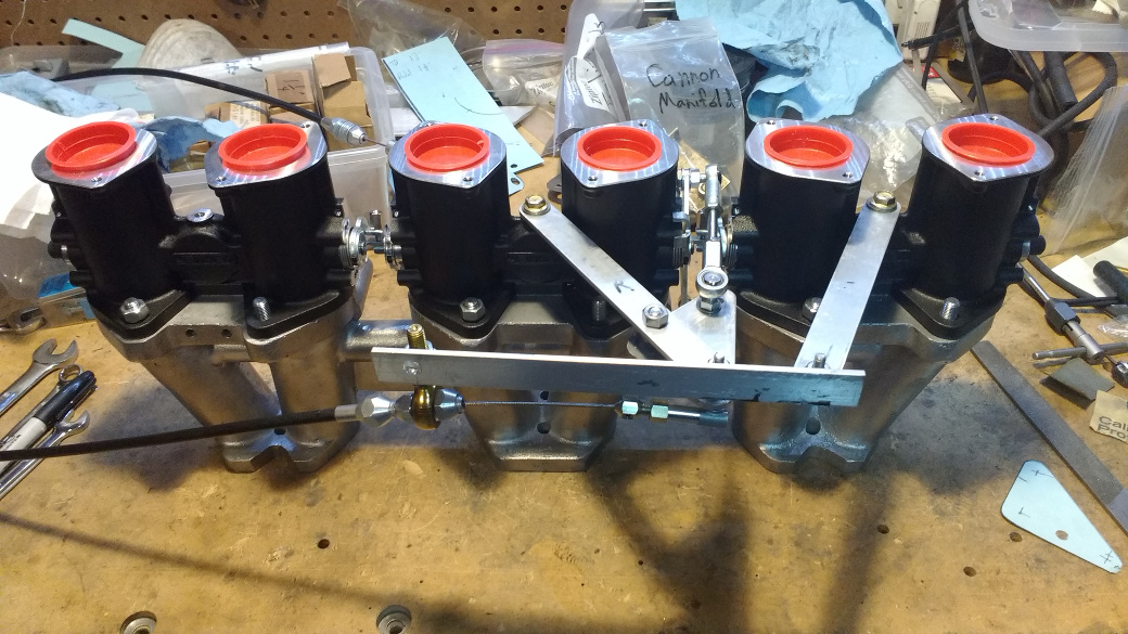
I made an attempt to work out the throttle cable bracket tonight. I'm not entirely happy with it.

The hose sticking out next to the cable goes to the idle air port. Unfortunately, there was one boss on the balance tube that I thought would be the best place to put it, but it's awfully close to where the throttle cable needs to be. A 90 degree elbow (that I didn't have) may fit under the bracket and the hose could be routed to the left.
I was originally going to pull the throttle straight up, but decided to avoid the tight bend in the cable from missing (or not) the bonnet. So I made a boomerang shaped thing so that the throttle could be pulled at a 45 degree angle. Here's how it looks from the side.
The bracket is heavy enough that it doesn't flex, but then again, it looks kind of heavy. An alternative is to thread some heim joints where they usually go when using Webers and run a pivot through them, then use bellcranks and pushrods. That's more complicated and looks more cluttered than this setup.

Or you could run a pulley that the cable would break over Not suggesting it but it would let you pull straight up and should be pretty easy to do

Rather than locking the end of the lockar cable with a fixed mount, consider including some freedom of movement by adding a heim joint to the design. This would keep the cable in proper alignment with the throttle lever and give a more linear pedal feel

NOHOME said:Rather than locking the end of the lockar cable with a fixed mount, consider including some freedom of movement by adding a heim joint to the design. This would keep the cable in proper alignment with the throttle lever and give a more linear pedal feel.
Interesting. I could drill a hole in the webbing next to the balance tube and mount one of these. It wouldn't by itself give me a 45 degree angle, so I would need to make a small bracket to hold it. With the current setup, the cable does travel through an arc and contacts the side of the cable housing at the limits of travel. This would improve that situation. I'd prefer to bolt a pulley to the throttle shaft than use the lever setup on there now. But it's easier to adjust the range of travel with a lever by drilling another hole. Once I've figured out the right ratio (the pedal end is set), the lever could be converted to a pulley.
I had a different idea for routing the throttle cable. Rather than pull from the top, I could pull straight down. I made a bracket out of aluminum that bolts to unused predrilled bosses on the throttles. This routes the cable across the back of the engine and fairly close to the exhaust header. Like this.
This may cook the throttle cable housing even if I wrap it in some of the insulating sleeve used for the fuel lines. OTOH, it may be fine and hides the cable. It also bends the cable through two 180 turns instead of just two 90 degree turns.
Another problem with this is that the throttle lever used is longer (1.5" vs 1.25") than the other lever and the throttle body blocks simply drilling a new hole to shorten it. With the setup above, the pedal only goes a little more than halfway to the floor. Even the shorter throttle lever gives too much rotation for the available cable pull. The problem is really with the aftermarket pedal. I think the lever on it is simply too long, and it's non-adjustable. The cable only moves 2" from closed to full throttle, but the pedal can provide 3.5" of travel. I think the stock pedal would give about the right amount of throw. Maybe I'll play around with that, as there appears to be enough room behind the engine for it (barely).
No matter what you do, it cant be as bad as the rube-goldberg system on the Healey 100-4 that I had to sort out. The drawing is wrong and the linkage was not working as designed when the car arrived.

NOHOME has given me some ideas for how to make this work better (as was perhaps not his intention) by making the throttle linkage *more* like that of an Austin Healey 100-4. The problem I'm facing is that the lever on the throttle and the accelerator pedal are different ratios. Even if I use the stock pedal and lever, I'll need to slightly change the ratio. If I add a bellcrank below the throttles, the cable can approach horizontally, eliminating that ugly 180 degree turn near the header. This also allows me to convert the linkage ratio to whatever I need. I've ordered some heim joints to hold the cable ends. If I go with the stock accelerator pedal, the lever will be on the firewall immediately behind the intake. It would be fairly simple to make a bracket to hold the heim joint at the proper angle and bolt that to the body. This would keep the cable very short and straight, but still allow the engine to rotate without affecting the throttle. Everything stays tucked away, but adjustments won't be too hateful.
You are welcome. ![]()
The throttle on the Healey probably took ten hours of head scratching and internet figuring before I figured out that the lever on the throttle pedal shaft and the bell-crank at the engine end were reversed/mirrored. What confounded me was that it worked as delivered, but it did not work as intended.
Of course, since the "repair" took all of 15 minutes, that is all I got to bill for![]()
This should be the final incarnation of the throttle linkage.
It probably wouldn't impress Donald Healey much, but it's good enough and solves my pedal ratio problem. Of course I could have just extended the lever on the pedal, but what's the fun in that? The bellcrank is slightly longer on one end to provide full throttle with 1.75" of cable travel. The stock pedal can do 2" without any throttle stop, but there is a bolt in the firewall limiting travel. I can use this to make the pedal bottom out just before the throttles are fully open.
The other thing done today was welding brackets on an aluminum radiator to hold a fan.

This is a $200 Chinese radiator and a $90 Spal fan. I'm hoping it doesn't spring a leak immediately. The drain tap that it came with was a wing bolt with a slot cut into it to let coolant gush out in some random direction. I retapped the threads for 1/4" NPT to use a better draincock that won't need to unthread from the aluminum bung.
You'll need to log in to post.


