
JoeTR6
HalfDork
7/16/16 10:20 a.m.
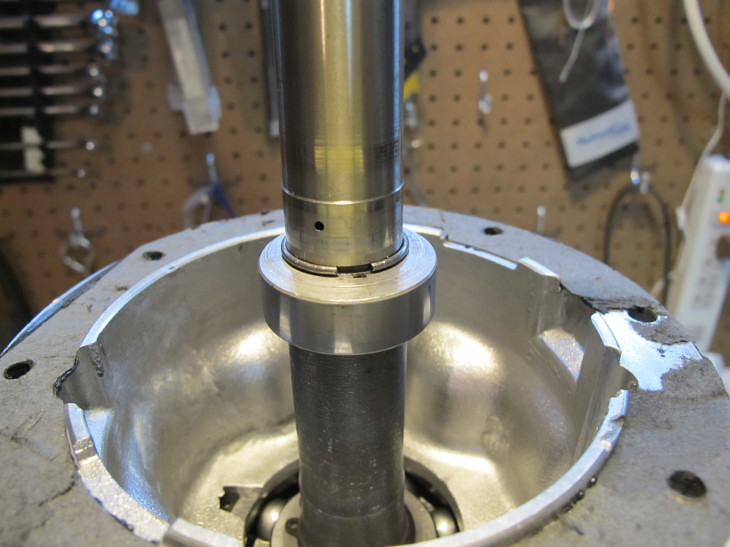
I've been whittling away on the gearbox. The first issue was pulling the overdrive back off to slip a spring clip over the end of the mainshaft to hold the oil pump cam in place. It turns out I had the clip, but didn't lay it out with the other parts. Here it is installed.
Separating the overdrive took some careful force, and I eventually ended up cutting/splitting the gasket with an X-acto knife.
The next issue was rebuilding/fitting the top cover. Getting it cleaned up and assembled wasn't too hard.
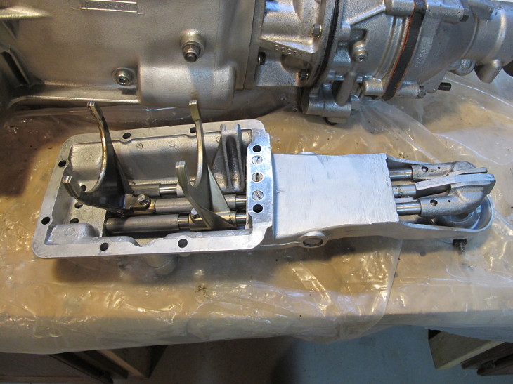
The trouble came from the new 1st/2nd shift fork. It looks nice, but after I bolted on the cover there was drag between the input and output shaft when in neutral. Shifting into 3rd or 4th resulted in some significant resistance. Based upon the ratio of input to output shaft turning when in neutral, it appeared the second gear synchronizer was binding. Replacing the 1st/2nd shift fork with a good used one fixed the problem. Here's what the new shift fork looked like from just turning the input shaft by hand several times.
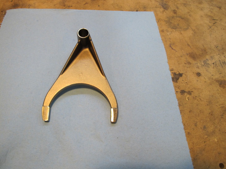
Disappointing. Maybe it's bent, but more likely an imprecise casting job. It might eventually have worn in, but not before the synchronizer ring was toast.
Cleaning off the gasket took some work. Before I remounted the overdrive, I checked the overdrive sump for debris and put a fresh gasket on the sump cover. A new overdrive gasket with a coating of silicone sealer, bolt on the top cover, and it's done. Hopefully it won't leak too badly.
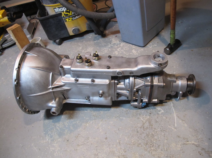
Oh, and three brand new Lucas interrupter switches. You know, for reliability.
What did you use to clean the outside of the trans case?
JoeTR6
HalfDork
7/16/16 4:58 p.m.
Jerry From LA wrote:
What did you use to clean the outside of the trans case?
Glass beads, a wire brush, and lots of air.
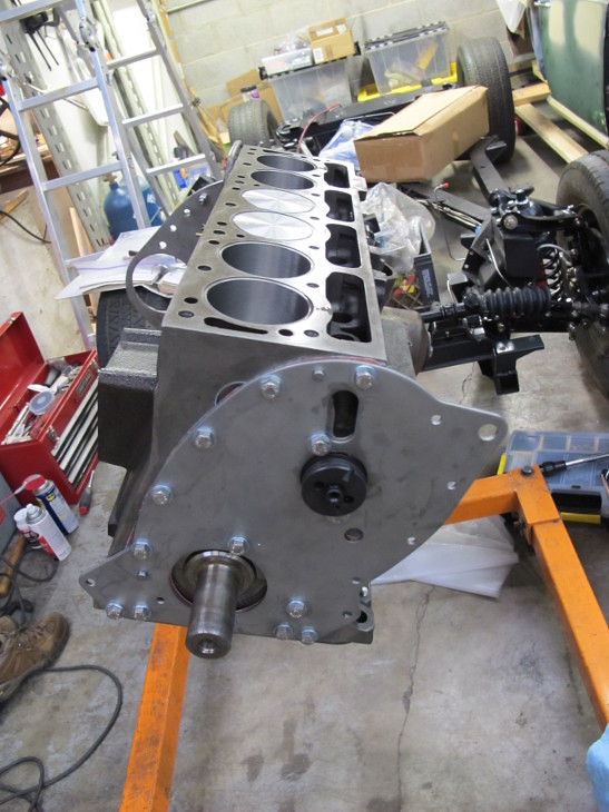
Hell must be a little colder today because I finally got the short block back. It looks good except for the iron being a bit seasoned. It's been almost 4 months since it was hot tanked.
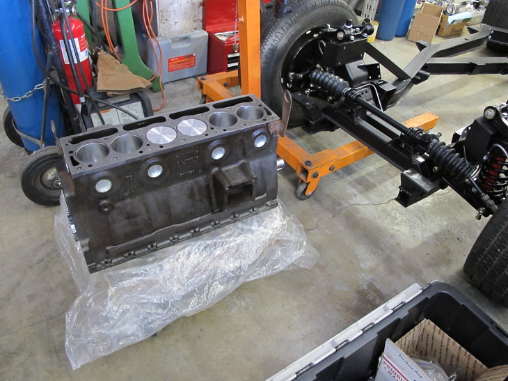
After moving stuff around to clear an area to work, I started by putting the rear crank seal on. It's going on a stand after checking the crank end float.
Por15 engine paint. That E36 M3 is indestructible.

NOHOME
PowerDork
7/17/16 8:40 p.m.
Dusterbd13 wrote:
Por15 engine paint. That E36 M3 is indestructible.
Is POR 15 engine paint not just POR 15?
It's glossier, comes in different colors, and goes on different. Unsure on chemical differences.
JoeTR6
HalfDork
7/18/16 4:56 p.m.
Thanks for the tip. Amazon has a pint of black POR 15 engine enamel for around $30. From what I've read, the block "must be free of grease, oil, grit, rust, and other foreign material that might impede proper adhesion". There's certainly lots of oil and rust to remove. Wire brushing and liberal use of brake cleaner should do the job.
When I was rebuilding the gearbox top cover, I used one from a TR3 which had interrupter switch holes on all forward gears (and I added one for reverse). This will let me engage the overdrive in 2nd gear. From the factory, J-type overdrives only worked in 3rd and 4th, but the earlier A-type overdrives also worked in 2nd. I've read the J-type is both stronger and weaker than the A-type, but it seems the primary reason it wasn't used in 2nd is that the oil pump is driven at drive shaft speed without a pressure accumulator (which the A-type had). It probably just shifted too slow at lower speeds. Since I'll only be using the overdrive in 2nd at autocross, I should be going around 50-55 MPH when engaging it. I just hope the planet gears remain in orbit.
JoeTR6
HalfDork
7/31/16 7:11 p.m.
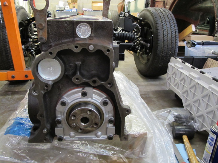
Today I bead blasted the engine end plates and cross-member tube. That was a sweaty job. After toweling off, I mounted the short block on a stand and checked the crankshaft end float. It was perfect at 0.006". Then I began sorting out the engine parts. The original aluminum front sealing block is missing. I'm replacing it with a steel one anyway, but didn't have the special bolts to fit it. Some socket bolts should do the job, but I didn't have any. So basically not much got done.
My brothers and I have been dealing with aging parent issues recently and that has taken priority over getting the engine put together. I'm going to try to spend a couple of hours after work this week getting things rolling again.
JoeTR6
HalfDork
8/5/16 8:31 p.m.
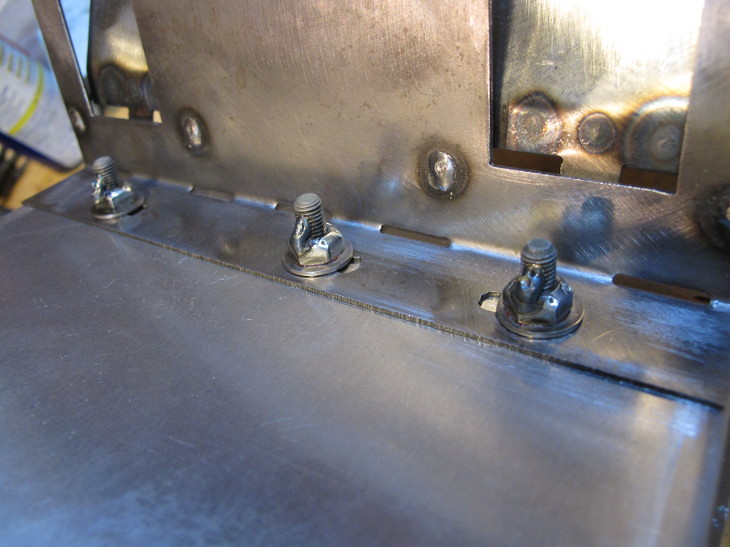
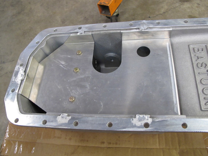
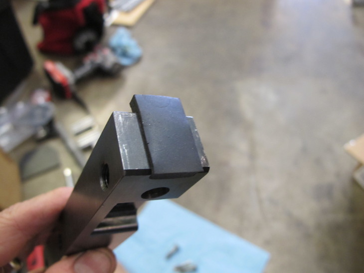
I got the oil pan ready to bolt up this week. The one I bought came with a windage tray, but I wanted to keep oil from sloshing to the back (the right in photo) under acceleration. I had a bulkhead with the one-way doors for a stock oil pan, but it wasn't deep enough for the new pan. Nothing a welder and angle grinder can't fix.
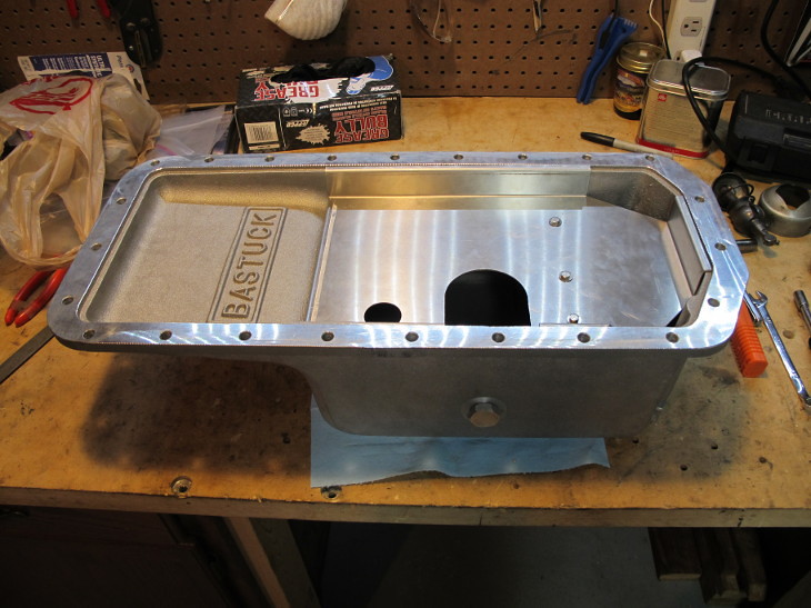
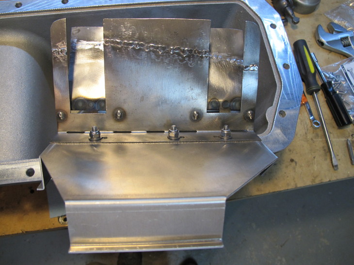
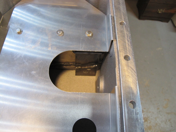
This gives an indication of how much deeper the new pan is. It's supposed to hold an extra quart of oil. The windage tray is aluminum and the bulkhead steel, so I couldn't weld it together. I'm going with stainless hardware with nyloc nuts and red loctite.
Engine assembly continues tomorrow.
Stupid question, but why nuts and bolts vs pop rivets?
JoeTR6
HalfDork
8/5/16 9:29 p.m.
I'll admit to having doubts about the bolts. Large steel pop rivets with washers may be the better way to go. I also considered welding some aluminum over the bolt heads just to keep them contained.
Ok. I was just wondering if there was some kind of advantages to the nuts and bolts vs pop rivets. In my head, pop rivets would be safer in the long run.
But again, I honestly don't know. That's why I asked. So I could learn something new today.
JoeTR6
HalfDork
8/6/16 7:53 a.m.
Over time, the nylon and loctite may degrade from the hot, dirty oil bath. The more I think about this, I want some sort of mechanical locking nut. Something like this.
Flexloc nuts
The real problem with pop rivets is the size required. I'm using #10 hardware (the holes were pre-drilled in the bulkhead). Aluminum rivets would be too soft and I'd need to eats me spinach to pop steel rivets that large. I'm also worried the vibration may fatigue them over time. But I'm a physics/computer nerd, not an engineer.
JoeTR6
HalfDork
8/6/16 6:41 p.m.
I bought some solid metal locking nuts, but decided to use the extra strength loctite anyway.
Two issues surfaced when I did a test fit of the oil pan. First, one of the front corners lifts away from the block by 0.040". We considered chucking it in a mill and leveling the flange, but couldn't come up with a decent way to clamp it down. Two bolts at opposite corners pulls it down easily, so I doubt this will distort the block and should seal with only a single gasket. The other problem is that the windage tray isn't held down tight by the block. The reinforcing gussets sort of keep it in place, but it's free to move vertically by almost 1/4". I considered gluing it in place with adhesive sealer, but 5 aluminum tack welds should hold it better semi-permanently.
JoeTR6
HalfDork
8/9/16 5:06 p.m.
The windage tray was tacked in, so the oil pan is ready.
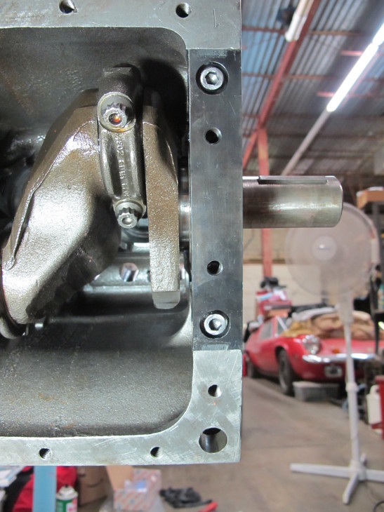
The next step was to install the front sealing block. It's the dark piece just above the crank here.
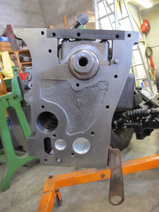
Originally, Triumph used wooden wedges to seal up the ends of this block. The gasket kit I bought supplies neoprene blocks to replace the wood. The problem is these are 50% thicker than the slot they are supposed to fit in.
The block couldn't be dry fit with just one of these in place. They can't be driven in, especially once sealant is involved. What I ended up doing on Sunday was coating all of the contacting surfaces with silicone sealant and letting the extra fill the slots, then trimmed the extra. I'm not very confidant this would survive many heat cycles due to expansion. I may try trimming the thickness of the neoprene a bit and use non-hardening Hylomar to seal up the block ends.
I also started cleaning the block a little at a time. The crank area is very clean, but there's still some debris probably left over from the cam bearing install around the tappet holes. The tappet holes are mostly clean, but some of the bores may have light rusting that could use a few turns from a cylinder hone. I may as well address this while the block is upside down.
JoeTR6
HalfDork
8/13/16 6:44 p.m.
It was a sweaty day down at the shop today. I managed to reinstall the front sealing block on the engine after trimming down the neoprene wedges used to seal the ends. Hopefully there will be no leaks, at least not beyond the usual weeping.
With that done and the oil pump lubed and installed, it was time to start on the cam. Before committing to lubing the cam, I made sure the block was clear of debris and did a final check of the tappet area. It's looking pretty good. So I cleaned and bolted up the front cover plate (with a quality gasket and Hylomar). The cam was lubed and installed. The end float is at the lower tolerance of 0.004". Test fitting the timing set showed that the crank sprocket needs 0.010" of shims to align with the cam sprocket. This engine didn't have any, so I'll either find some tonight in my spares or cut some tomorrow.
JoeTR6
HalfDork
8/14/16 4:45 p.m.
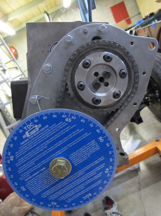
The cam is now timed. The big question is what cam do I have?
I made a shim for the crank sprocket and it now lines up with the cam sprocket. Then I installed a timing wheel and set TDC using a piston stop. After that, it was fairly simple to time the cam except for the excessive sweating. I'll blame the heat for me at first timing the cam to Richard Good's GP2 cam specs. Once I found the intake opening angle for a late stock cam, things went smoother. One weird thing is that the cam I have appears to have a duration of 248 degrees, but it's supposed to be 256. Even the earlier stock cam duration of 240 doesn't match. Maybe the profile changed when it was reground, but 8 degrees is a significant change and reduction in potential power. I forgot to check the lift, but everything is still set up on the block so that I can easily do it this week.
JoeTR6
HalfDork
8/14/16 5:06 p.m.
I just realized my error. The only specs I have for the stock cam are the valve opens at 18 BTDC and closes at 58 ABDC. I was measuring valve opening at a 0.010" tappet lift, but forgot that the rocker ratio is 1.45, so 0.010" of valve lift (the valve lash) equates to 0.007" of tappet lift. So I'll need to adjust the cam a bit.
Assuming the cam profile is symmetric, the peak intake lift should be at 110 ATDC. This may be a more accurate way of timing the cam (or at least checking it).
JoeTR6
HalfDork
8/15/16 6:00 p.m.
This was bugging me all day, so I stopped by after work to adjust the cam timing. I retarded the timing one cam tooth and adjusted the cam sprocket so that peak lift occurs at 110 ATDC. This was done by finding the crank angle at 0.050" below peak lift to both sides and determining the center angle. The adjustable cam sprocket gives me +-9 degrees of adjustment, but it's set now to allow more advance than retard from the stock timing.
I'm going to modify a timing chain cover to somehow allow access to the adjustable timing gear.
JoeTR6
HalfDork
8/17/16 9:03 p.m.
Well, I thought the cam was done. Tonight I checked the opening/closing angles and found that they are shifted 4 degrees from the measured highest lift point. That's no big deal as the timing can be adjusted with the cam gear. The bad thing is that the measured cam lobe lift is only 0.212". According to the Internet and my unground but worn stock 1973 cam, the lift should be 0.240". The cam I was going to use came from my restored TR6, and that engine was rebuilt over 20 years ago. I'm fairly certain the cam was reground, but am surprised they had to take off that much. Accumulated wear could be a factor, as I estimate this cam has run over 70k miles total.
My worn '73 cam has a lovely pit on one on the lobes, so it would need reconditioning. Alternately, I could just say screw the rules and get a new GP2 cam from Richard Good. That would make the car much more fun to drive. Hmmm...
Dusterbd13 wrote:
Cam it. Screw the rules.
Agreed. You're doing such nice work on this car to put an inadequate cam into the heart of things.
JoeTR6
HalfDork
8/18/16 11:08 a.m.
I think you guys are right. The stock cam falls on its face at 4500 RPM. You lose a little low-end torque with a bigger cam, but the power above 4500 is actually usable. The lift of the GP2 cam isn't that much more (0.258 vs. 0.24), but the longer duration makes it much more flexible.
FWIW, I found that the Roadster Factory sells Richard Good's new cams with a stock profile. So I certainly won't bother with having a worn-out cam reground (again).
JoeTR6
HalfDork
8/18/16 5:25 p.m.
Sigh. I pulled the cam to get the part # directly from it. It's an early ('69 to '73) cam. This sparked a 25 year old memory that the machine shop found a pit in my late cam from a '74, so I settled for the original '73 cam in my restored TR6 (which is actually a combination of the two cars). So I got the cams reversed. Next time I'll check the numbers first. It must be my subconscious trying to prevent me from cheating, because that is the proper cam for the engine I'm building. If I go to Nationals with this car, I'll put the right cam back in. 
What's weird is that the 1972 engine that I'm rebuilding now had a late cam in it. That's a cheap way to get more lift and duration, so isn't an uncommon mod.
JoeTR6
HalfDork
8/20/16 9:18 p.m.
To make it easier to experiment with cam timing, I modified the timing chain cover to allow access to the adjustable cam gear.
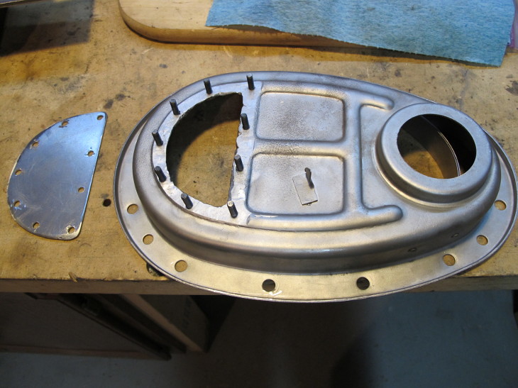
This was one of those relatively simple mods that took some time. Simply welding nuts onto the inside of the timing cover may have interfered with the timing chain. I decided to weld some button hex screws to the inside to act as studs. This has the advantage of not pushing crap into the cover while running bolts in. The flange left after cutting the hole was fairly level but rounded. So I welded the inner lip of the flange and ground it mostly flat, then chucked the cover onto a Bridgeport mill to cut a nice level surface. That left the flange a little thin, but I simply welded a bead around the perimeter on the inside while welding in the button screws. It's precise enough that a paper gasket and some Hylomar should seal it up. The studs are a bit long, but that's all I could find on a Saturday. I may cut them down 1/8".
I test fit the cover and checked TDC with the new crank damper. Dead on. I still need to mount the timing wheel and sensor, and will probably weld a mount directly onto this cover. Spanning across the cover like I've done before would block the access hole I just made.
The mess you can't see above in that picture is the rocker assembly being rebuilt. The rocker shaft is heavily grooved and not really usable if I want smooth valve action. There's another $150 for a proper part.


