1 ... 8 9 10 11 12 13
Mezzanine
Mezzanine Dork
5/31/18 4:15 p.m.

I opened up the trunk to find a good place to install the wideband O2 sensor controller.

Let's see what's under this false floor and insulation pad.

This foam stuff is not appropriate for this task at all. The false floor is solid thanks to some kitty hair and POR15 from the previous owner. I suppose I can thank them for getting rid of the moisture holding insulation Fiat put in here from the factory, but I'll need to replace this stuff.

A close inspection of mounting locations for the wideband controller led to a change of plans. Turns out the sensor leads are long enough to run all the way from the wiring bay back to the header. That's good news because I would have been stuck de-pinning connectors if I mounted it in the trunk and ever had to replace it.

The wideband sensor leads are visible in the bottom of this next photo, laying over the top of the transmission along with the speedometer cable.

Also in the above photo: a complete engine harness. The only un-terminated wires you see there are the air-idle control wires I decided to add just in case I found the need to use one. It won't be part of the original configuration, but it's good to have in case it proves necessary.

Mezzanine
Mezzanine Dork
5/31/18 4:33 p.m.

I woke up this morning and realized it's time to get the engine back out of the car since I don't need it for locating wires any more. But first, I need to check some clearances:

First, crank position trigger wheels. I threw the control arm back in to make sure it cleared. Lots of space.

Second, where will the fuel pump go? There's plenty of room down in front of the transmission. See the red box in the pic below for approximate location.

The big yellow bracket directly above the red box is where the fuel filter will get mounted.

Then this happened again:

Notes about engine removal: way easier without the header on it. Also, DEFINITELY take the fuel injectors and rail off so you don't have to worry about damaging them while lifting the car off the engine.

Now to get the firewall penetration figured out. The factory seal will need pretty extensive modification to seal up the new stuff. Specifically one huge wire bundle and two smaller bundles. I also organized the factory stuff and will be looming it up a good deal cleaner than current.

Here's what I have to work with:

Then I made a new punch list. It's long. frown No particular order:


Mezzanine
Mezzanine Dork
6/4/18 9:50 a.m.

Let's whittle down that to-do list.

I needed to clearance the left frame rail (so to speak, since it's unibody) to clear the five speed. I could have made the room I needed with a hammer, but I decided to do a nicer job. Sharpie marks made while the engine was installed:

Death wheel does its thing:

Took a peek inside the rails to see how it looks. Brown factory primer everywhere and solid metal. yesheart

Template (CAD joke goes here):

Rough fit:

Primed the whole thing inside and then welded it up.

I hosed a bunch of primer into the frame rail through some existing holes. Left all the metal work a little coarse because this is pretty much invisible once the engine is in.

While the welder was out it made sense to get the fuel pump mount sorted. First I put the fuel tank back in:

Then I made a bracket for one ear of the pump mount. The other is attached to the body of the car itself.

That'll work. Just clears the forward control arm bolt - the pump discharge fittings shown aren't what I'll actually be using. The new stuff will provide more clearance than shown here.


Mezzanine
Mezzanine Dork
6/4/18 12:13 p.m.

Needed to get the MAP sensor mounted. So I made some simple mounts to add it to the Coil bracket. Coils are electrically noisy, but I don't know if the MAP sensor will mind.

Mounted in place:

Have I mentioned how cool Rivnuts are? I'm using them pretty much everywhere lately. Moving on, I spent a good deal of time cleaning up the factory wire runs that remain. There's just two going to the engine: coolant temp and oil pressure idiot light. Other than that there is just the starter +12V and starter solenoid wires. This is starting to look a lot better:

Remember when I first pulled the motor and found that the subframe was welded to the car in the back? That's because one of the captive nuts was totally stripped. While I had the welder out I planned to cut/weld a new one in, but found the diameter was close enough to tap out to 10mm. The threads feel a little soft, but I torqued a bolt up to 35 lb-ft which is about what I'd put on the 8mm that is supposed to be there, so I'm calling that good enough. If it proves to be a problem down the road I can easily address it with the engine in the car.

Last thing I worked on this weekend: vacuum ports for the intake. There was no vacuum provision on my manifold or Jenvey throttle bodies, but there was a spot on the bodies where they *should* go. So I drilled:

3/16" for the brass tube I found at the local hardware store. I only drilled most of the way through the body in this size - the last bit penetrating the intake port I did with 1/16".

Cut the tube then flared each piece. I shaped the flares with a little hammer work to roll the edge. I then added a little locktite to the tubes and pressed them into place. Nice tight fit.

The checklist is getting shorter rapidly. I'm basically doing everything I can to put off painting the engine bay because I'm not looking forward to masking everything. But I'm super excited to be making so much headway. My informal goal of getting it running before Hungary Bill visits at the end of the month is looking more and more realistic. Too bad I have to travel for work again next week and the week after.


Hungary Bill
Hungary Bill GRM+ Memberand PowerDork
6/4/18 1:01 p.m.

gumby
gumby GRM+ Memberand Reader
6/4/18 6:23 p.m.

Sweating those details! Coming together well.

FunkyCricket
FunkyCricket New Reader
6/7/18 1:05 p.m.

As an IT guy, yes, I have velcro, zip ties are the devil's children. They eat wires. Glad to see you weren't using any!

Second: wow, thank you for sharing. There are so many inspirational people on this site saving cars and doing cool things. 

Stefan
Stefan GRM+ Memberand MegaDork
6/7/18 1:15 p.m.

Seriously, seriously great work.  I'm completely jealous and I'm loving the updates.  Keep them coming!

RossD
RossD MegaDork
6/7/18 1:30 p.m.

Is the undersized hole for the vacuum port typical? I guess I've never really paid attention enough or even had enough exposure to vacuum signals.

edizzle89
edizzle89 Dork
6/7/18 1:53 p.m.
RossD said:

Is the undersized hole for the vacuum port typical? I guess I've never really paid attention enough or even had enough exposure to vacuum signals.

i'd guess since he wont have a plenum the small holes will help dampen the vacuum pulses of the individual cylinder. or i could be totally wrong

badwaytolive
badwaytolive Reader
6/7/18 2:02 p.m.

Great stuff here!

The timing is not great, but I'm about to embark on a wiring harness too. I found this guide from a race shop:

WIRING HARNESS MANIFESTO

It's pretty hardcore, but the information is cool to know.

What sensors are you using for the crank trigger and cam trigger?

damen

Mezzanine
Mezzanine Dork
6/7/18 3:53 p.m.

No more procrastinating. Engine bay cleanup time. Before photos:


See those giant metal brackets used to hold the factory coolant reservoir? Time for a bracket-ectomy.

Bye Felicia.

Masked and scuffed. Note all the POR15 applied by a previous owner: some stayed, some scuffed right off with a scotch brite pad on the die grinder. I decided to prime over it...hopefully I don't regret that decision down the road.

Shoutout to the person here on GRM that used foil for masking parts - I'd never seen that before and it's a spectacular idea.


Dusterbd13
Dusterbd13 MegaDork
6/7/18 3:58 p.m.

Por15 only sticks to metal that is properly rusted. Not light surface rust, shiny metal, or paint.

I learned the foil masking trick from muscle car review back in the day on an engine bay detailing article. I know ive shelared it here at least once, but im probably not the guy to thank

Mezzanine
Mezzanine Dork
6/7/18 4:02 p.m.

Paint selfie from last night for all the lovers out there:

Notice the trigger control. Primer was shot with a cheap Eastwood gun that they've since discontinued since it's kinda crap. Basically a tiny bit better than a HF gun.

Shot primer fine with the 2.0 nozzle. I'm sooooo thrilled to see at least ONE part of the car a solid color!

This morning I scuffed the primer before getting my daughter off to school. Then at lunch this happened:

Paint laid down really nicely. I lost count how many coats - I mixed up about 20oz of paint and just kept adding coats until it ran out. Ten?  It's PPG acrylic enamel single stage. Not what I'll use on the rest of the car, but it made sense for the engine bay.

Mezzanine
Mezzanine Dork
6/7/18 4:19 p.m.

In reply to badwaytolive :

I read that thread thoroughly before doing my wiring too. Definitely overkill for our needs, but the education doesn't hurt. So much solid information there.

The trigger and sync sensors are both a Honeywell part. I chose them for two reasons: compact size and connector interface. Most aftermarket hall effect sensors have a pigtail, and I didn't want that. P/N: SNDH-H3C-G03. Available from Mouser for just $26 each. Honeywell sensor from Mouser.


Regarding the vacuum signal, I have no idea - I don't need a large vacuum source to drive a brake booster, and yeah, I was hoping a smaller port would minimize scavenging from neighboring cylinders. I will be feeding a small vacuum log with a tube from each runner. I only need the vacuum signal for fuel pressure regulator reference and for MAP. Note that MAP signal is only to be used at throttle inputs <30%. Everything above 30% is basically atmospheric and the MAP signal is useless.


Duster, since you raised your hand for the foil wrapping, you get my thanks. laughyes And I'm hoping the POR15 will behave since it's going to just hang out in the engine bay. I stabbed at a lot of it with a scraper before scuffing and sanding, so what's on there feels pretty solid. Fingers crossed. indecision

FunkyCricket, Stefan, et al, thanks so much for the kind words and motivation!  23 days until Hungary Bill is in town for a visit. 23 days to get this thing running. laugh

Mezzanine
Mezzanine Dork
6/11/18 11:24 p.m.

Continued to chew through the punch list this weekend. After getting the engine bay painted, it was time for some more mechanical tasks. First on the list was getting the firewall sealed back up.

The factory firewall seal was a rubber-coated metal seal plate that didn’t actually conform to the two small bundles of wire or the throttle cable passing through. It made a half-hearted effort to make the gaps smaller, but no actual sealing efforts. I added two large cables and one really big wire bundle, so I would need to mod the original seal. I used some inner-tube from a bike – two pieces with holes cut between them in the right places. I then used tire patching compound (rubber cement) to glue the two inner tubes together around the wire bundles, cables, and throttle cable. I was pleasantly surprised how well the rubber cement worked on the material.

Then I cut up the factory seal to make the requisite room and then screwed it to the firewall.


It still doesn’t seal completely, but I didn’t really expect it to. It’s performing some chafing protection and should minimize air from the engine bay traveling into the passenger compartment.

Next up is a task I’ve put off for a while. Setting up the crank position sensor and trigger wheel. I put it off because it’s a job with a high criticality. Gotta get this one right. Too much runout in the trigger concentricity and either the sensor won’t read or you’ll wind up with trigger errors. First, modify the factory crank sheave. I needed to cut a shoulder into it. It performs two functions: centers the trigger wheel, and makes a flat surface to mount it to. Set it up in the lathe with the four jaw chuck and got it to .005mm runout.

Next I had to cut the center out of my ill-suited trigger wheel. I’d hoped to find a trigger wheel that fit my application better, but failed in finding something in the 5”-6” range. So I just used this 7” wheel I already had lying around. Down side was that to get it chucked up I could either make a mandrel that would allow me to hold the wheel from the center or I could use the chuck jaws on the outside of the wheel. Outside works fine, except you have to move the dial indicator to clear each chuck jaw. This made getting it centered on the lathe pretty tedious.

In hindsight I would have been better off making a mandrel. Either way I got it done. Center cut out and pressed onto my crank sheave:

Still not done – I need to drill and tap 3-4 places to secure the trigger to the sheave, but I won’t do that until I’m totally confident in the placement. I better get my the alternator alignment right - the trigger wheel is a giant spinning wheel of death for any v-belts that stray far:

While I was working on the crank sheave, I also swapped the timing belt sprocket over to a later 1500 style – it has a belt guide flange on the inboard side. A job the 1300 left to the cam sprocket. Since I’m using an aftermarket veneer cam sprocket without a guide flange, I need to make the switch to the later style. Notice how much thinner it is?

T-minus 19 days.


Mezzanine
Mezzanine Dork
6/12/18 11:11 p.m.

Next up: truing up my intake manifold. The sealing face on my Pierce intake manifold was as flat as my straight edge, but since the intake shares two bolts with the exhaust manifold I needed to make sure they’re exactly the same thickness. I already knew they were way off, so Atlas Shaper to the rescue. I chucked the manifold into the shaper and removed some material from the bolt bearing surface. Chucked up:

Surface finish from the shaper is always so nice.

Mounting the crank position sensor would be tricky since there isn’t a lot of fasteners in the neighborhood to re-purpose or piggyback. I decided to borrow one of the M6 bolts used to hold the timing belt cover on. I needed to make it the same height off the block as the other mounting boss I’d be stealing. Cut a SS bushing out and epoxied it into the housing, visible in the background here alongside some card stock first drafts for the sensor mount.

First iteration half done here in steel. This is the bottom half of the mount. Take special note of how nicely the trigger wheel fits with the cam belt cover on – it’s like it’s made to be on there. Plenty of room.

Final iteration seen here waiting for the paint to dry. I’ll get another shot when I get home from my business travels this week.

Other tasks from this weekend:

  • Filled transmission with Redline MTL
  • Fuel system layout work started, but no hoses cut. Had to order some more fittings. This work will be easy enough when the engine is in the car
  • Mounted fuel filter and pressure regulator
  • Replaced the heater hose that runs down the center tunnel of the car in the interior. It’s kind of a pain to get to when the interior is in place.
  • Started doing some head scratching and noodling over the throttle linkage. I want it to be progressive: high resolution at low throttle openings, but little pedal travel between 40% and 100% throttle. I’d love suggestions on how to approach this.
NOHOME
NOHOME UltimaDork
6/13/18 6:46 a.m.

In reply to Mezzanine :

Who just has a shaper lying around the shop? That is a a pretty arcane piece of hardware for a home mechanic.


Pete

Mezzanine
Mezzanine Dork
6/13/18 9:56 a.m.

In reply to NOHOME :

It's a fine machine, and faaarrrrrr cheaper than a mill. My entire shop could be described as a "war era machine shop" if you exclude the welders.

I don't use the shaper that often, but it is still pretty useful. The lathe I use all the time though.

Mezzanine
Mezzanine Dork
6/20/18 11:42 a.m.

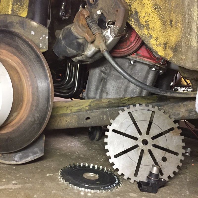
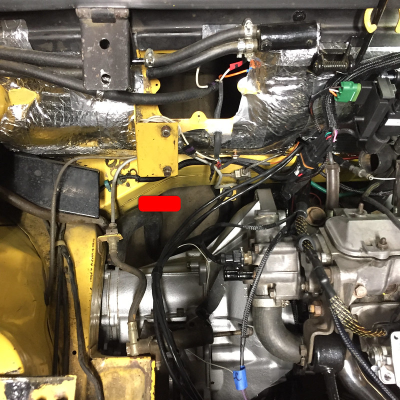
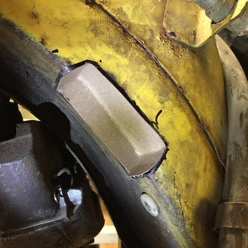
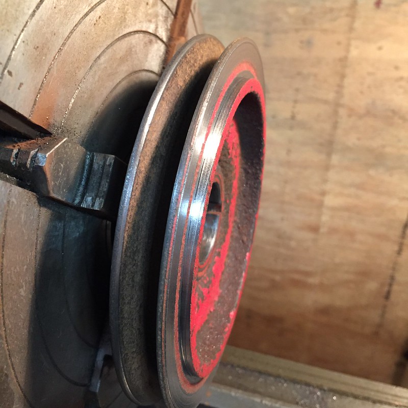
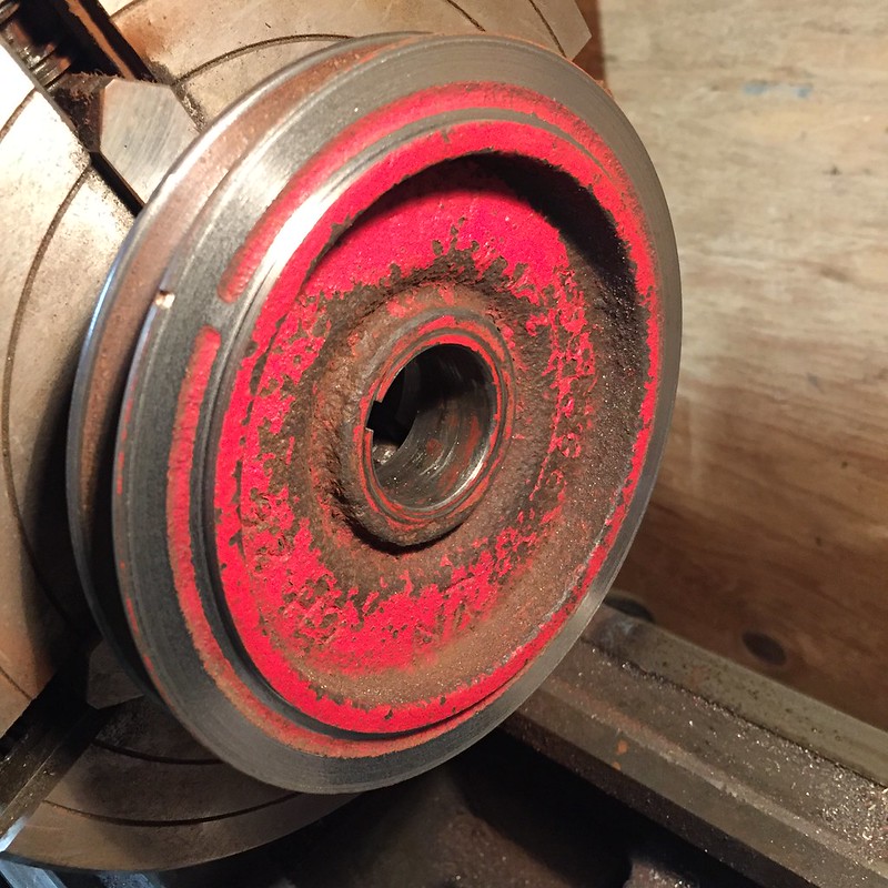
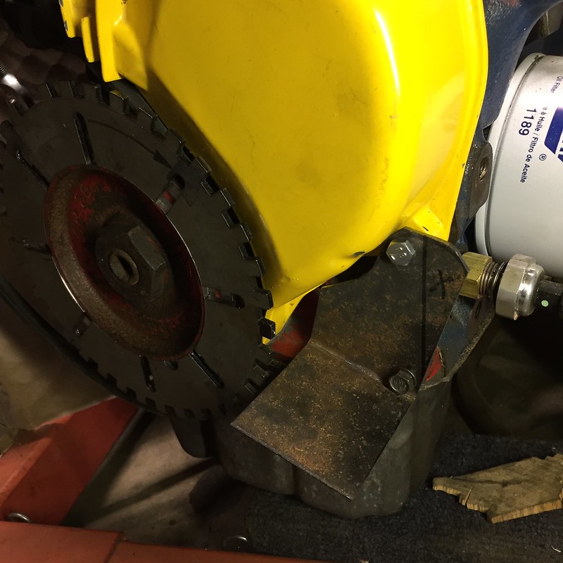
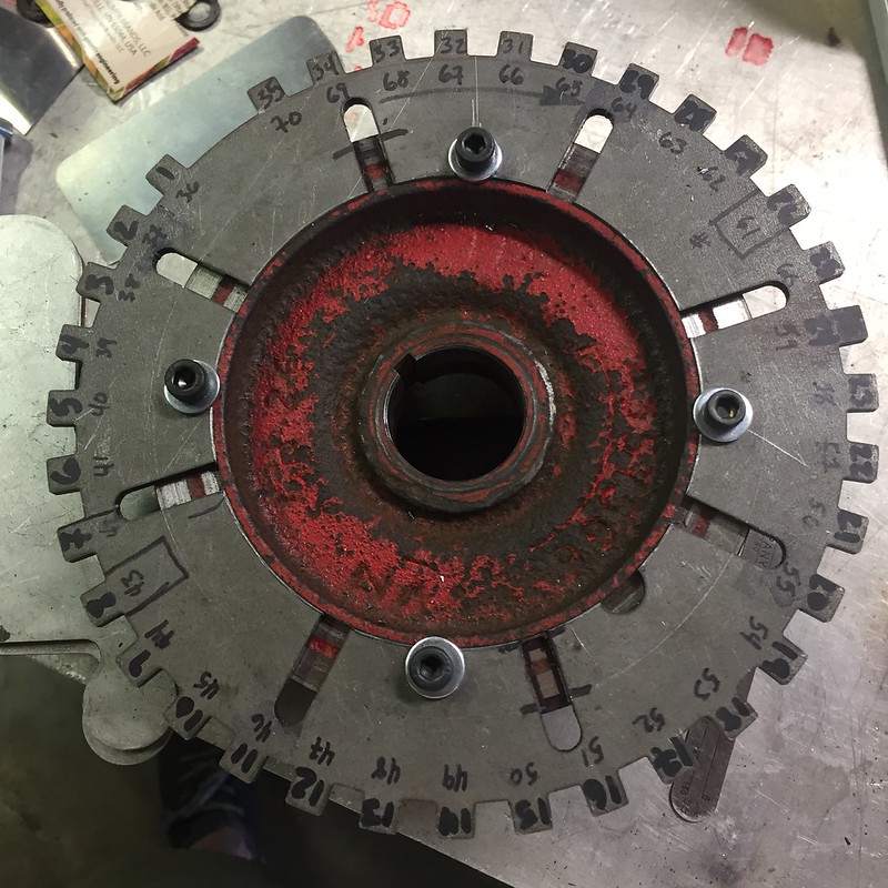
Lots of time invested noodling over the placement of my trigger wheel relative to TDC and the sensor. Like most 4 cylinders, this engine pairs cylinders 1 & 4 and 2 & 3 at TDC together, respectively. So all cylinders have TDC 180° from each other. I placed my missing tooth 90° from any TDC event, and set the sync tooth on the cam on the falling edge of tooth one (first tooth after the missing tooth).

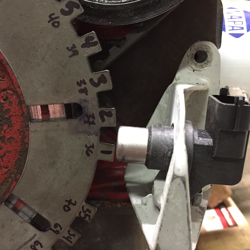
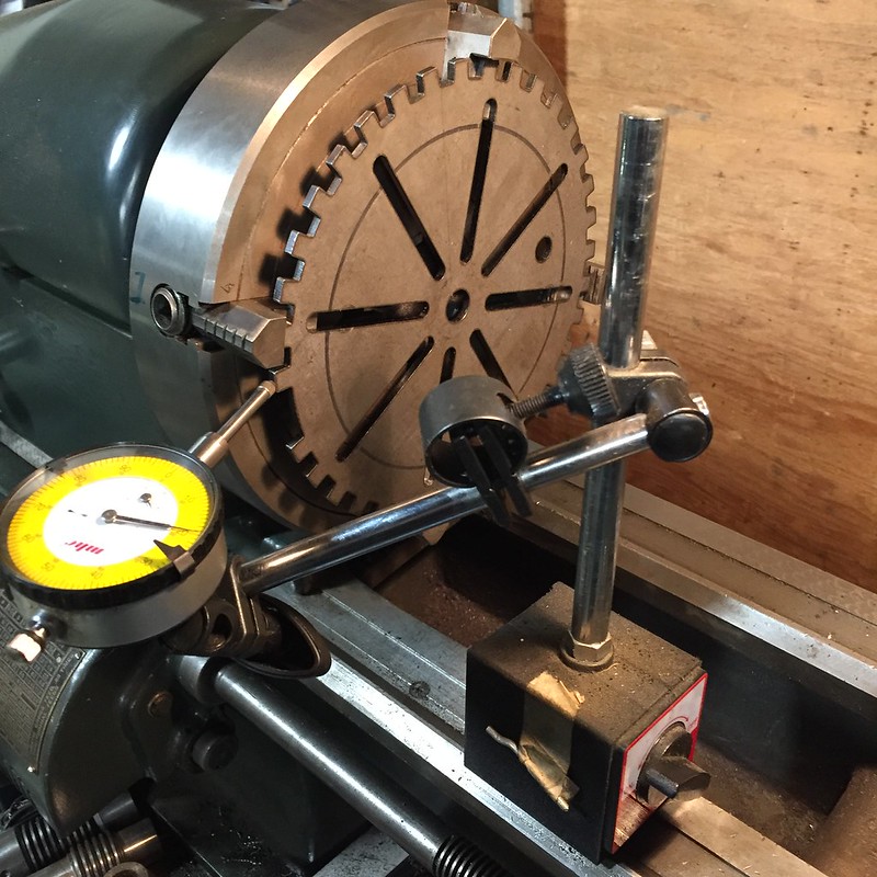
The firing order of the Lampredi is 1-3-4-2, but since my ECU will see cylinder 2 first after the missing tooth, my firing order gets changed to 2-1-3-4. Which is the same order, but it makes my head hurt a little not to have everything referenced from cylinder one. Remember the fun fact I mentioned back on page one or two about timing this engine? That's right: when the crank and cam are on their timing marks, you're ready to fire cylinder 4, not cylinder 1. Thanks Aurelio. None of this matters if you set the ECU up right. It just needs to know which tooth is TDC for which cylinder. Done with that task, I basically signed my death warrant and screwed the trigger wheel to the crank sheave. I'll slot the holes if I need to clock it a few degrees to get synced with the sync. The ECU has an oscilliscope built in, so that's one of the first things to test before actually adding fuel and spark and attempting to start the engine.

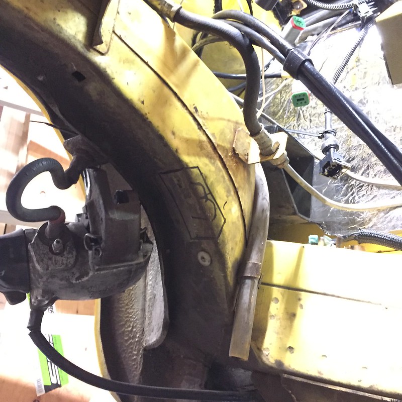
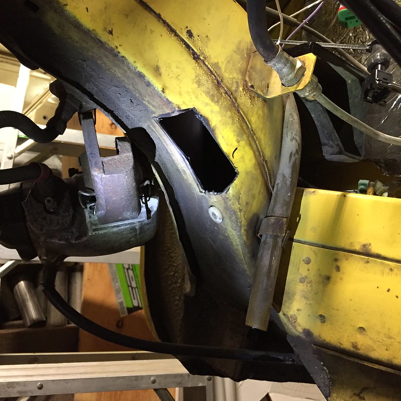
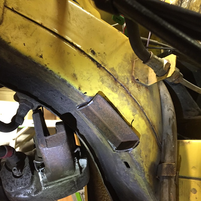
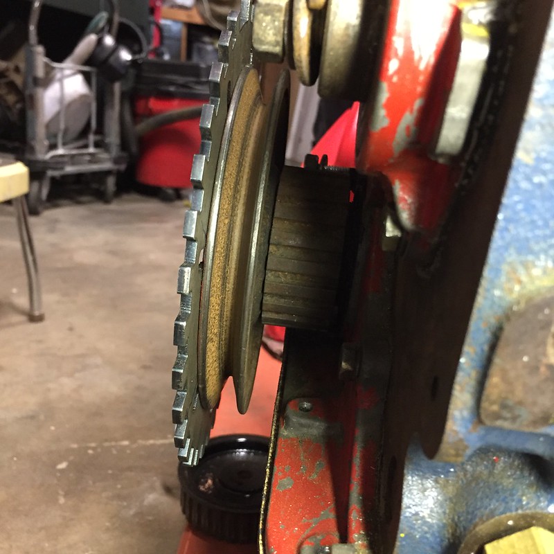
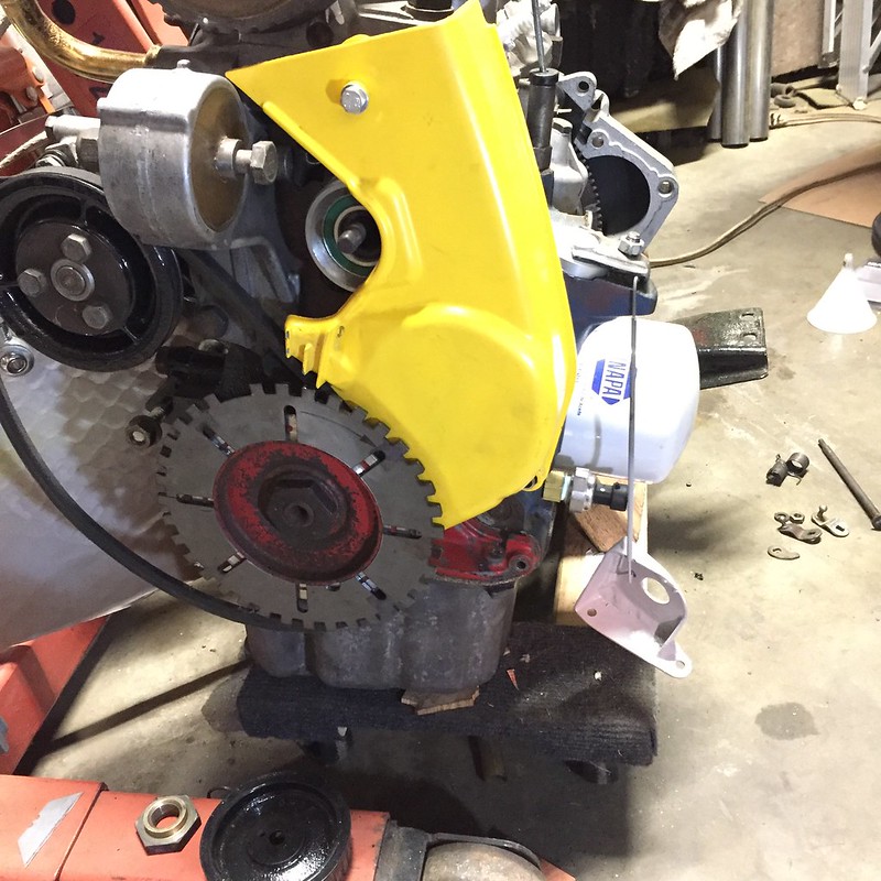
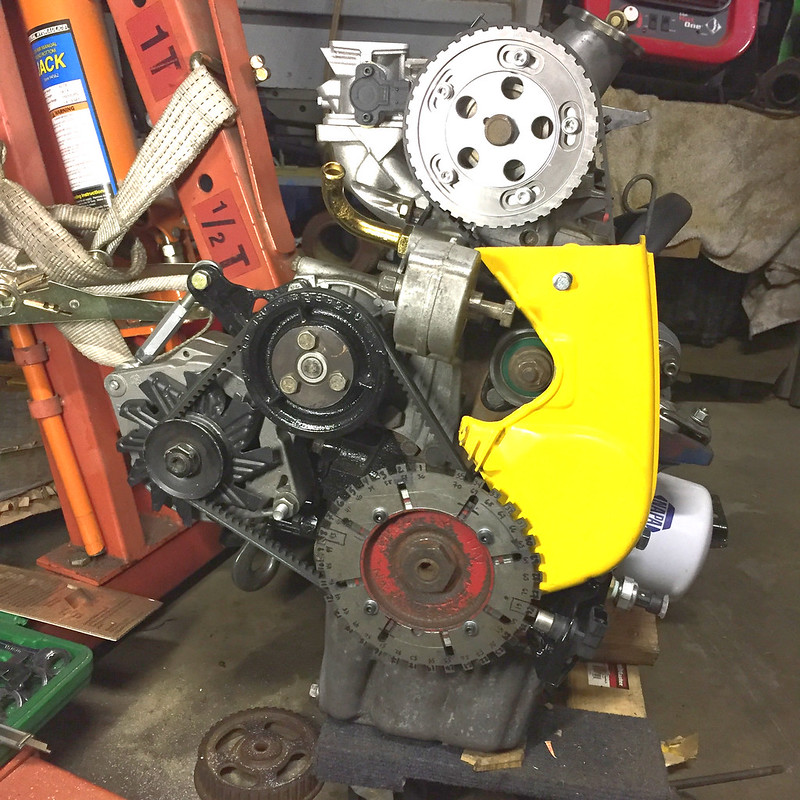
Getting everything timed and the sensors and triggers placed where they needed to be was SUPER tedious. I took the cam belt and cover and everything on and off at least a dozen times. It's aggravating that the timing belt cover is where the timing marks are, because you have to take it off to change the belt. You don't know if  you accidentally moved something until after you perform the very last step. On the 1500 engine they changed this, but since I stayed 1300, I get to enjoy this feature. The order of operations is very specific too. Oh, you haven't put the v-belt on yet? That's ok, you can removed the CPS bracket and timing belt cover to put it on now. indecision I think it's buttoned up for now:

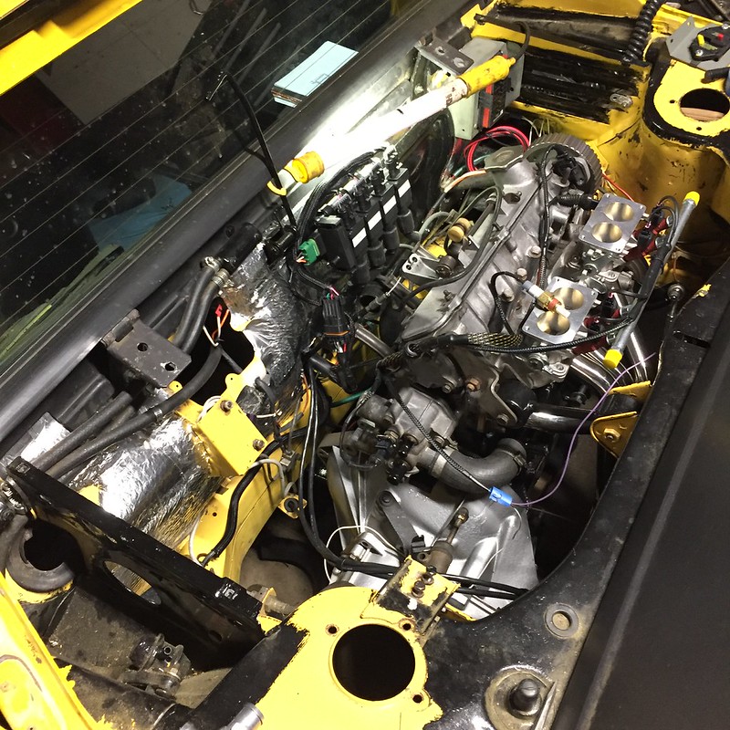
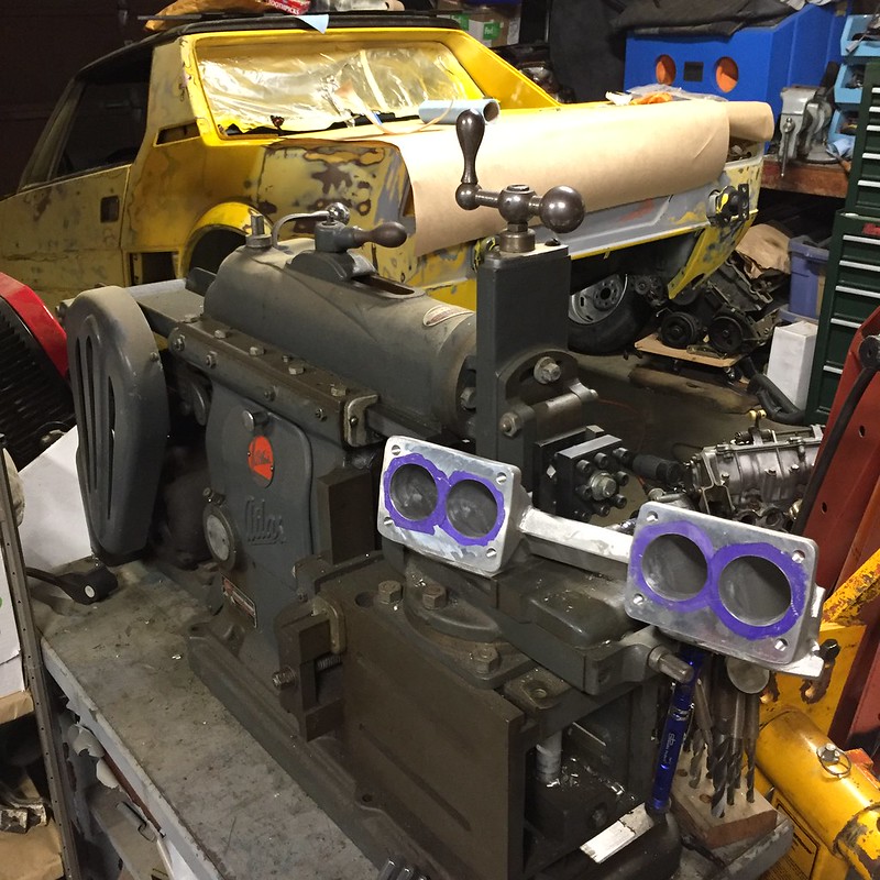
Did a little mock-up work on my throttle linkage. Think these zipties will hold? It only gives me about 60% throttle, so obviously a more permanent solution is planned. This might work for a first start though. Cable section is from a fuel injected 1500 throttle. I'm going to make a eccentric cam lobe on the idler arm (the part on the cam cover) to make it progressive.

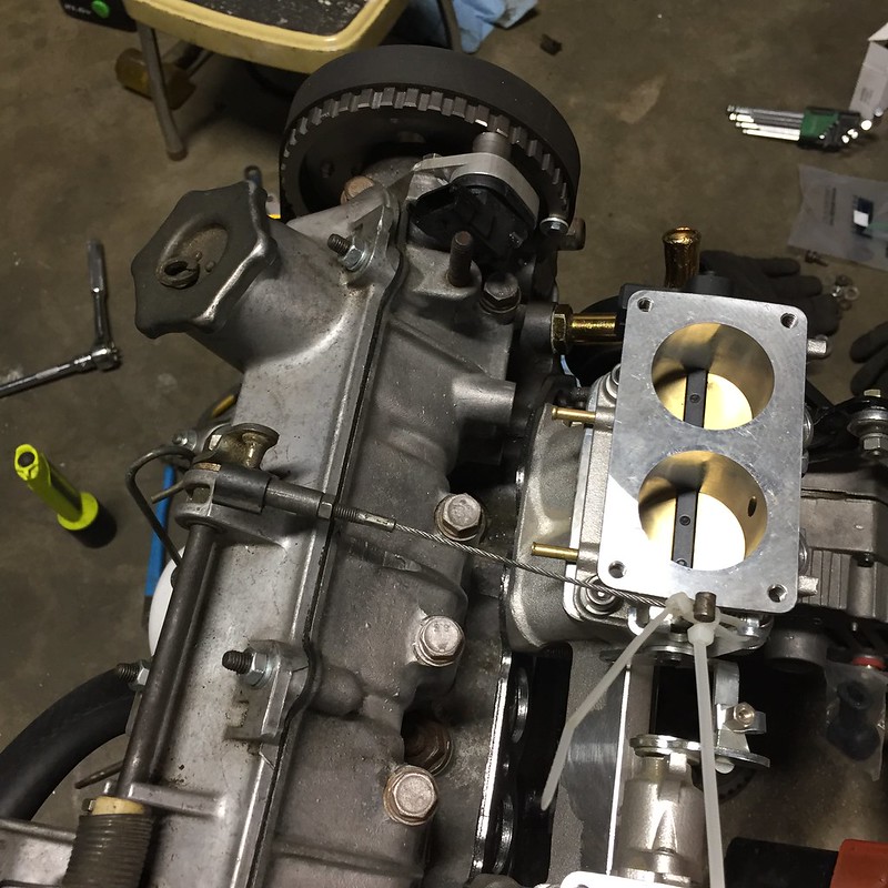
Honorable mention in the above photo - you can see the sync sensor tooth on the right side of the cam sprocket.

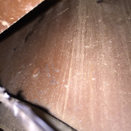
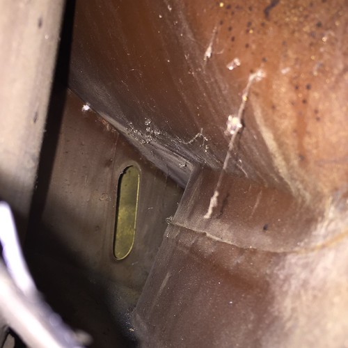
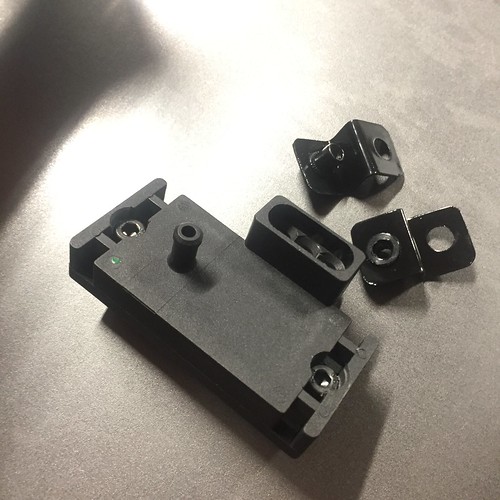
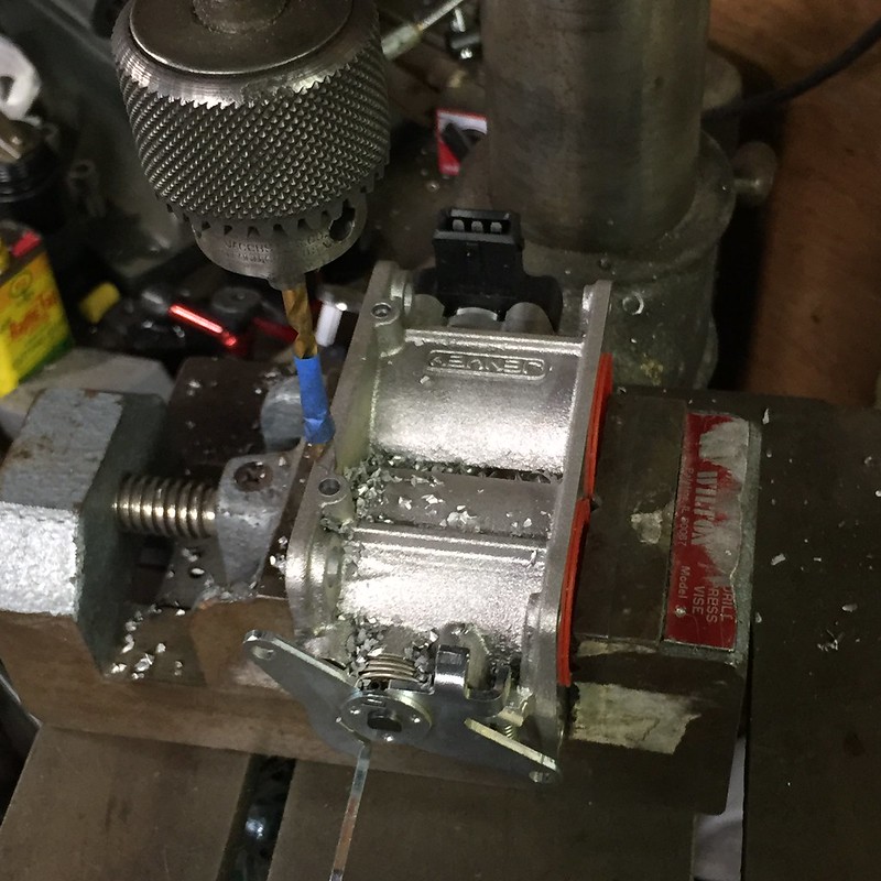
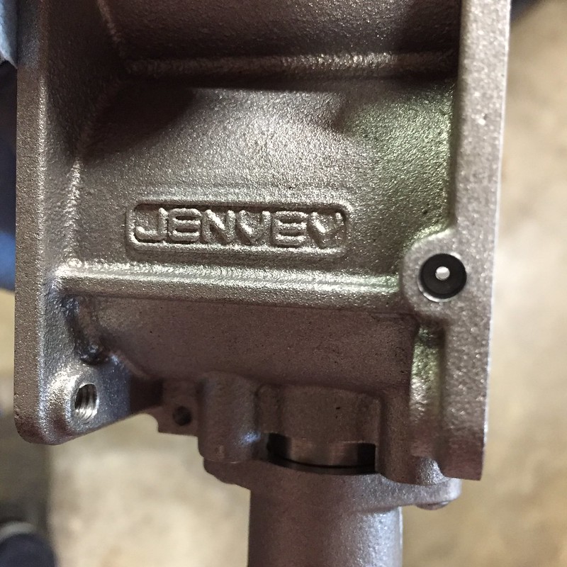
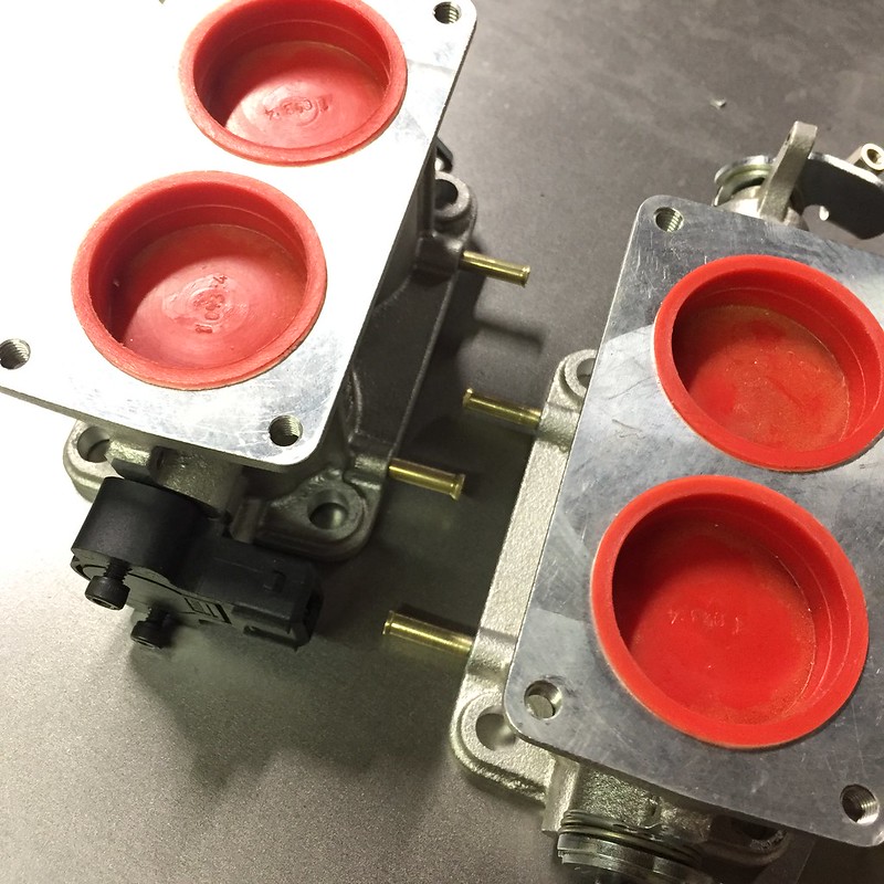
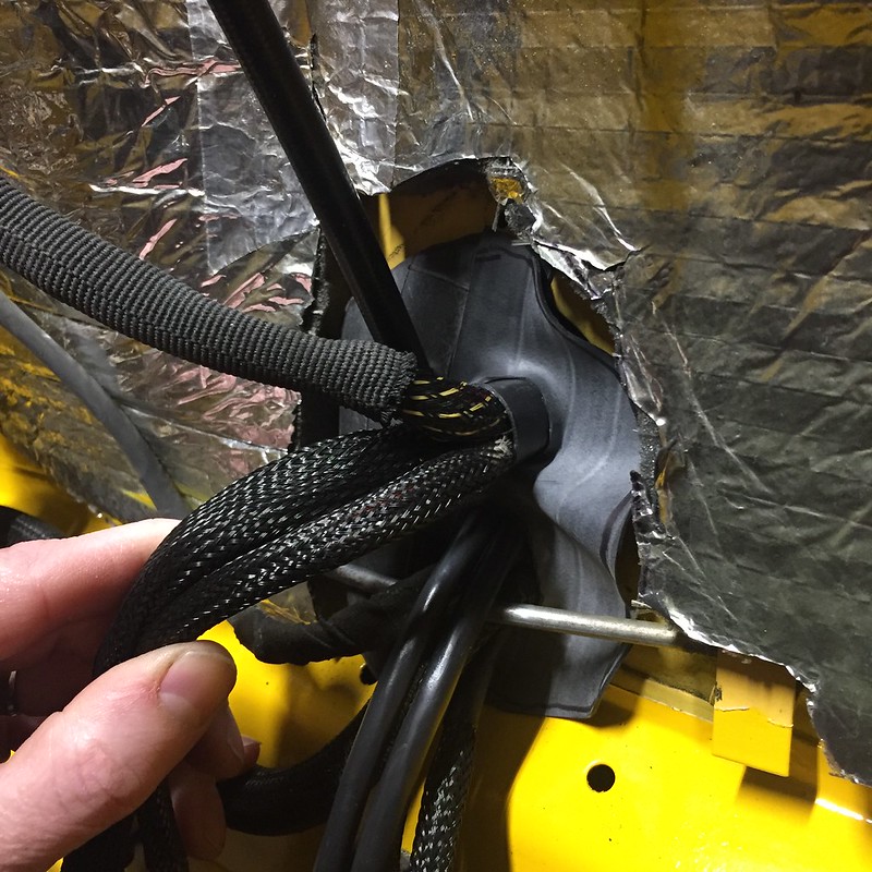
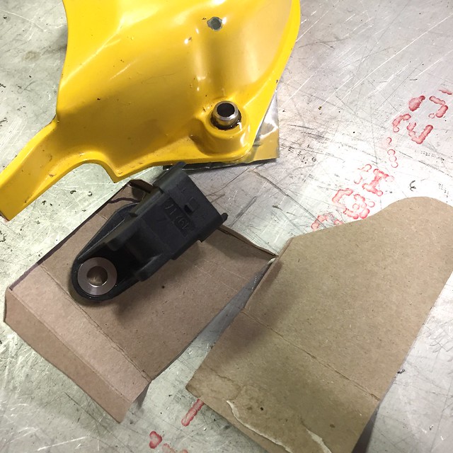
Speaking of throttles...finding the right o-ring for the Jenvey bodies has been giving me fits. This is the closest I've found so far:

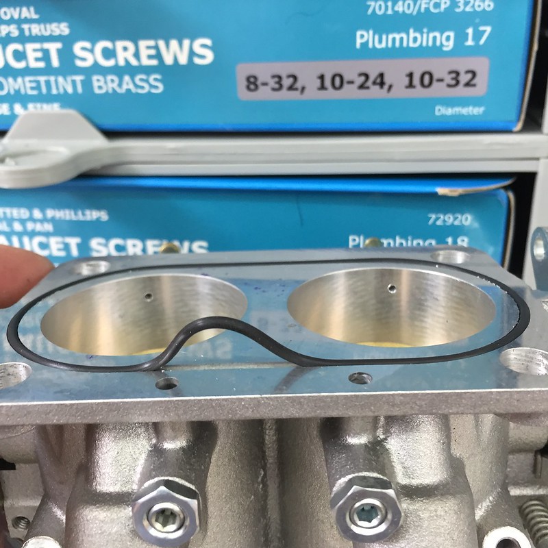
It's 1/16" thick, and about 3-3/16" diameter, or 81mm. I have two on order that might be close enough. If I fail there, I'll just cut some paper gasket material and be done.

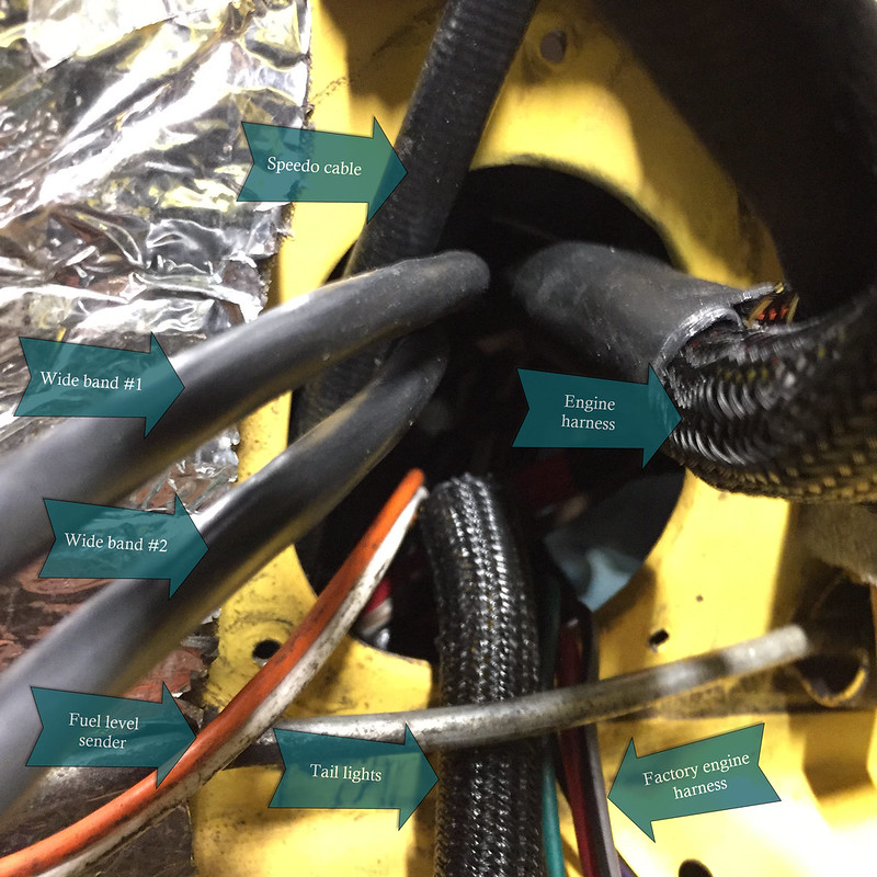
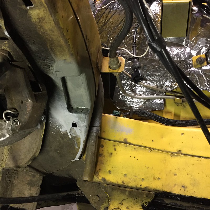
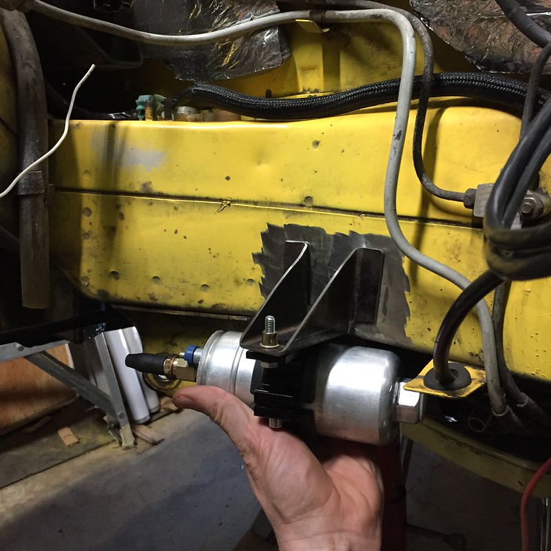
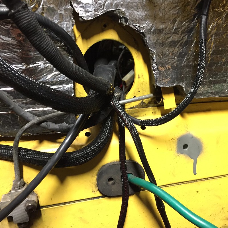
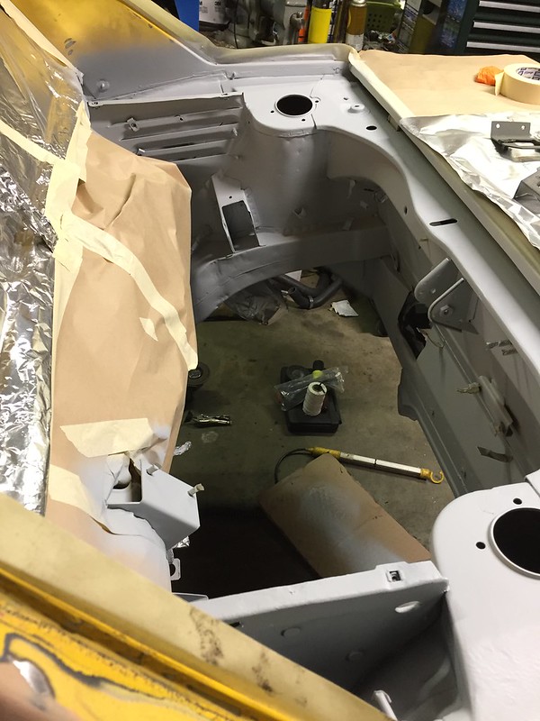
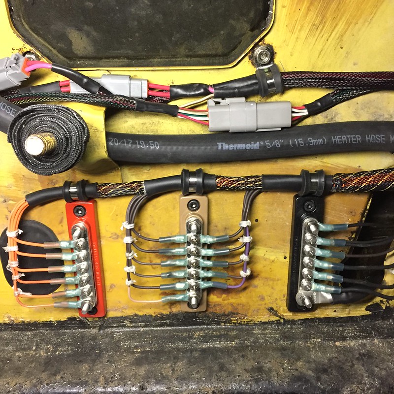
I finished up all my terminations. Fuel pump and reverse light switch are the only four terminations I have left to make, but I'll wait until everything is back in place before making those.

I wound up grounding the main ground bus on the right straight to the engine block instead of welding a ground stud to the body in the wiring bay. I'd been reading the Megamanual this weekend and remembered that specific piece of advice. No, I'm not using Megasquirt, but the Megamanual is so damn good, especially when you're mixing components from a gazillion different sources like I am. In the evenings this last week I got my base fuel and spark tables all filled in with some rough values that should be close enough to get the engine to run. I did math and VE calculations and stuff, which isn't particularly hard, but it does make you feel smart.

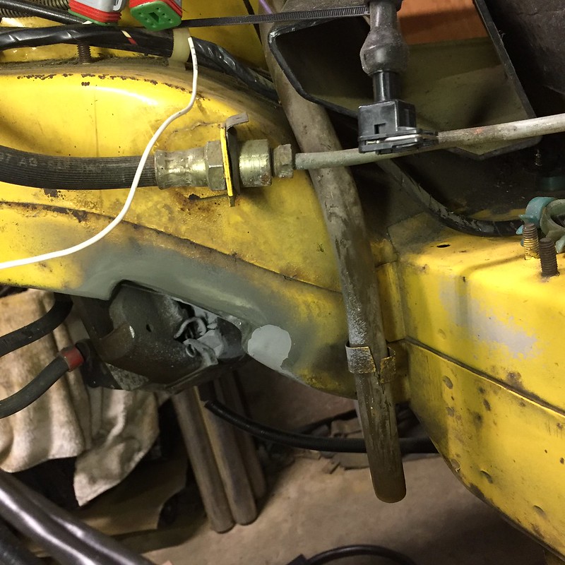
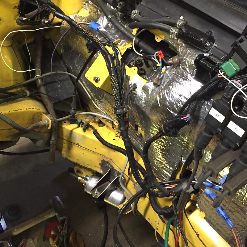
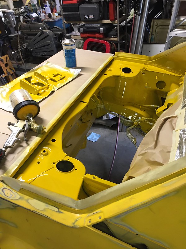
Final terminations made to my power distribution panel and main breaker. Fuel pressure regulator also visible here:

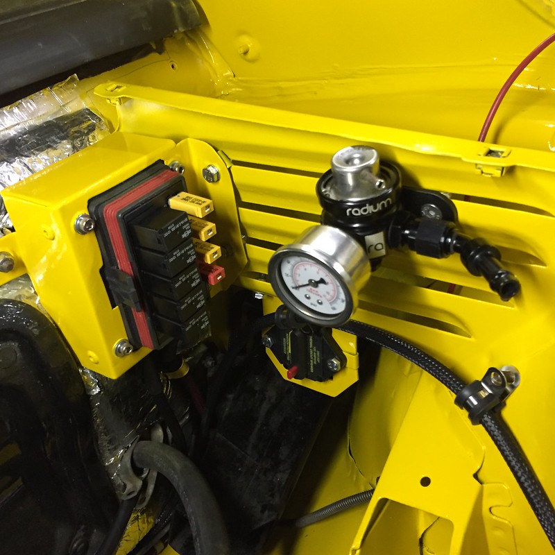
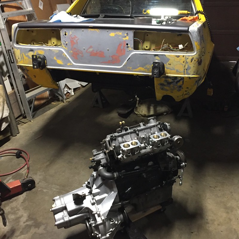
Ran all new wires to/from the alternator as well. There's a whole lot of braided loom happening in this engine bay now! I'm planning to slide the engine into the bay today or tomorrow as time allows.

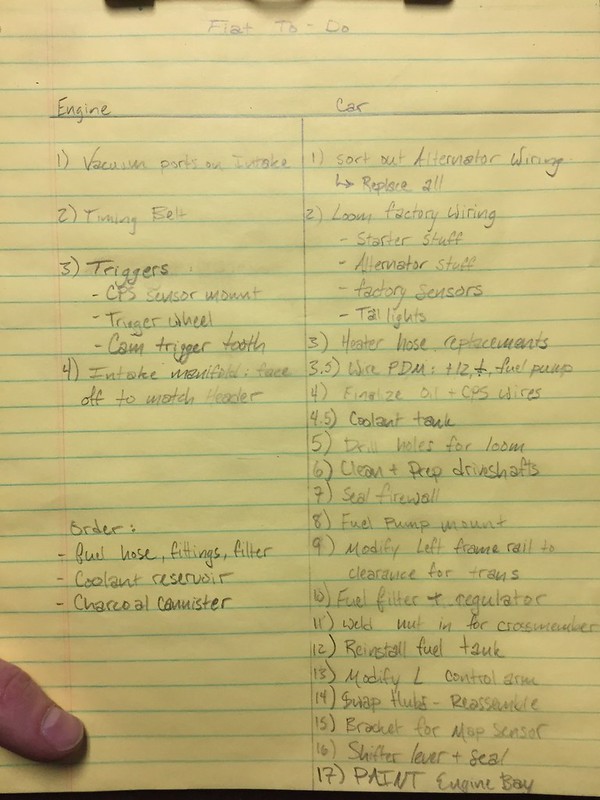
Ten days to complete the following tasks:

  • bolt engine mounts up, connect wiring
  • Fit fuel system - it's basically all here, I just need to cut hoses to length and crimp the hose clamps on.
  • Install battery
  • Verify wiring works as expected from power distribution module: ECU, injectors, coils, and fuel pump have power
  • Fill tank with fuel. Pressure test system.
  • Connect ECU and laptop. Update firmware on ECU.
  • Load base maps to ECU
  • Crank engine with fuel and spark disabled to verify firing order, trigger signals, etc. Adjust as needed.
  • Calibrate O2 sensor controler
  • Calibrate TPS
  • Enable fuel & spark, and attempt starting.

Bonus tasks:

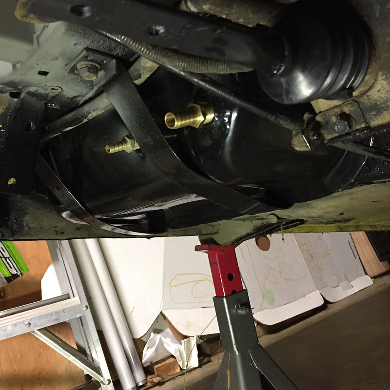
  • Modify driver's side control arm to clear transaxle housing
  • Swap in new 5-speed hub uprights
  • Clean and install new CVs. Build out drive shafts.
  • Reinstall suspension
  • Replace driver's rear caliper and install braided brake lines all four corners
  • Fabricate mount for coolant reservoir. Install
Ransom
Ransom GRM+ Memberand PowerDork
6/20/18 12:23 p.m.

Lovely work. That's some inspiring wiring.

barefootskater
barefootskater HalfDork
6/20/18 12:36 p.m.
Mezzanine said:

I see this picture and applaud the wiring. But the true genius that stands out to me is the use of whatever stud that is on the left as a velcro strap dispenser. Bravo. Party on.

wawazat
wawazat Reader
6/20/18 12:48 p.m.

Very nice wiring.  Inspirational even.  Are these three terminal strips/buss bars power, switched power, and ground?  Can you tell me where you bought them?


Mezzanine
Mezzanine Dork
6/20/18 4:05 p.m.

In reply to barefootskater :

Excellent eye, that stud is what the spare tire bolts to, and it is most definitely my velcro strap distribution/storage site.

In reply to wawazat:

The bus bars are a Blue Sea product, available here: Del City 100A mini bus with cover

I have the bus on the left distributing +5v to all the sensors, the center is a sensor ground to the ECU, and the one on the right is a common ground. I originally planned to do as you suggested and distribute switched power with a bus, but I didn't have enough consumers to make it worthwhile. As is I have a spare switched source relay in my power distribution module along with four extra circuits for future expansion.

Thanks for the kind words everyone!


Mezzanine
Mezzanine Dork
6/20/18 11:09 p.m.

In reply to wawazat :

I should note that I painted the bus bars myself to color code. They’re black out of the package. 

1 ... 8 9 10 11 12 13

You'll need to log in to post.

Our Preferred Partners
fRkUkXxHoQCuKpoYond1SGqrzC3MLInpYG3bbD7MM7MIAw5NHWFHg7yMowj8LHgF