1 2
burdickjp
burdickjp GRM+ Memberand New Reader
1/9/13 7:59 a.m.
Teh E36 M3 wrote: Wow. So I think I'm now understanding better your OCD mic'ing process: you're going at 120, 240, and 360 degrees rotationally, and from one end of the bearing surface to the other longitudinally to check for taper, correct? That's berkeleying thorough. Nicely done.

Not quite. I'm measuring three points on the crankshaft and each point a minimum of three times to ensure the measurement is accurate. If the three times I measure are more than 1μm from each other I keep measuring that point until I get three measurements which are within 1μm of each other. This method doesn't really follow scientific principles, as I'm throwing out data at my discretion, but it seems to do well for getting good bearing clearances.

burdickjp
burdickjp GRM+ Memberand New Reader
1/9/13 10:29 p.m.

I took some time and started into a blacktop head as well. This one isn't as far along. You can see it's not quite symmetric yet, but that's the beauty of doing this with plasticine first. As of right now I'm happier with how the blacktop port looks than the silvertop. It was easier to get this far with it. We'll see how it flows. I need to find a macro lense for these, or better lighting. Or both.

Jerry From LA
Jerry From LA Dork
1/11/13 11:06 a.m.
wvumtnbkr wrote:
Jerry From LA wrote:
burdickjp wrote: By my calculations, my main bearing clearances are as follows: 1 - 0.029 2 - 0.029 3 - 0.028 4 - 0.029 5 - 0.029 and my rod bearing clearances are 0.041 across the board.
Should be: 1-0.0029 2-0.0029 3-0.0028 4-0.0029 with a rod bearing clearance of 0.0041. Yes?
To clarify my statement(s): I thought that Jerry was commenting on the "count" of numbers (i.e. in his post he has 4 numbers whereas you have "5"). I was pointing out that there are in fact 5 main bearings, not 4. I later realized that Jerry was commenting on the tolerances and (in a round about way) the units. And, I concur that Mitutoyo kisk ass. end threadjack

I should've cut-and-pasted instead of transcribing the numbers because I did miss one. Had I done that, I would've matched up my numbers with burdickjp's. However, burdickjp did supply the answer I was looking for the question I was really asking.

The machinist will have quite a lot of fun with this motor.

pinchvalve
pinchvalve GRM+ Memberand UltimaDork
1/11/13 11:12 a.m.

I am in awe so far. Having "rebuilt" a 4AGE myself (I use quotes because compared to this, I slapped it together with a nod and a wink) I can't wait to see the end results.

burdickjp
burdickjp GRM+ Memberand New Reader
1/11/13 3:32 p.m.
Jerry From LA wrote: The machinist will have quite a lot of fun with this motor.

How so?

Teh E36 M3
Teh E36 M3 Dork
1/11/13 4:01 p.m.

Tolerances?

Jerry From LA
Jerry From LA Dork
1/12/13 12:30 a.m.
burdickjp wrote:
Jerry From LA wrote: The machinist will have quite a lot of fun with this motor.
How so?

I once asked a machinist to tighten up an extra half-thousandth on a main clearance. He told me flat out he couldn't guarantee it because the metal temperature comes into play as well as measuring error. This from a three-generation family in the same shop who ground their own cranks. They even offset ground my crank for zero deck (after milling the block) and a tad more stroke but tightening an already tight clearance within .0001 in. could not be guaranteed. Their cranks were things of beauty too.

burdickjp
burdickjp GRM+ Memberand New Reader
1/12/13 9:40 a.m.

The OD tolerance for Toyota crankpins is 39.985-40, so it's 0.015mm wide, which is 0.00059 in. Rather impressive for early '80's mass manufacturing.

petegossett
petegossett GRM+ Memberand UltraDork
1/13/13 2:32 p.m.

I just realized you're posting this on CICENET as well. Very cool build, I amazed by the level of detail you're putting into this!

burdickjp
burdickjp GRM+ Memberand New Reader
1/14/13 9:59 p.m.
petegossett wrote: I just realized you're posting this on CICENET as well. Very cool build, I amazed by the level of detail you're putting into this!

Thank you. It's going to slow down some, now that school is back in. I'm thinking of hauling the short block up to my dorm room to finish it up. Engine stand and all Wife thinks it's a bad idea. I don't see the problem. 4A-Gs fit in Rubbermaid Roughneck totes.

erohslc
erohslc HalfDork
1/15/13 6:29 a.m.

+1 on the totes.
I cut a piece of plywood to fit the bottom.
A couple of furring strips nailed in place to keep things from sliding around helps too.

burdickjp
burdickjp GRM+ Memberand New Reader
1/22/13 11:16 p.m.

Spring semester started last Monday. This last weekend I also had Monday off, so I drove home and played with the MR2. I had replaced the Megasquirt 2 with a Megasquirt 3. Finally drove it for the first time in nine months or so. Here's the current drivetrain in the MR2 getting the wiring wrapped up.

I wasn't done with my engine, so I loaded it up in the car and drove back to school. Wife warned me that I should be doing homework, but if anything it makes nice dorm room furniture.

Jerry From LA
Jerry From LA Dork
1/23/13 11:26 a.m.

I went to school with a guy named Dean Dodge who was studying to be an engineer. Ultimately, Dean did a stint at Koni as well as well as other automotive performance companies.

Anyway, I walk into Dean's dorm room one night and find him porting a set of rare Pontiac Ram Air IV heads with a Dremel on his desk. The short block was in the closet.

I helped a friend of mine rebuild his Spridget motor on his kitchen table. Many others can share similar stories. So engine / living space interface is not anything extraordinary around here.

Looks like your dorm room is the perfect place to rebuild your motor. The temperature is relatively stable for making precise measurements and that vinyl tile floor will hose off pretty easily.

burdickjp
burdickjp GRM+ Memberand New Reader
1/23/13 2:33 p.m.
Jerry From LA wrote: engine / living space interface is not anything extraordinary around here.

I wouldn't expect it to be. I've known family friends to eat around the VW type 1 engine spread out on the kitchen table.

Everyone else in the dorm, though, they find it amusing. I'm already the "old man" of the floor. I think I'm the only one in the building who is married... I'm not the only veteran on campus, though, so I don't have to go far to people to relate to.

oldeskewltoy
oldeskewltoy Dork
1/23/13 5:20 p.m.

Welcome Jeff.....

burdickjp
burdickjp GRM+ Memberand New Reader
2/14/13 10:31 p.m.

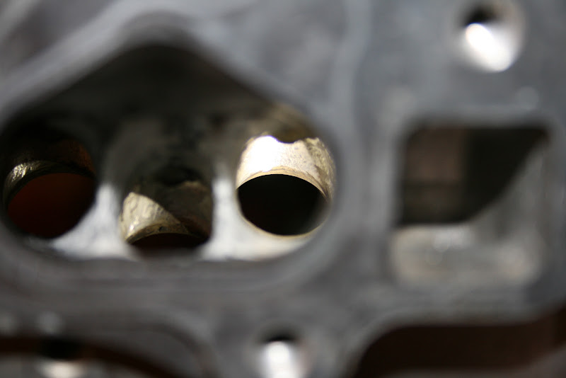
So this is a ( not very good ) cross section of a mold of an AE101 head over the top of AE111 pistons. It's not very good because I have to thin the silicone to get it to flow out and it's hard to work with like that. I would normal do this at TDC, but these pistons stand just BARELY proud of the deck, so this piston is positioned down the bore to simulate a 0.75mm headgasket. The volume this mold fills is sometimes referred to as the "clearance volume".

This mold is cross-sectioned down the middle. On the left is the center intake valve, split in two. On the right it gous between the two exhaust valves. At the bottom you can just barely see the indentation in the mold made by the dowe of the AE111 pistons. This shows how short that dome really is. On the exhaust side you can see the prominent squish, and how far the dome is from it' making a small volume between the dome and the squish. When the cross-section of the chamber gets smaller it slow the travel of the flame. If it's small enough the flame won't propogate, and you get squish! half-assed squish is bad. Well executed squish is good!

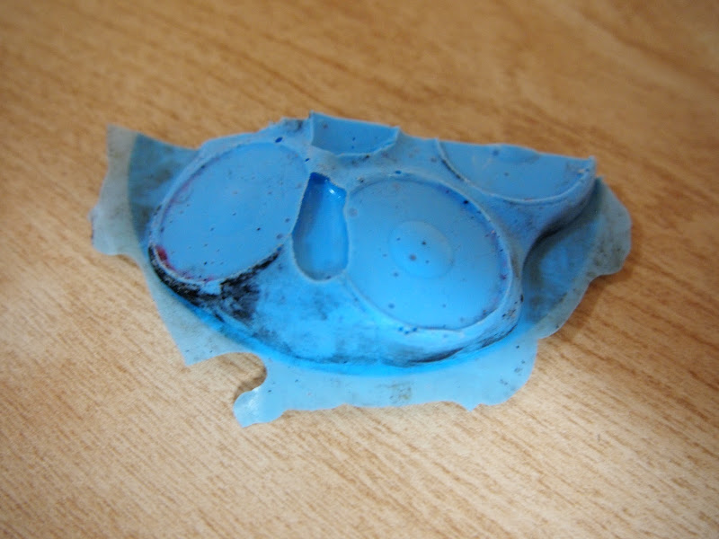
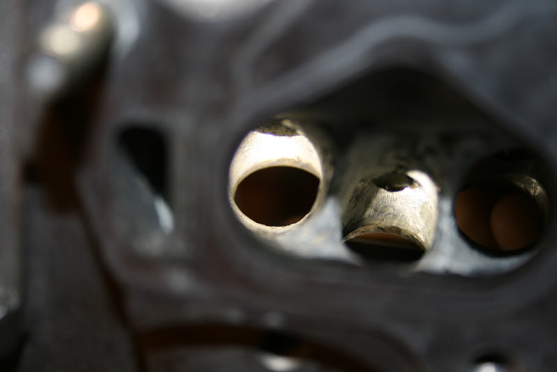
This second picture is a top view of this mold. Here you can see the silicone didn't flow well betwen the intake and exhaust valves. That's fine, we're looking elsewhere in the port anyway. The prominent squish on the intake side is evident here.

This third picture is a cut made between the intake and exhaust valves. On the left you can see the dome stops well before the curve of the wall of the head. Otherwise the cross section of the volume is quite good from the spark plug, which is on the far left, across the dome. Once again, for the compression ratio that can be achieved from these pistons they offer a damned good clearance volume geometry.

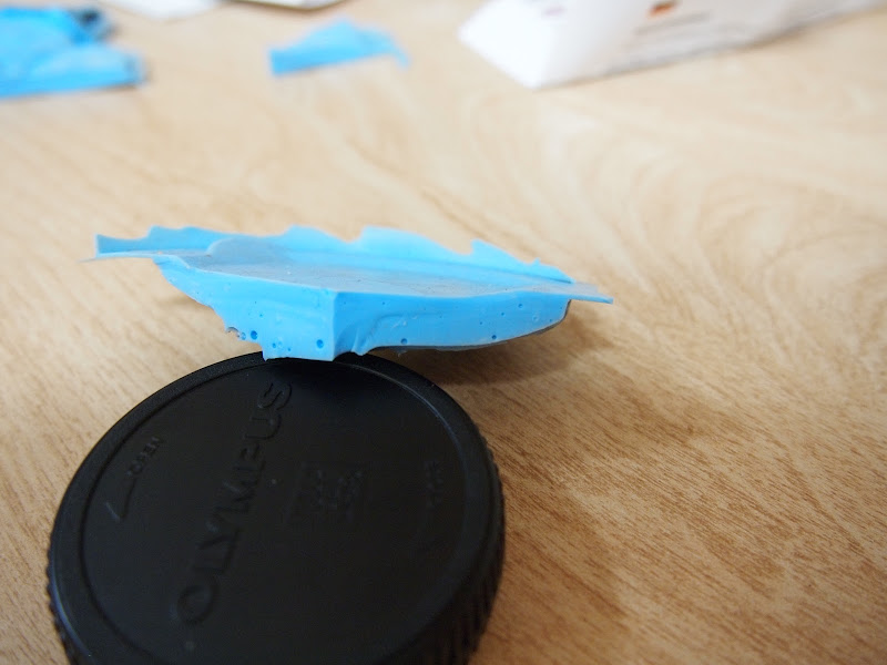
I flipped this piece over to show the profile the piston dome follows. The cut on the left is the bisection of the mold. The cut on the right goes from the spark plug down the center of the intake squish pad between the center valve and a side valve. The squish there is very prominent. Just to the left of it is the profile of the piston dome. I have heard some say that the cross section leading from the dome to the intake side of the clearance volume is insufficient for flame propogation, specifically on AE111 heads. This shows the cross section is maintained rather well through this area. This is very similar on the AE111 head. This cut also shows the clearance allowed between the AE101 head and AE111 piston.

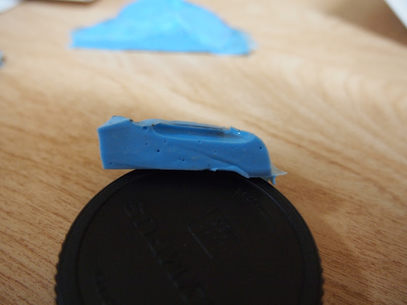
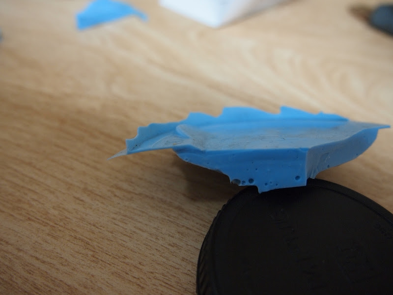
This last picture is of the bisection cut of the same mold piece shown above. The exhaust side squish is on the left. Here you can prominently see the exhaust valve relief. It is worth looking at the angle of the relief. This actually says something, believe it or not. On some pistons the valve relief is machined parallel to piston travel. Others, such as this one, is parallel to valve travel. My assumption is that this is based on the relationship between piston and valve travel. It is also worth noting that the clearance volume retains a respectable cross section in a section that tends to be compromised.

What does all of this mean? It means the AE111 piston do very well with the AE101 head. It also shows many areas for improvement, particularly where the dome does not extend to the walls of the bore. This would involve changing the shape of the squish pads and the combustion face of the head quite a bit. The advantage of the AE101 head over the AE111 in this regard is that there is more metal to work with to do so.

So we're going to look at some different pistons for build B ( not this engine but the next one ). Plan of action here is to determine how deep valve pockets need to be based on the profile of these camshafts. This will dictate much of the shape of the dome. The remaining sections of dome will be squish, and the head and dome will be modified to create a cohesively designed clearance volume.

burdickjp
burdickjp GRM+ Memberand New Reader
3/19/13 10:52 a.m.

I ordered up some Clevite rod bearings, as they're a bit thinner than the thinnest OEM bearings, which allows me to widen my rod bearing clearances a bit.

So I measured them up, and came out with 0.046mm clearances all around. Fantastic. I then plastigauged to check, and came out even across the board.

Installing rods is best done using the bolt stretch method.

Here's a good looking bottom end.

Jerry From LA
Jerry From LA Dork
3/19/13 11:16 a.m.

Is your dial indicator fixture designed specifically for measuring bolt stretch or did you adapt something else?

burdickjp
burdickjp GRM+ Memberand New Reader
3/19/13 2:26 p.m.
Jerry From LA wrote: Is your dial indicator fixture designed specifically for measuring bolt stretch or did you adapt something else?

It's designed specifically for that. I'm using a 2" indicator to allow me to measure OAL, but otherwise they're available from Summit.

1 2

You'll need to log in to post.

Our Preferred Partners
cSUHVAdkCXbWHvCpkYxlYZRZDgXqULRY5b9vAnrYKNYRIZqR8MHIkzyY6uhtglPj