MIG welding wire is normally .023" or .035" If you need something that small and round in a pinch.

MIG welding wire is normally .023" or .035" If you need something that small and round in a pinch.

RacetruckRon said:MIG welding wire is normally .023" or .035" If you need something that small and round in a pinch.
Unfortunately, all we have is the 0.035" and it is too big; I tried.
The drill rod has arrived from McMaster, so I should have a report soon on whether I got that right. It looks like a needle.
damen

Good job making progress with wiring!
Your injector color coding: are they switched high or low? Whatever is the controlled signal, color code that wire. The common can be spliced together with the others relatively close to the terminations and a common color. I presume you're following the Infinity wiring diagram closely?
Knock sensor shielding: you'll probably be fine with your wiring method here. The proper way isn't all that hard, and the shield should be grounded to the "Sensor Ground" through the ECU. If you route the wires away from noisy things (coils, big +12 or ground sources), then the sensor should read fine.
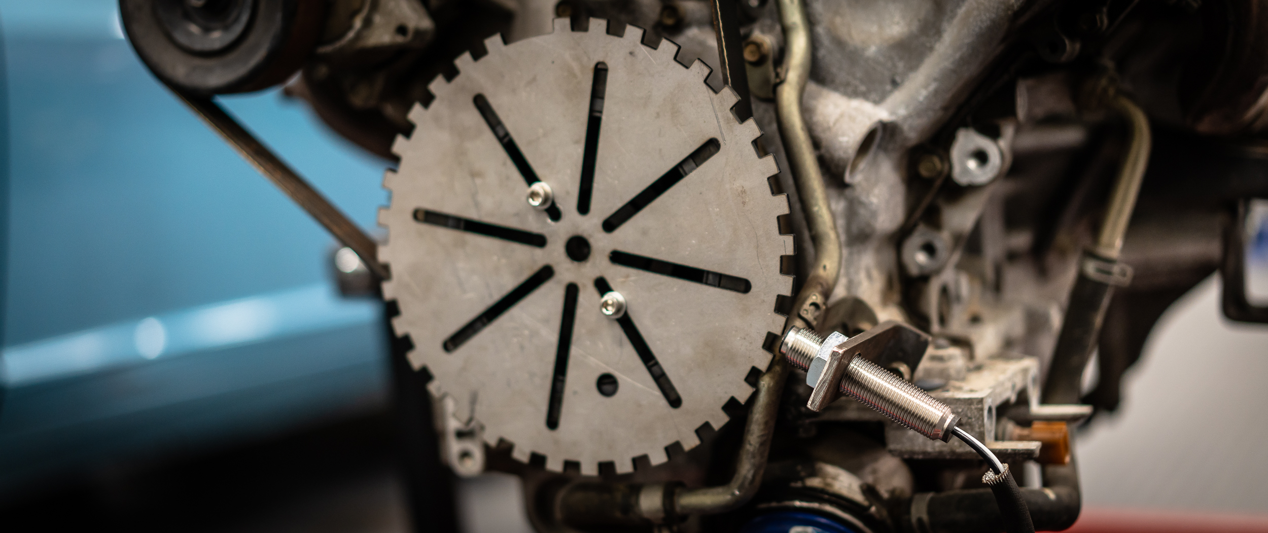
.030" runout in your tone wheel is a lot, and I'd encourage you to get it dialed in closer. You want that VR signal to be as good as it possibly can be or you'll start seeing trigger errors at higher RPM.
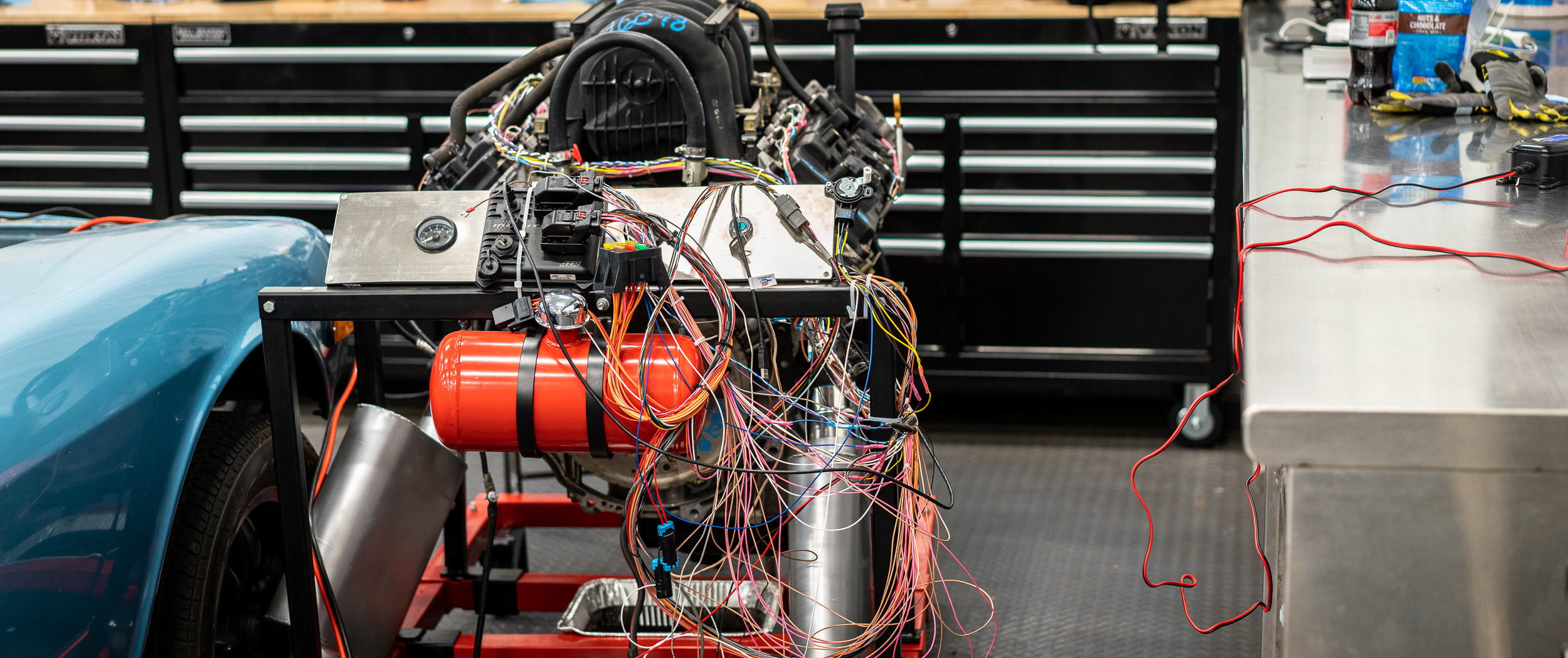
I ADORE your shame spaghetti. That specific folly is what drove me to build my harness in situ. And now you have learned, padawan. ![]()
Keep going.
Mezzanine said:Good job making progress with wiring!
Your injector color coding: are they switched high or low? Whatever is the controlled signal, color code that wire. The common can be spliced together with the others relatively close to the terminations and a common color. I presume you're following the Infinity wiring diagram closely?
Knock sensor shielding: you'll probably be fine with your wiring method here. The proper way isn't all that hard, and the shield should be grounded to the "Sensor Ground" through the ECU. If you route the wires away from noisy things (coils, big +12 or ground sources), then the sensor should read fine.
.030" runout in your tone wheel is a lot, and I'd encourage you to get it dialed in closer. You want that VR signal to be as good as it possibly can be or you'll start seeing trigger errors at higher RPM.
I ADORE your shame spaghetti. That specific folly is what drove me to build my harness in situ. And now you have learned, padawan.
Keep going.
Thanks, man!
Injectors are switched low. I just gave them their own color for the signal, then reused OEM injector power color wire for the power. If I were going from scratch, I'd go with red for the power, then some signal color. Your idea sounds good, too.
I'll get some nice Bosch knock sensors for the big engine build, then do some nice shielded cable for the wiring. I will try to make sure the routing is away from the noisy stuff, thanks.
It probably wasn't clear in my post, but I readjusted to get the runout within 0.005". I agree that 0.030" is a lot. You could see it big time in the video.
Consider me learnt-
damen

Did you check the inside of the exhaust manifolds for cracks, it's a real problem on these motors. My passenger side is cracked, I'll probably pull it off and weld it, or pull both sides and get some headers.
akylekoz said:Did you check the inside of the exhaust manifolds for cracks, it's a real problem on these motors. My passenger side is cracked, I'll probably pull it off and weld it, or pull both sides and get some headers.
Hey Tony-
I have not checked, but I appreciate the heads up. Honestly, these manifolds will only stay on the engine long enough to idle on the stand, then be removed for good.
Let me know how you get on with yours!
damen
Phew! .005" is much better and probably adequate for your purpose.
I don't know what you're doing for a crank position sensor mount, but if you're fabricating something, here's the rule of thumb: you should be able to lift the engine with the CPS mount. It needs to be sturdy. If it's a diving board, it will vibrate and cause you all sorts of grief with weird crank errors at harmonic vibration engine speeds. I see you've got something holding the sensor now, and I recall you wanted to change sensors. What's the word there?
I'm glad you mentioned that you're enjoying wiring. I like it too, for the same reasons. Methodical, quiet, clean. It's soothing work creating a wiring harness. Chasing down electrical gremlins is the opposite of soothing... that's why we do a good job here.
In reply to Mezzanine :
For this particular crank sensor mount, I'm using a 1/4" piece of steel angle, fittingly from the leftover scrap of the engine mount material :)
It unfortunately does quite resemble a diving board. I will take your advice and come up with something better for the next revision.
Part of the reason it looks like this now is due to placement of the trigger wheel: it's all the way to the front, far away from the block. For the final build, I'll be using a different damper and a trigger wheel BEHIND the damper/pulley. Then I'll switch over to some OEM VR sensor that's more appropriately sized and mount it robustly.
I hope my work is a good job; unfortunately we won't truly know until the key is turned...
Thanks!
damen
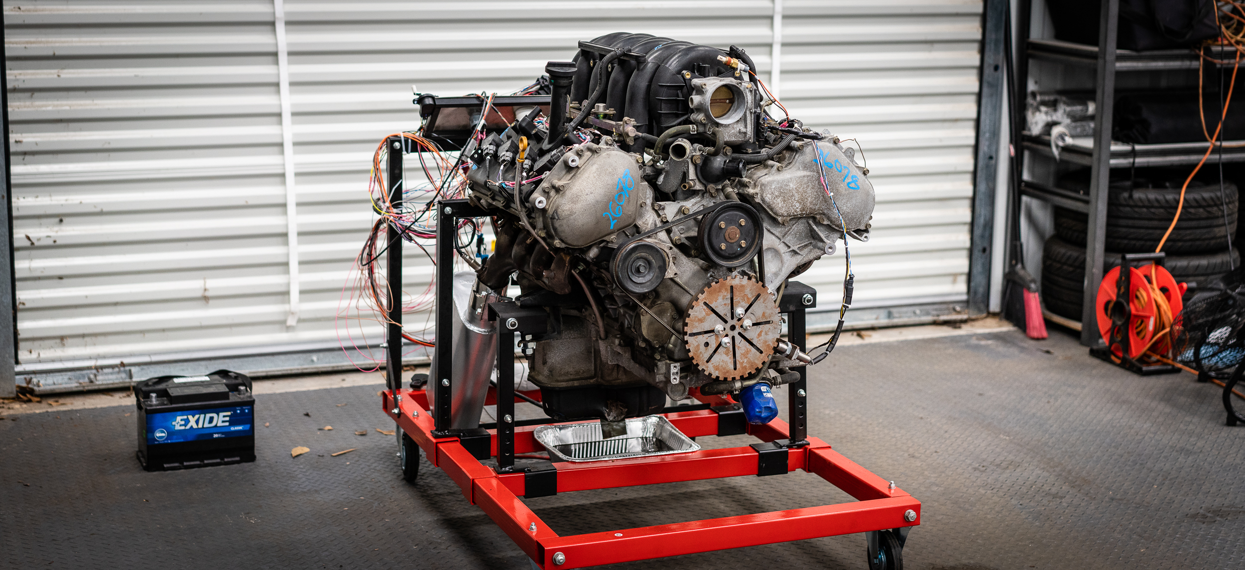
Hey everyone-
It's been a process of working through the setup, step by tedious step, but it's a runner.
I won't bore everyone with the details, but I'm glad this is complete.
damen

Nice!
I like the sound and throttle response so far :-)
Gustaf

In reply to badwaytolive :
That sounds really good!

That seemed to work super well.

Nice milestone! Congrats!
Thanks, everyone.
I think my next step will be to get the wiring on this harness fully cleaned up. Wires the correct length, everything labeled nicely, etc. That way, when I make the next harness for this motor, I'll have a nice reference that I know is functioning.
Then tear everything apart...
damen
BERK YES
That sounds incredible. Congrats on first start. Get that harness dialed in now.

That really sounds nice.
Hey everyone-
I sort of skipped a bunch of posting during the stand-harness-building because the details didn't seem interesting at the time, but for completeness, I'm backtracking a bit to fill in some holes. I hope y'all don't mind.
One of the reasons I chose the AEM Infinity 708 engine management system is its ability to run two wideband oxygen sensors with internal control.
Wideband sensors sold separately. Obviously. So I got two fresh Bosch LSU 4.2 sensors and guess what?
They don’t plug into the AEM Mini-harness I paid big money for.
Nope.
You need an $85 “adapter harness” to plug the Bosch sensor into the DTM plug on the harness.
$85 EACH.
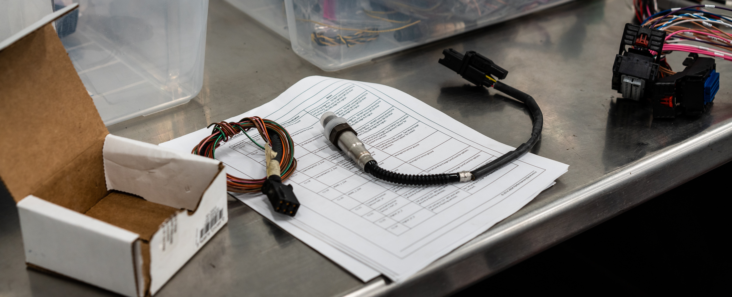
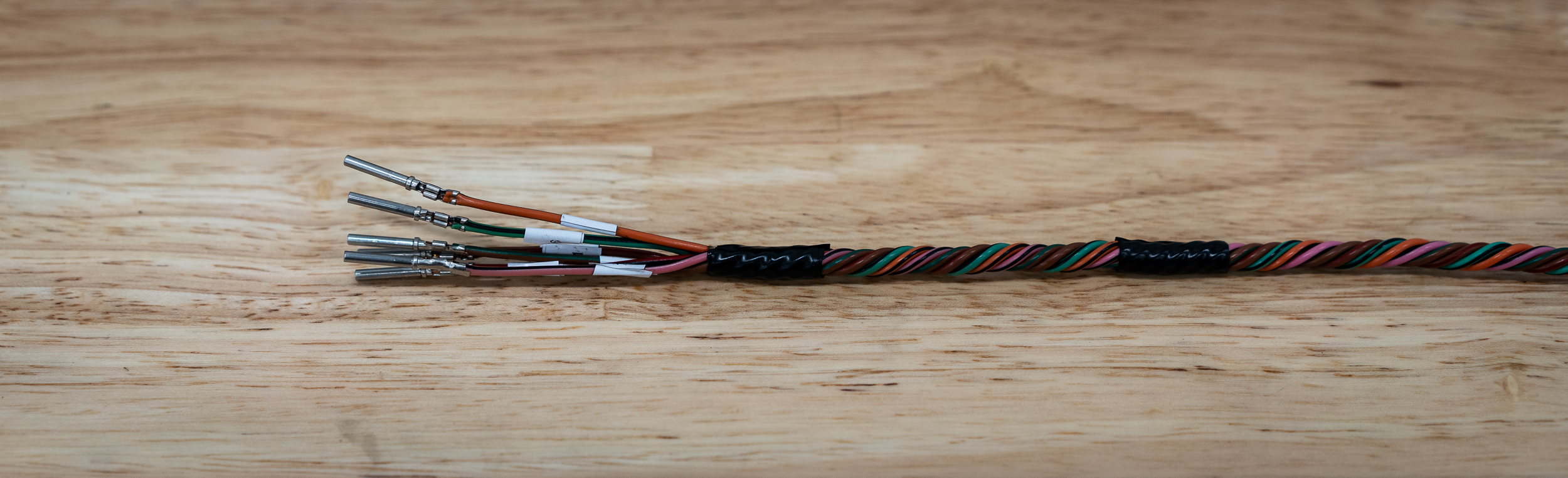
Not real happy about that, but there’s nothing secret or particularly magical about the adapter, which is just six wires that go from one type of plug to another. So I decided to make my own.
I ordered the two DTM mating plugs I needed to go to the AEM side. That was $3.98. I had the Bosch side connectors from the junkyard harness that had some wire still attached. So I used that.
One of the issues that did need worked out is which wire went where. I spent sort of a long time with wiring diagrams and the ECU pinout to make sure that I was putting the wires in the right place.
Unfortunately I won’t know if it’s right until I fire it up.
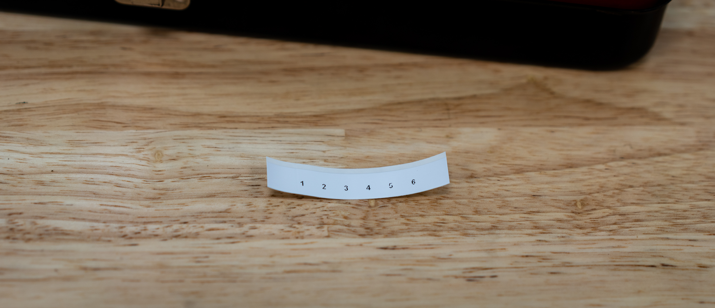
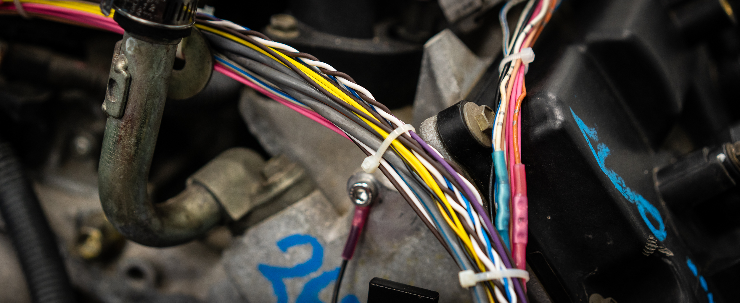
I did my best to label everything as clearly as I could, both on the connectors and the wires themselves.
Like I said before, I’m not very impressed with this label printer. Not sure if you can tell here, but it looks like a printer running out of ink. Which it’s not.
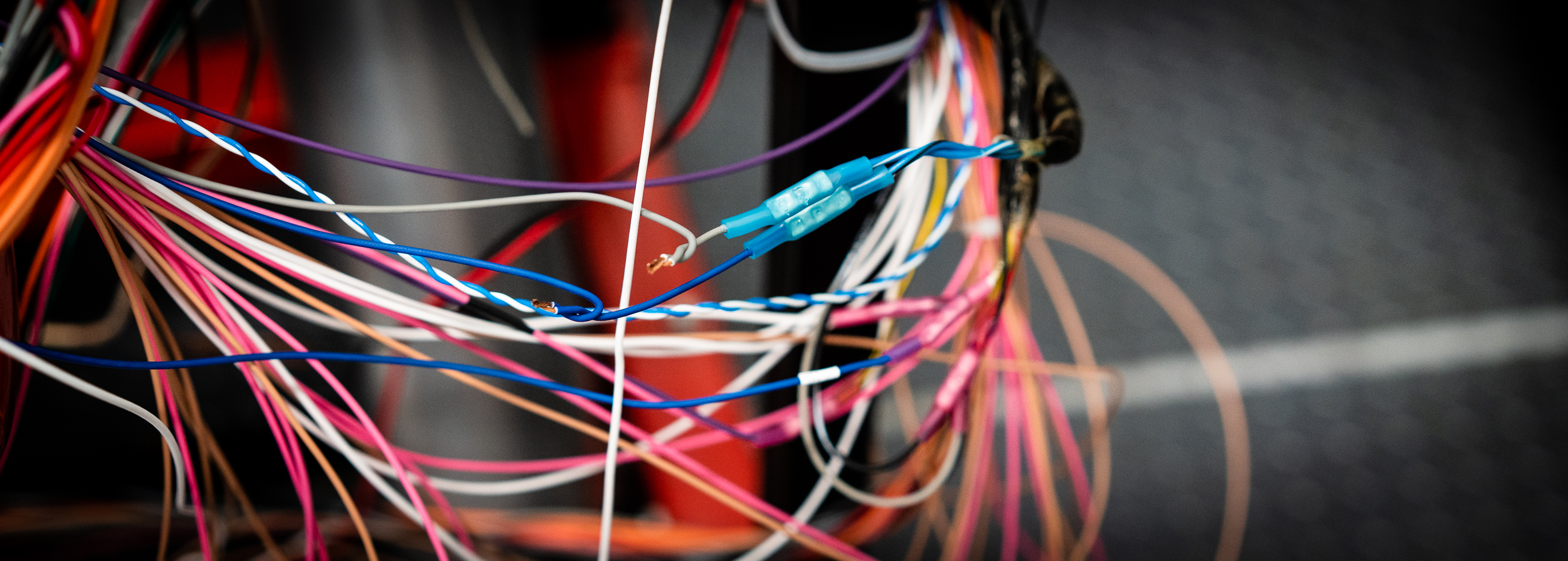
Okay, so I wasn’t able to get any in-progress pictures, but I made an attempt at concentric twisting. That means wrapping the wires in a way that provides the most flexibility and smallest cross section possible. There’s a specific way to do it to get everything to lay nicely.
You start with one wire running straight, then you wrap 6 wires around the outside of it, sort of like you see below. The next layer of wires will twist the other direction, and it requires 12 wires to sit nicely. Then the next layer is 18 wires and so on. The number of wires in each layer is so important that real motorsport wiring harness builders will add “filler wires” (wire that isn’t connected to anything) to get the right count.
Well, this particular harness adapter has 6 wires. That means, with 1 center wire and 6 wires for a complete first layer required, I needed to add a filler wire for a total of seven.
But this is just for the stand. It won’t be on the real car build. It’s not getting boots and epoxy and heat-shrink and self-wrapping labels.
I just made do with what I had to practice. I certainly won’t submit it for judging, but I was pretty happy with how it came out.
This is how it came out before attaching the AEM-side DTM connector:
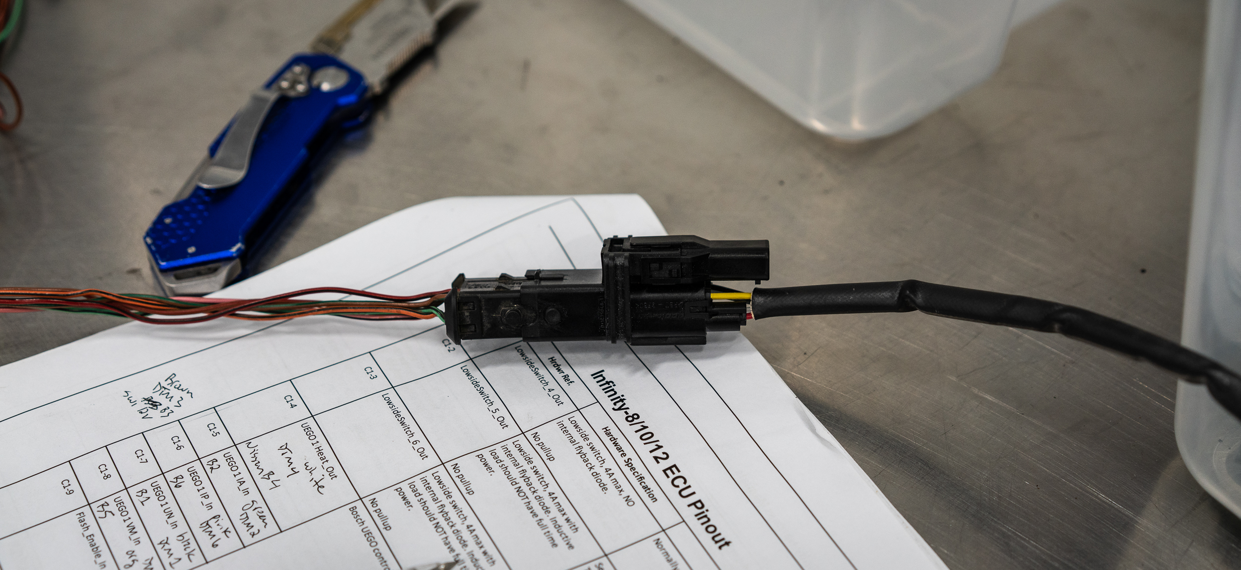
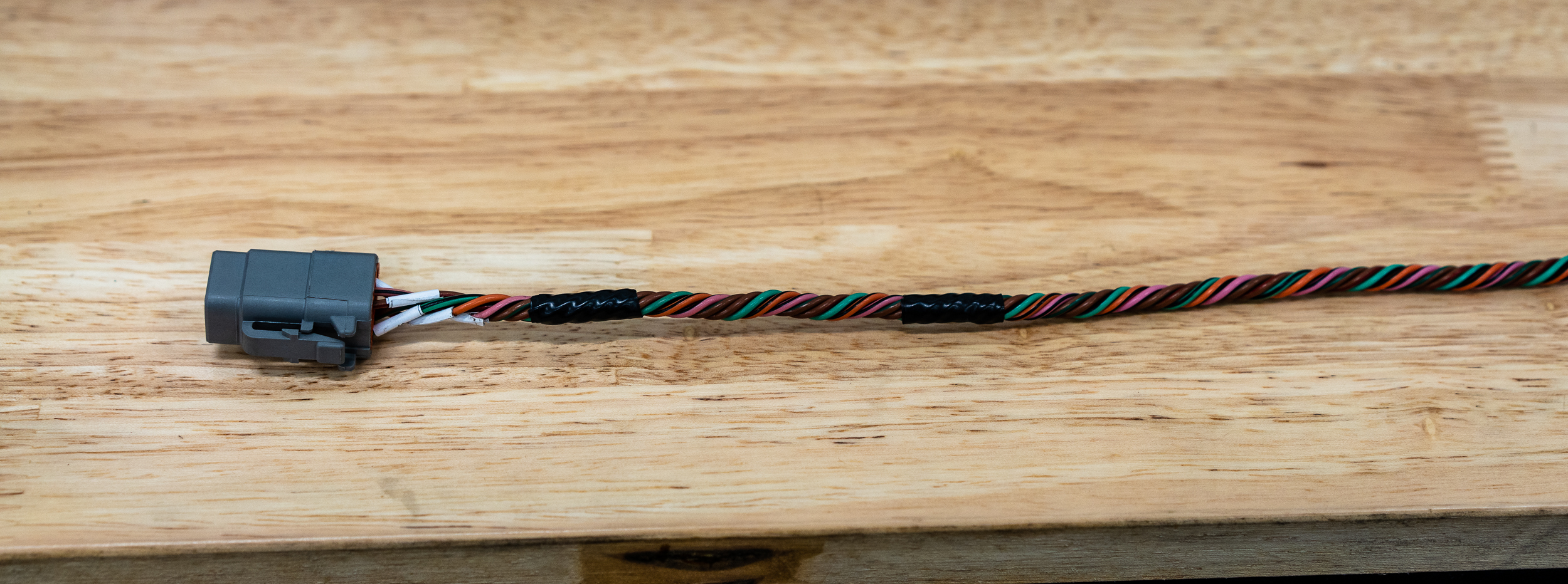
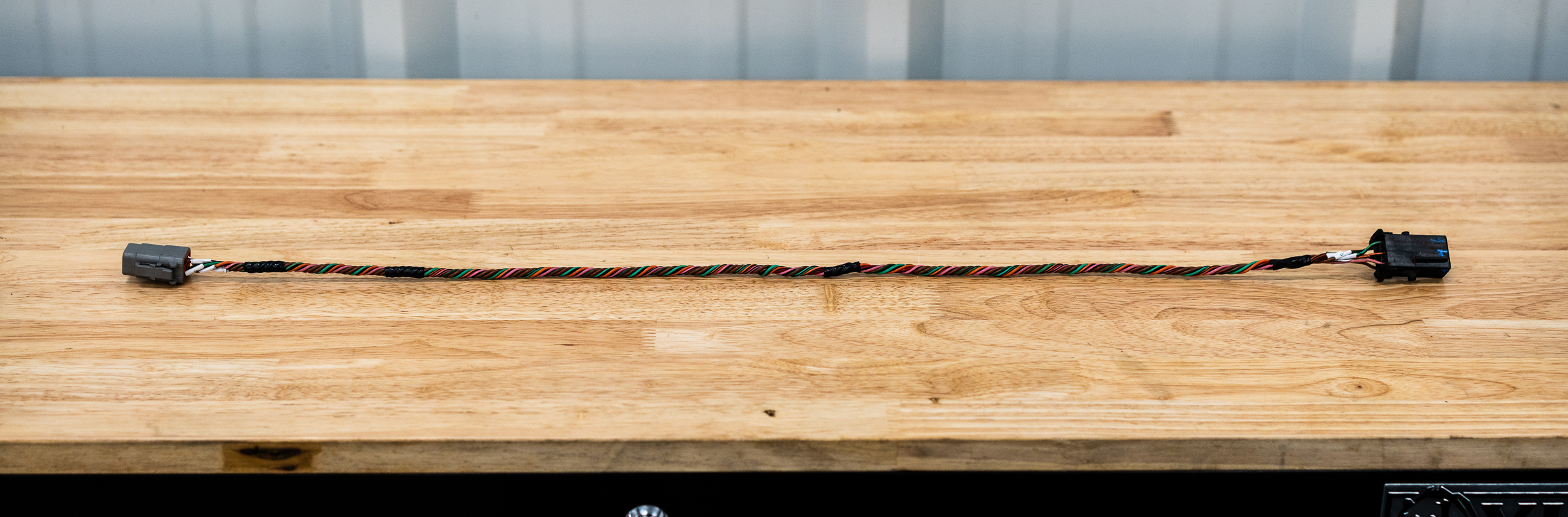
Then I added the connector and it’s ready to go! I think.
I plugged it into the wideband sensor, which I installed, then to the ECU.
If this works out (for both sides), I will have saved myself $180. Woohoo.
I’ll need it later.
Thanks for reading!
damen

That is a damn gorgeous twist.
Yeah, that's sweet. I might have to mess with doing that on some of my wiring.
Cheers, dudes.
For anyone trying this themselves, I would strongly recommend adhering to the 1-6-12-18-.... layer counts. I did 1-5 and it was difficult and didn't come out as nicely. Too much twisting to get them butted up next to each other, which made it less straight and clean than it could be. I'd throw in an extra filler wire next time.
damen
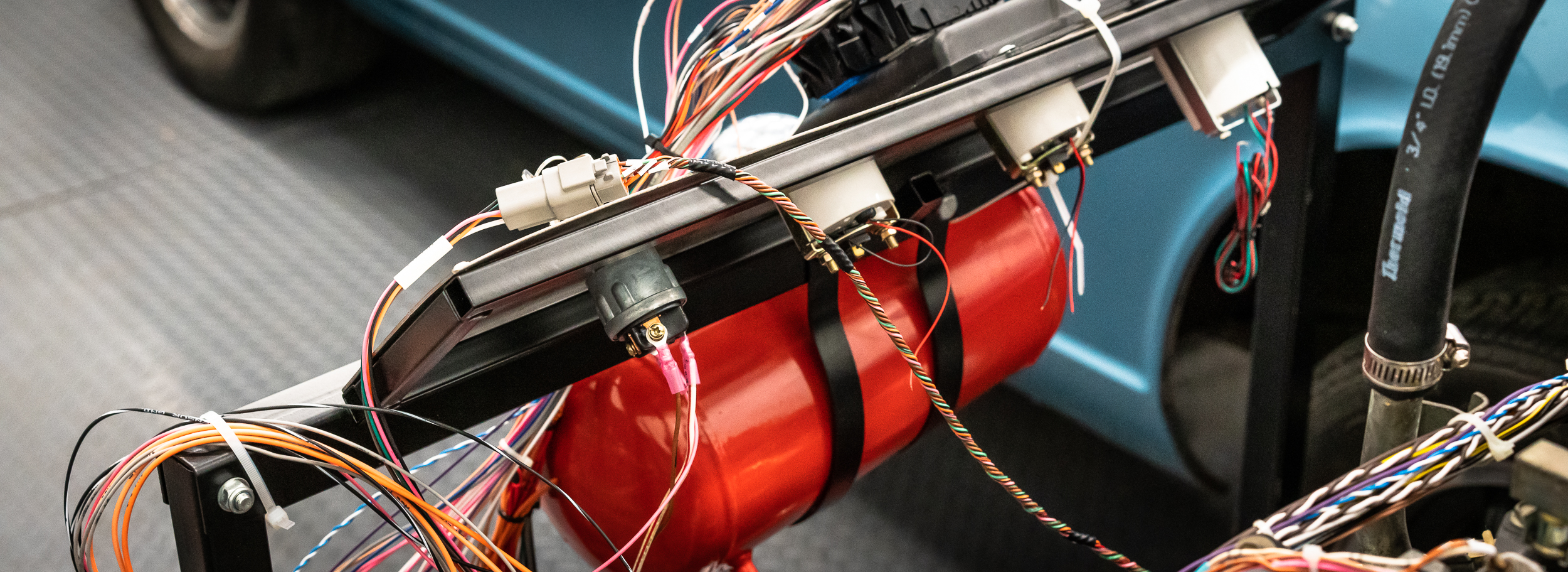
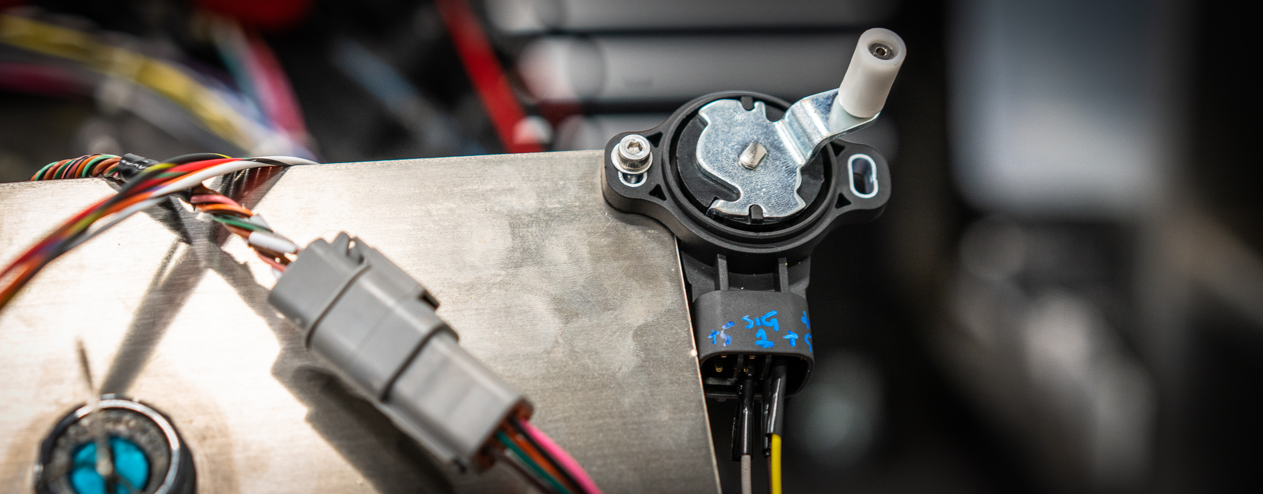
With the wideband sensors plugged in, I only had one sensor left to add in: the accelerator pedal position sensor.
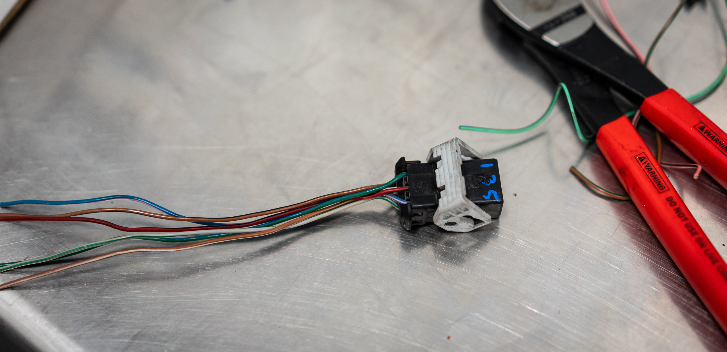
Well, I don’t have the stock Nissan Titan pedal setup, which has the pedal sensor in it, so I jumped on eBay to see what might work as a replacement.
My favorite find was actually a Chinese replica part for a Nissan 370Z (keepin’ it in the family!), so I ordered one for $17. It’s unique in that it has a little actuator arm with a bearing on it that I can use to rev the motor. Lots of the other sensors didn’t have such a nice mechanical portion. In the meantime, I found a couple images online with some hints to the pinout, but nothing solid.
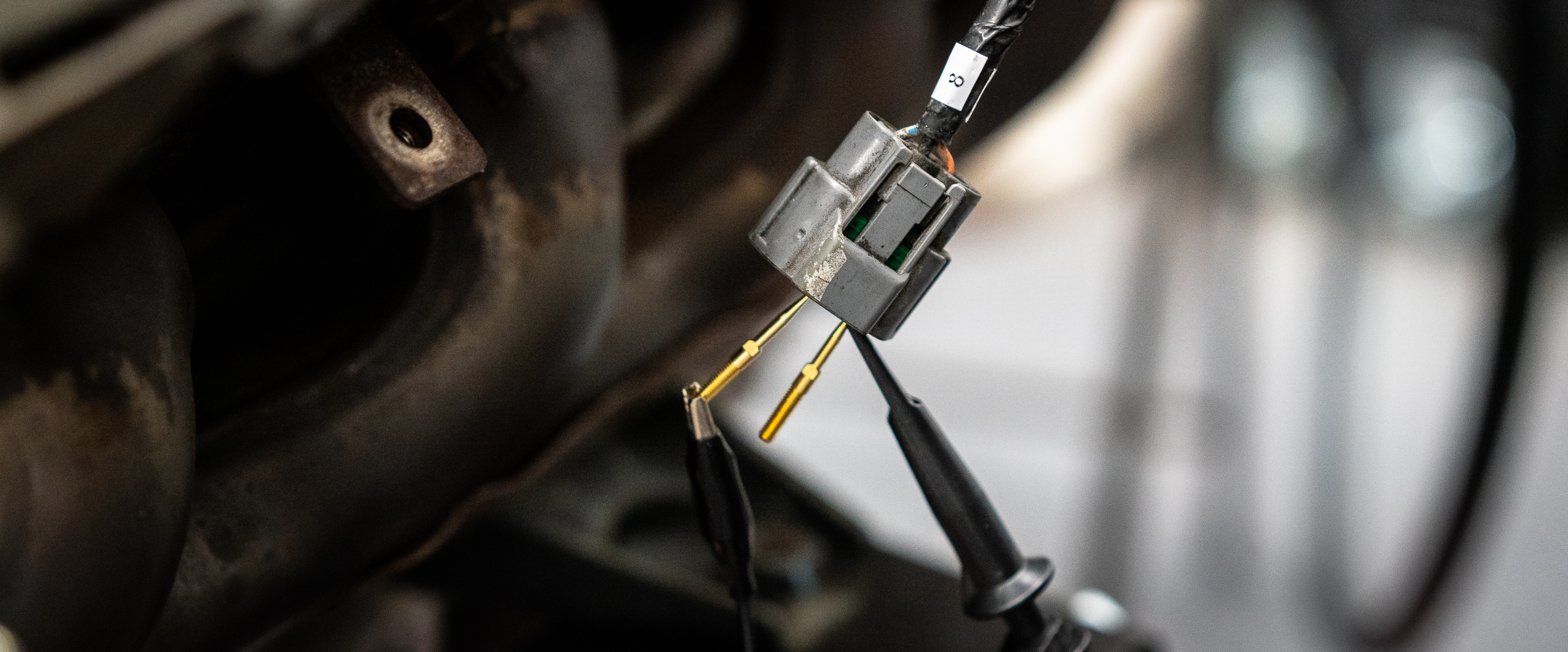
The part came in and I used my bench testing setup to figure out which pins did what. There were 6 pins. There are two sensors in the unit, each one with its own power, ground, and signal. I figured it out eventually and labeled the actual sensor housing with a paint pen and hooked up one of the sensors. I only need one signal for the ECU.
And here it is, bolted to the test stand, with the three wires hacked in.
With that last sensor sorted, I was ready to plug in the ECU and see what was what!
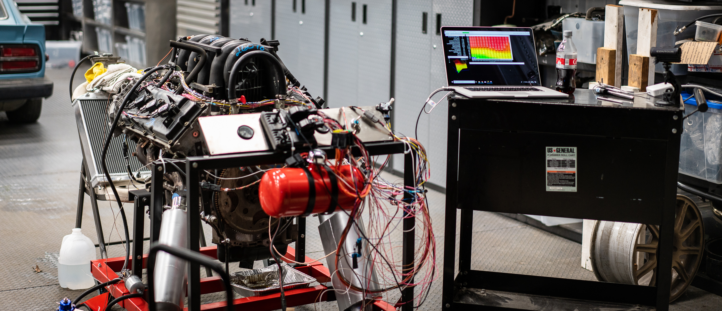
So I hooked up the USB cable from the AEM Infinity 708 ECU to my laptop and turned the key.
Connected!
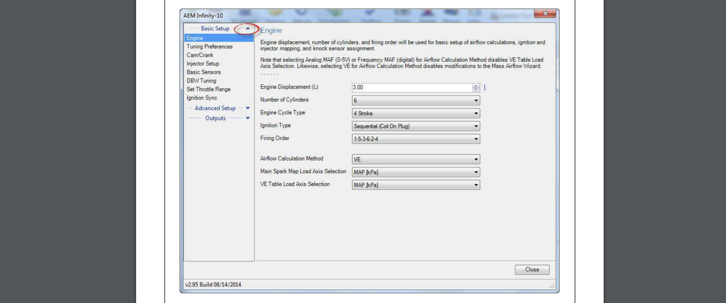
The AEM uses a bunch of wizards to get started. I’m not a huge fan; they’re finicky and seem non-deterministic at times, losing configuration changes every now and then, etc. I’d rather just have tables to edit rather than drop-downs and abstracted controls.
Here’s a shot of one of the main setup wizards from the AEM Infinity Quick Start-Up Manual:
There’s a wizard to setup the drive-by-wire system. It walks you through some steps where you hold the accelerator pedal open, then closed, then at 25%, and it opens and closes the throttle body, reading the feedback from the throttle body position sensor.
Then it’s supposed to use those first couple steps to do an auto-calibration on the electronic throttle body.
But it didn’t. It said, "Error, the throttle body signal did not change (changed less then .5v) ". Then it recommended I check my wiring.
Grrrr.
I could see that the throttle body position sensor was working correctly in the first three steps (there were some real-time gauges showing me the changes), so I thought maybe I had the motor wiring backwards, so I tried swapping those.
Beautiful, I know.
But that didn’t work either.
I had some time between shop days to email AEM’s support and scour the interwebz for a hint. AEM support never got back to me, but I did find a thread that talked about wiring up a drive-by-wire setup. They specifically mentioned having to wire up both sensors in the throttle body and both sensors in the accelerator pedal. I’d only done one of each.
The next time I was out, I wired up the second sensor on both and this time, the calibration completed successfully! So anyone reading this in the future, you absolutely need 2 signals for actual throttle body position and 2 signals for the accelerator pedal position. From sources I’ve talked to since, it seems this is pretty standard; ECU manufacturers want to make sure there’s a backup for these two. Makes sense.
Okay, that meant I could crank it over to check for spark! I didn’t have any fuel hooked up yet. I figured it’d be easier to troubleshoot any spark problems first.
I’m glad I did that.
I tried using an inductive timing light that Nik had on the shelf, but I could not get it to flash. Either that meant I had no spark, or it meant I had the light hooked up incorrectly.
I first pulled the coil and plug out and cranked it while holding the plug against the block.
No spark from the actual plug.
I wanted to double check that the coil wasn’t generating voltage to the plug, so I came up with this convoluted (and admittedly not too safe) arrangement to try to get the light to show me something.
Imagine that, it didn’t work.
At this point I was pretty comfortable saying that the coil was not firing. None of them were.
I double checked the coil ground and power. They were good. Here’s the ground point on the back of the head:
I wasn’t seeing the crank trigger output in the ECU diagnostics tab either, which was strange. And probably one of the reasons I wasn’t getting spark.
So I disconnected the DT plug for the crank sensor and checked the sensor side with the oscilloscope. It looked fine; I was getting a nice signal, just like before.
Well, when I went to reconnect the plug, I noticed the pins were awfully deep in the connector. Like too deep to be contacting the sockets. Sure enough, I got my pliers and pulled them into the right position, confirmed by a nice click. I had just done that wrong the first time.
Now the ECU was seeing the crank signal- woo!
But still no spark.
One thing that was rattling around in the back of my head was the cam trigger configuration. In order to run a fully sequential injection and spark setup, the ECU has to have a crank trigger signal as well as a cam trigger signal. I’ve seen a lot of talk on the AEM support forums about which trigger configurations are supported. I confirmed that my crank trigger (a 36-1 tooth wheel) was fine, but I was a bit concerned about the goofy Nissan cam trigger setup.
The documentation said that for universal applications (which is me, since they haven’t created firmware for my specific engine), the cam trigger must be one tooth only. Well, mine has 10 notches on the back in a I, III, II, IIII (yes 1, 3, 2, 4) at each 90 degrees. I guess that wasn’t going to work.
No problem though. AEM does have “Semi-Sequential” firmware that can work as long as you have a missing tooth on the crank trigger to tell the ECU where it’s at in the rotation. I have that. The difference is that the injectors will fire every revolution (for half as long), and the coils will fire every revolution (wasted spark). You actually don’t lose that much performance, so it certainly wouldn’t be a problem for my test on the stand.
So I loaded the semi-sequential firmware onto the ECU and re-did the configuration wizard.
Still no spark.
I confirmed that the ECU wasn’t sending a signal to the coil by hooking up the oscilloscope to the connector. Nope, no signal.
I emailed back and forth a bit with the AEM tech support. He went through some stuff with me, but what he was saying didn’t make a lot of sense regarding my application. He admitted to being limited help because my engine is not a supported application.
He did point me to their output testing firmware though. That was yet another firmware to load on the ECU that would allow me to manually trigger the outputs to the coil connectors to confirm that my wiring was correct. If I could confirm that, then I’d know I had a software configuration problem.
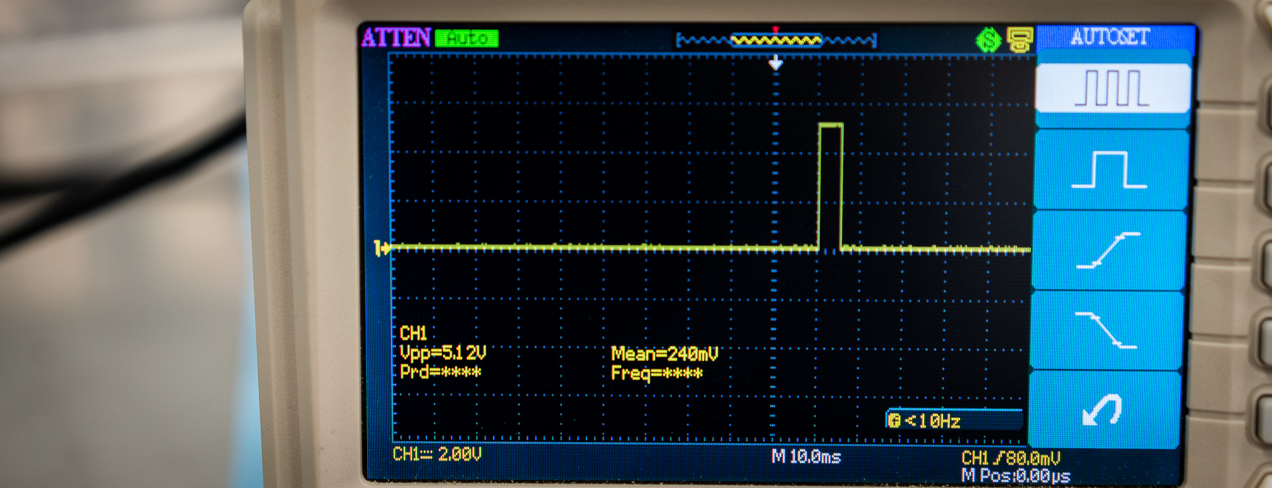
With the scope hooked up, I loaded the “Output Diagnostic Troubleshooting” firmware onto the ECU and triggered the coil output.
Behold! A signal!
That was actually great news, as it meant that my wiring harness was correct.
But it still didn’t tell me why I couldn’t get spark with the semi-sequential setup.
Just by chance, as I looked over the engine for inspiration, I remembered that the AEM tech mentioned to unplug the cam sensor when I loaded up the semi-sequential firmware. I sort of forgot that bit of advice as I assumed the semi-sequential firmware would ignore the cam sensor, since it wouldn’t be used.
I unplugged the cam sensor anyway.
AND IT WORKED. I CRANKED AND HAD SPARKS. WOOOO!!
It’s strange to me that AEM would still look at the cam sensor input in a semi-sequential setup, but apparently it was confusing the ECU enough to make it not sync. I haven’t been too pleased with the software on this ECU, but it’s early days. Maybe I’ll be more impressed with it later?
Anyhow, I could smell some whiffs of fuel being injected, which I’m sure was leftover in the rails, so it seemed the injectors were firing too.
That meant it was time to button up the last few things before I gave it a real crank attempt to start it up!
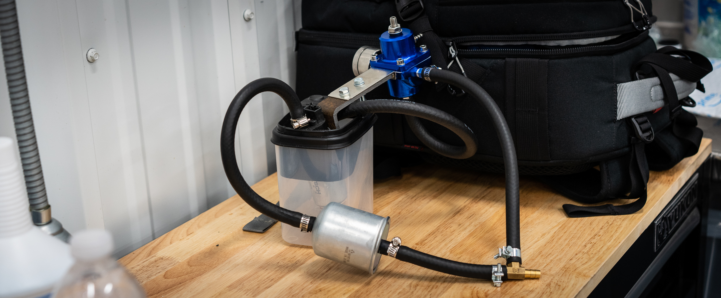
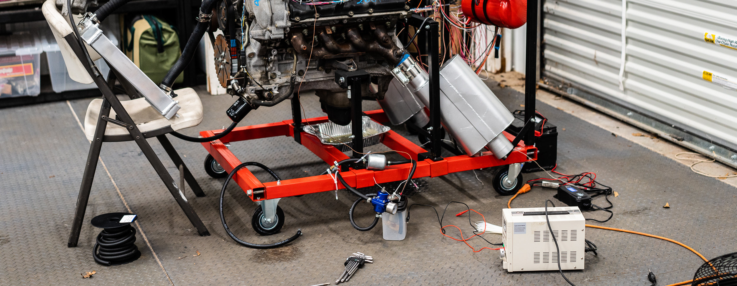
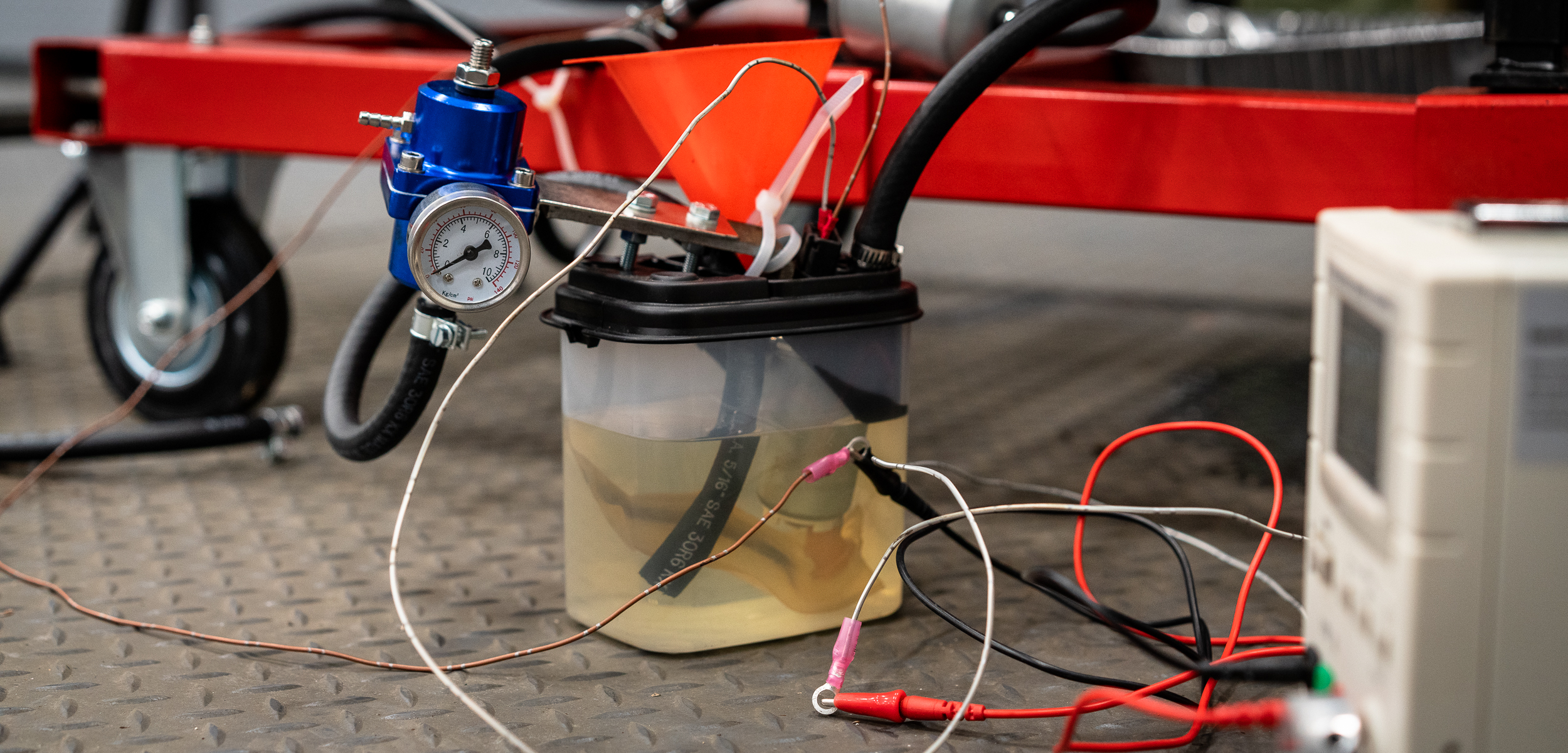
I did have a few minutes to put together my fuel pump, filter, regulator, and “tank” setup. I got a $13 adjustable fuel pressure regulator off eBay, an $8 filter, and a borrowed fuel pump from Nik. And some tupperware.
I present to you: a fueling setup to raise the hairs of professionals, fire marshals, and burn units everywhere.
I’m sure it’ll be fine. Right?
Thanks for reading!
damen

+1 for sketchy fuel delivery systems!
I am SO bummed to hear your difficulties with the Infinity software. I had a really similar experience with it many years ago when they were new on the market, and I'd hoped that had changed or improved over the years. For what is considered one of the gold standards in stand alone ECUs, it's disappointing. In fact, the issues you've been troubleshooting are the exact reasons I chose the ECU that I did: PE3. They make diagnostics super easy, and setup too.
Anyway, three cheers for sketchy wiring, and even sketchier temporary fuel delivery methods. Whatever it takes to complete the test, right?
Did the wideband preheat correctly? I feel your pain in trying to reverse engineer pin-outs on all these things. I've been through the same many times, and it's always a crapshoot.
In reply to Mezzanine :
Ya it's a bummer for sure. Makes me wish I'd just gone with the Engine Lab EL129. It's a lot more DIY on the software and modeling side, but it's cheaper, gives you more flexibility, and uses LSU 4.9's instead of the 4.2's.
Ah well, live and learn I suppose. I'm hoping that once I'm doing real setup that I'll get used to it and it won't bother me :)
The PE3 price is certainly attractive, but I'll admit that I don't know anything about it; what were some of the criteria that made choose that?
The wideband sensors both seemed to operate happily, so no problems there I think.
damen
Big day.
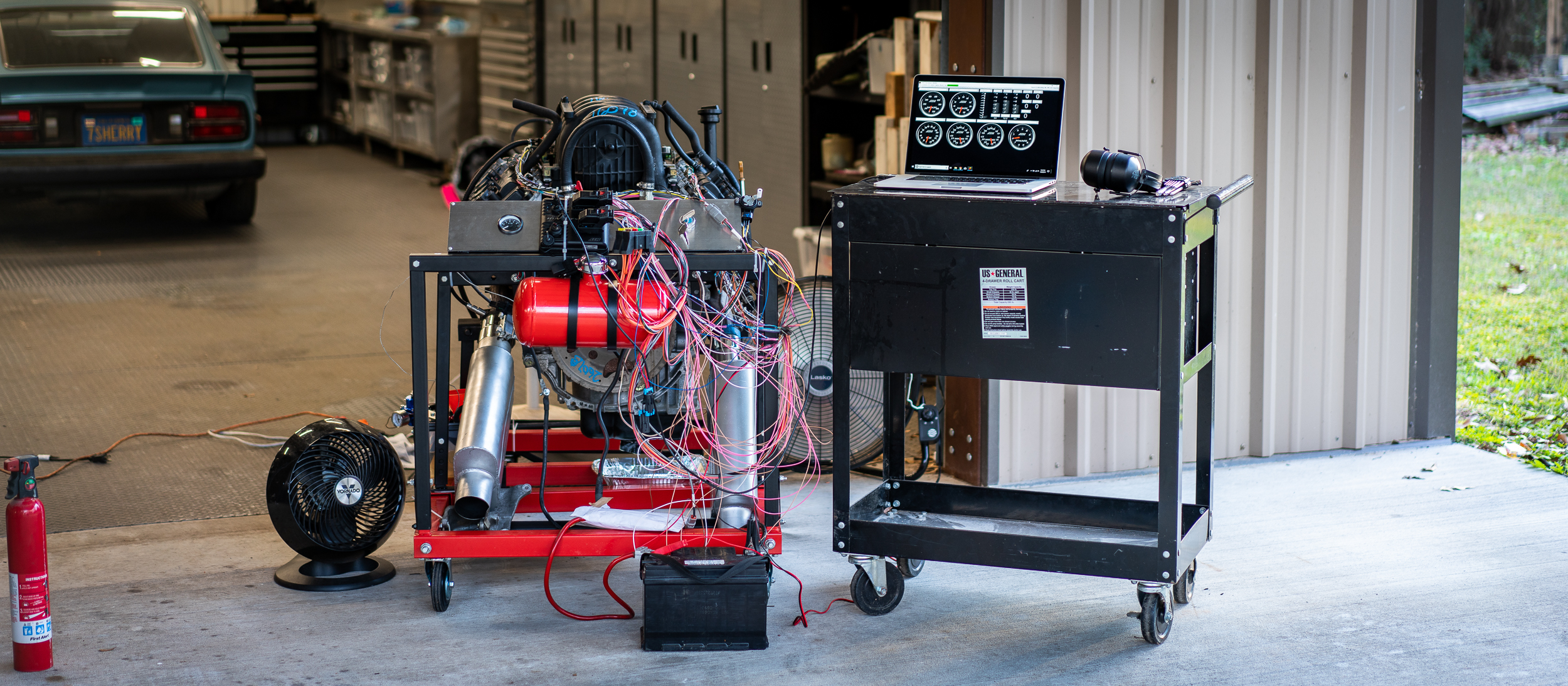
Gonna try to fire up the motor on the stand for the first time!
I started the night by running to the gas station to get a gallon of gas. And some snacks.
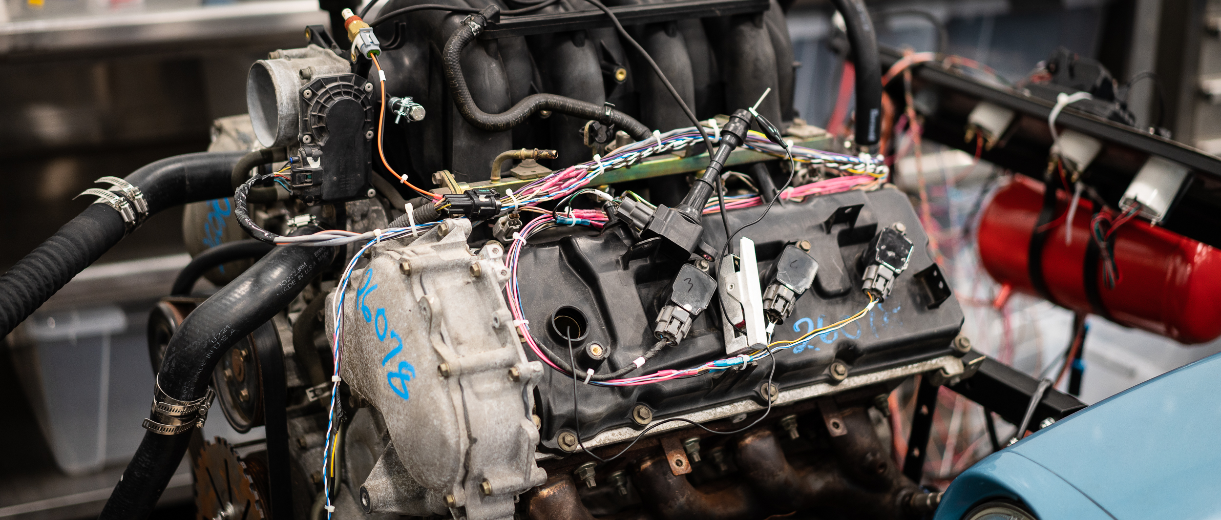
I got back to the shop and unhooked everything from the bench and cleaned up the wiring so nothing was touching the hot or spin-y bits.
Then I rolled it over close to the door for final setup. I still needed to hook up all the fuel and water stuff.
I started with the radiator. I’d already cut the hoses to size, so this was pretty simple to just hook up the hoses, fill with water (holding the upper hose nice and high and filling through there), and tighten the clamps.
Then it was on to the fuel. As previously written, I had the pump/”tank”/regulator/filter all set, I just needed to run it to the fuel rails and test.
I originally wanted to try running the fuel pump on the variable power supply, just so it didn’t go crazy with the full battery power applied, but that couldn’t supply enough power.
So I just hooked it up to the battery.
No problem.
I had to adjust the regulator a bit to get to 50 psi, but no drama there. I kept the fire extinguisher close, though. No need to tempt fate.
With that, it was time to turn the key!
Nik helped me roll it outside so as not to fill the shop with fumes.
Well, it cranked, but no fire.
I did get some pops and bangs with lots of black smoke, but it never quit fired up. It would catch a little, pop, bang, smoke, then crank, crank, crank.
The LambdaTargetCrank Table was set at 0.2, which is crazy rich, but that’s just for cranking RPM. There are a couple other tables that adjust (add) fuel for cold temperatures, both air and coolant, so I messed with those a bit, to no avail.
I called RYEPhil (snappy phone support, for sure) who asked what the injector pulse width was.
75ms
“No way, that’s insane, it should be like 10”.
So we talked through a bunch of stuff and made a bunch of changes (crank tables, VE tables, etc). That put the pulse width closer to 15ms.
Now it cranked and didn’t pop or bang or smoke or catch at all. Just cranking with no action. What does he know anyway?
So I cranked all the fuel back into the map and added a little extra.
Now I got some BIG POPS and smoke and at one point, fire in the intake manifold.
Okay, clearly I have something else wrong here. I double checked the timing and looked correct.
It was getting late and I was a bit frustrated, so I packed it up for another time. I’d saved the logged data (from over 30 attempts) to look over later, so maybe I’ll get a clue from that.
Bummer that I didn’t get it running, but it seems like I’m juuuuuust missing something in the software….
Thanks for reading!
damen
You'll need to log in to post.