


In reply to badwaytolive :
Yep just a little heat to keep the humidity down. Yes have used it before. In the PNW in a car parked outside.

In reply to badwaytolive :
Yep just a little heat to keep the humidity down. Yes have used it before. In the PNW in a car parked outside.

Just getting back to this awesome build. I acquired a VK56DE powered vehicle since last time I checked in so I'm excited to see that you are using one. Then my heart got caught in my throat to see that the starter is under the intake, sure hope I never have to change that.
I forgot what year your motor is, 08 and up had variable cam timing. How will you control that if you have it. My Pathfinder is fun with that motor in it, just can't imagine what it will feel like in a Z car.
If you are planning on using the stock manifolds check the inside of the passenger side one for cracks. There are several header options available for the VK, I may go that route instead of welding mine.

Wow, what an epic thread. Very jelouse of not only your space, but your organized and methodical way of tackling things. I think many people would get so caught up in trying to make the engine and box fit, they'd get completly stimied down the line by trying to make it all run in the car. I think your idea of getting it running on an engine stand is pure genius.
From the beginning of the thread I was wondering why you were going with the V8 rather than some variant of the VQ35 V6 (While in the minority here, I thin k the VQ engines are some of the best sounding engines out there) especially when you said you were staying NA. Then a couple of pages ago I saw your hope of 600hp. Now it makes sense.
Have you got an idea, concept, dream, fantasy about what you're doing for wheels and tires yet? I know it's going to be really really hard to find tires and brakes up to 600hp, but I really do think these cars suit wheels of 15" diameter or less. I absolutely hate 17-18-19-20" wheels and rubber band tires on old cars, especially old curved body styles that originate from the 60's.
On your humidity and mold issue. How about getting a cheap de-humidifier and shutting it in the car. You could rig up a large water catch tank, possibly even externally with a tube coming through one of the many holes in the floor where you've taken things out, then you could rout the tube to a 5 gal bucket so it can stay running for a week at a time without overflowing.
Keep up the outstanding work. Now off to read about the Saabmarine.
BTW, do you know what the flooring is in your friends shop? It looks like some kind of large sheet that must come in rolls rather than tiles. What is it? where do you get it and what's the cost? I like it because there will be less seems for Vitale fluids to leak through. thx.

akylekoz said:Just getting back to this awesome build. I acquired a VK56DE powered vehicle since last time I checked in so I'm excited to see that you are using one. Then my heart got caught in my throat to see that the starter is under the intake, sure hope I never have to change that.
I forgot what year your motor is, 08 and up had variable cam timing. How will you control that if you have it. My Pathfinder is fun with that motor in it, just can't imagine what it will feel like in a Z car.
If you are planning on using the stock manifolds check the inside of the passenger side one for cracks. There are several header options available for the VK, I may go that route instead of welding mine.
Hi Tony, thanks for stopping by!
I agree the starter is a scary proposition. I will definitely put a new one on before stuffing this thing in anywhere.
I quite purposefully chose a 2005 motor (any '04 - '06 would've been okay with me). I think the variable cams might have started in '07 in some applications, but we're on the same page here. The AEM Infinity is actually able to control variable valve timing for 4 cams, so that wouldn't be an issue. I've talked extensively with Jim Wolf Technologies about the different variants of this engine, as they've developed engines similar to what I have in mind. They recommended a cam profile for me (which they developed for the Australian V8 Supercar Altima) that was designed for the non-variable version of this motor ('04 -'06), and I'm happy to go with that.
The second reason is that I felt like I needed to limit some scope somewhere. I've never spec'd or built or tuned an engine like this, and variable valve timing just didn't give me a good feeling.
I will be using some sort of ITB setup for the intake side, then designing and building my own long-tube headers for the exhaust, but I appreciate the heads-up. I will be using the stock manifold for this initial round of firing up on the AEM.
Thanks again!
damen
Adrian_Thompson said:Wow, what an epic thread. Very jelouse of not only your space, but your organized and methodical way of tackling things. I think many people would get so caught up in trying to make the engine and box fit, they'd get completly stimied down the line by trying to make it all run in the car. I think your idea of getting it running on an engine stand is pure genius.
From the beginning of the thread I was wondering why you were going with the V8 rather than some variant of the VQ35 V6 (While in the minority here, I thin k the VQ engines are some of the best sounding engines out there) especially when you said you were staying NA. Then a couple of pages ago I saw your hope of 600hp. Now it makes sense.
Have you got an idea, concept, dream, fantasy about what you're doing for wheels and tires yet? I know it's going to be really really hard to find tires and brakes up to 600hp, but I really do think these cars suit wheels of 15" diameter or less. I absolutely hate 17-18-19-20" wheels and rubber band tires on old cars, especially old curved body styles that originate from the 60's.
On your humidity and mold issue. How about getting a cheap de-humidifier and shutting it in the car. You could rig up a large water catch tank, possibly even externally with a tube coming through one of the many holes in the floor where you've taken things out, then you could rout the tube to a 5 gal bucket so it can stay running for a week at a time without overflowing.
Keep up the outstanding work. Now off to read about the Saabmarine.
BTW, do you know what the flooring is in your friends shop? It looks like some kind of large sheet that must come in rolls rather than tiles. What is it? where do you get it and what's the cost? I like it because there will be less seems for Vitale fluids to leak through. thx.
Hi Adrian-
Thanks very much for your thoughtful post! It's always exciting when people share in my projects-
I agree the shop is incredibly nice; I'm very lucky to have a friend that shares so generously.
I'm glad to hear of another process enthusiast! One of my non-obvious joys in this project is that I'm in 100% control and the master of its fate. So frequently we as people are critical of others' project management (I would never have done it that way!) and so rarely are we able to test our own imagined greatness on a project of our own. I hope I don't let myself down :)
I have found the VQ to be a very polarizing motor. I know many that love them. I hate them, mostly for the sound, partially because I hate V6's. I certainly won't argue against the VQ's design or engineering merits.
I understand and partially share your opinion on the wheels, however, as you've outlined, I plan on very serious brakes and moderately serious tires, so 15's are out of the question. I really would like to run 16's, but the tire selection is unacceptable, so I will be running 17's, sadly. My plan right now is Enkei RPF1's 17" x 10" in black with a 275/40-17 Falken Azenis RT615K+ on all four corners. It's not my favorite tire (that would be the BFGoodrich Rival S 1.5, currently), but it's fine. I hope you can forgive me.
A dehumidifier is an effective idea, but a bit more complicated than a bucket of desiccant. If the damprid (desiccant) doesn't work, I will try your idea.
The flooring is roll-out polyvinyl in diamond plate pattern. He got his from Costco I think, but it's nearly the same as this stuff from Home Depot: FLOOR LINK
It comes as no surprise that every time I spill something, it is right on a seam, and it is horrifically difficult to clean underneath. You have to clean spills right away, otherwise the flooring will warp, and it buckles and bulges when you drive/jack cars on it. The patterns can also make rolling a jack around a bit for tedious. It is incredibly cheap compared with other flooring solutions, which can be quite important when covering 2,500 sq. ft., but I would think twice about getting it for yourself.
Thanks again, I hope you continue to read and offer feedback!
damen
In reply to badwaytolive :
can you message me your transport guy's contact info?
The weather has been brutal for ferrous materials around here lately. This is inside the shop.

The interior of the Datsun is running at 64% humidity with the Damprid desiccant in there. Under 60% almost guarantees no mold growth, so we're getting close. I might toss another batch in there to see if that can get it down, otherwise I will have to explore the next level of aggression, like a dehumidifier.
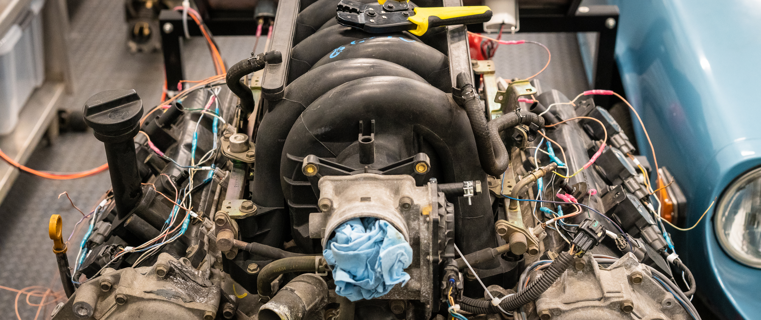
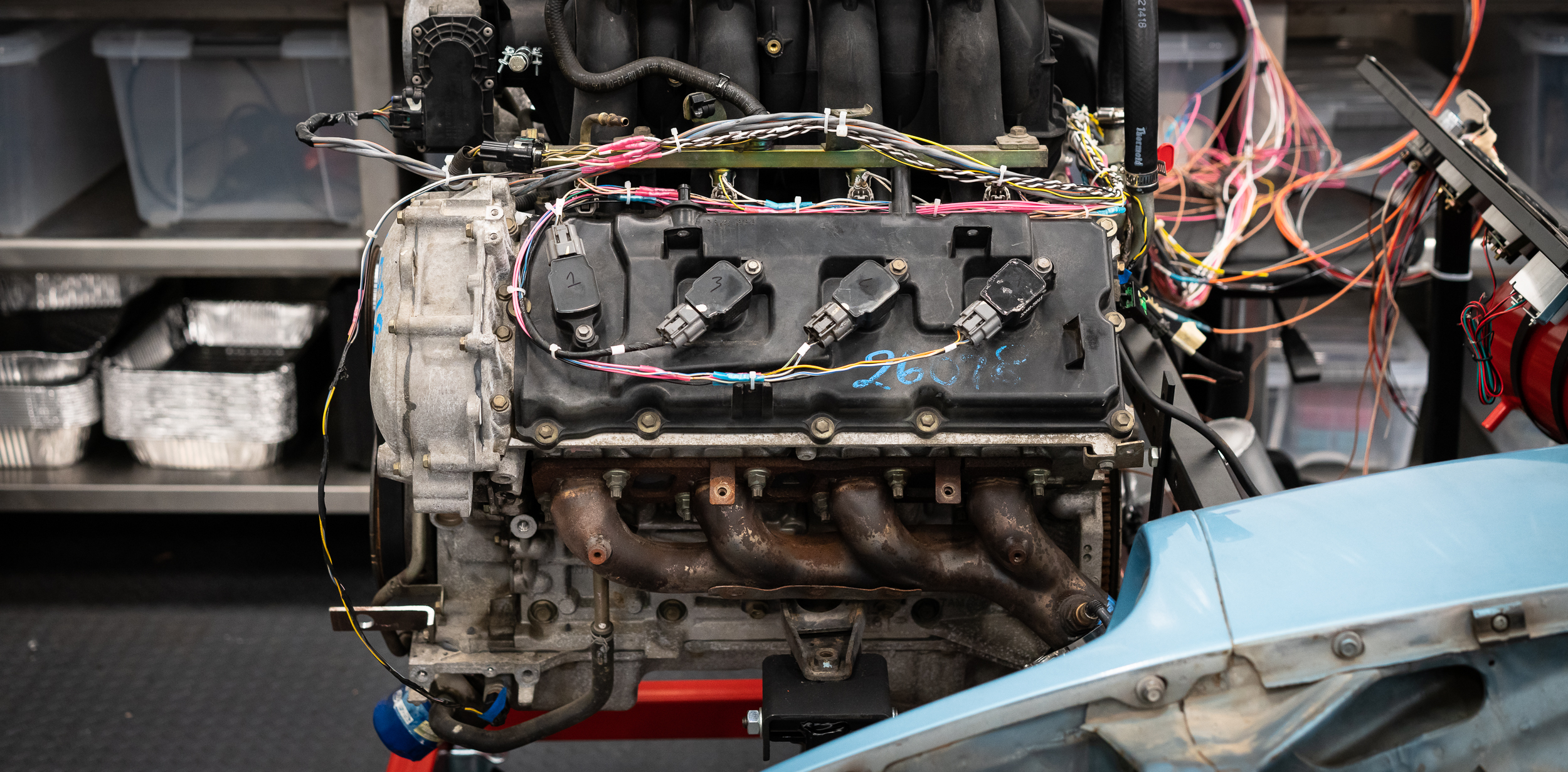
Meanwhile, the VK sits on the stand, waiting patiently.
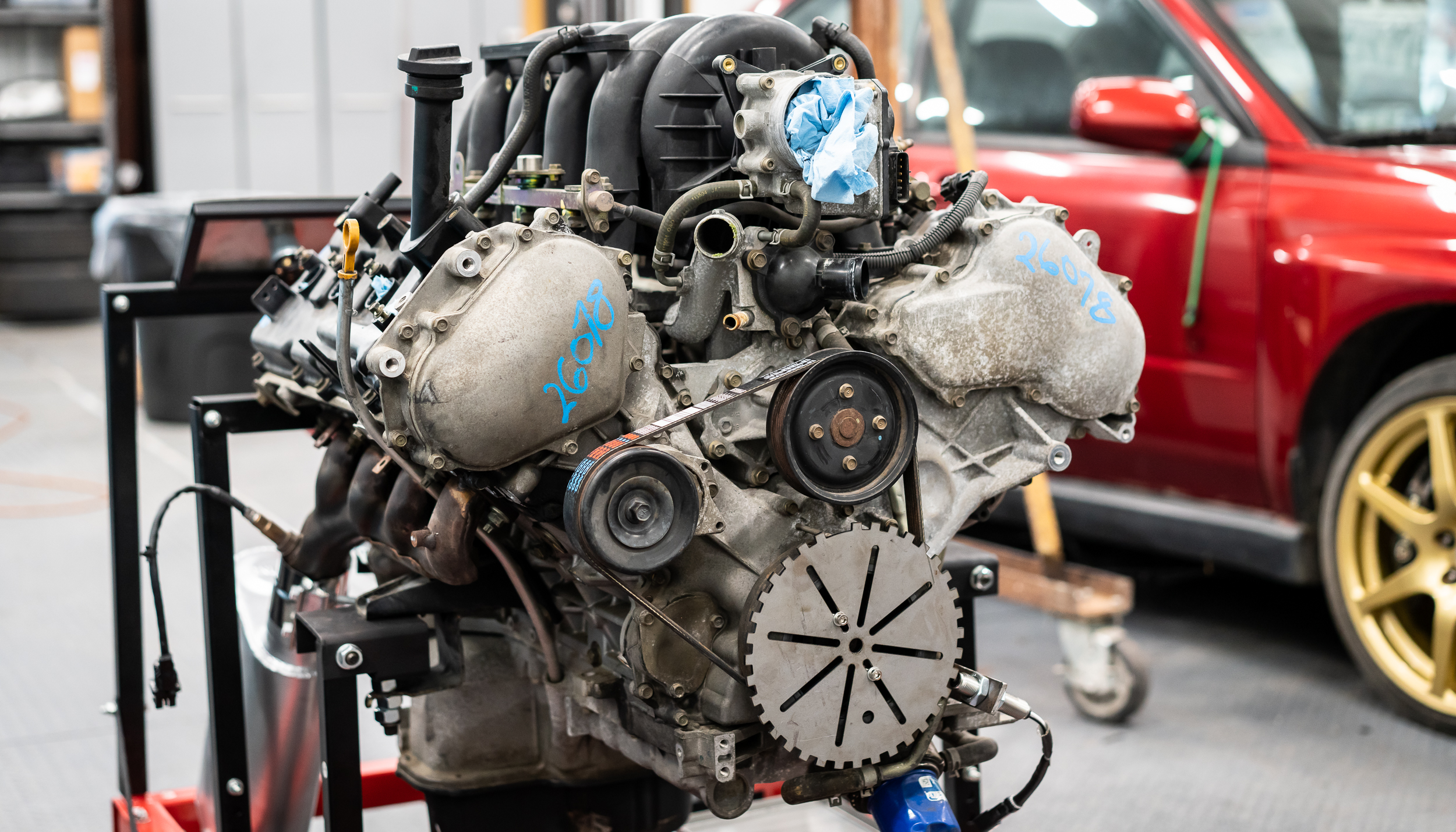
I too frequently find myself overwhelmed by this project, where even "just do something, anything" doesn't work. I walk around in circles with a tape measure, trying to get my bearings. I'm at the point of wiring this thing up on the stand, but I was having a hard time even starting that: how long do I make the wires? Should I try to mock it up so it can work in the car for initial install (I think yes), but then where will the ECU go? Hell, where will the firewall even be? You get the picture.
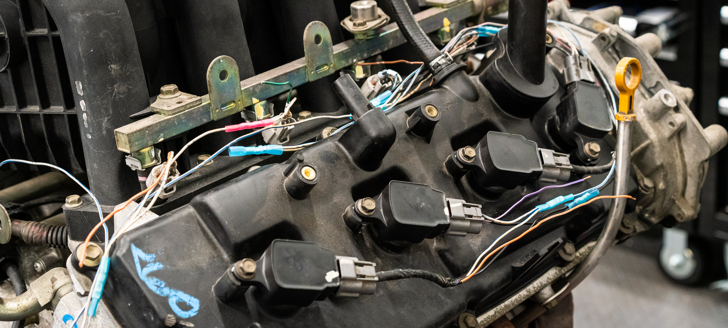
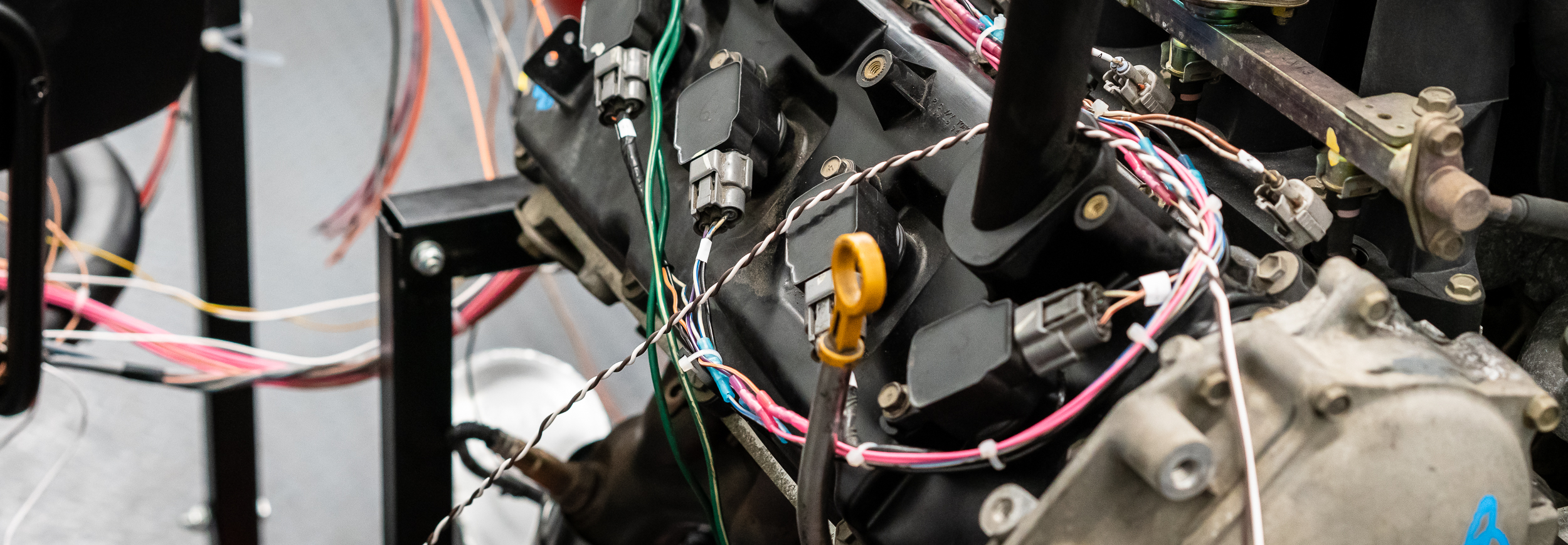
I started by just putting in the spark plugs and ignition coils. Just. Do. SOMETHING.
Random aside- the banged up oil pan extension seems to be leaking.

I'm going to try to flex seal tape over it while it sits on the stand. That piece has to be replaced for ground clearance anyhow.
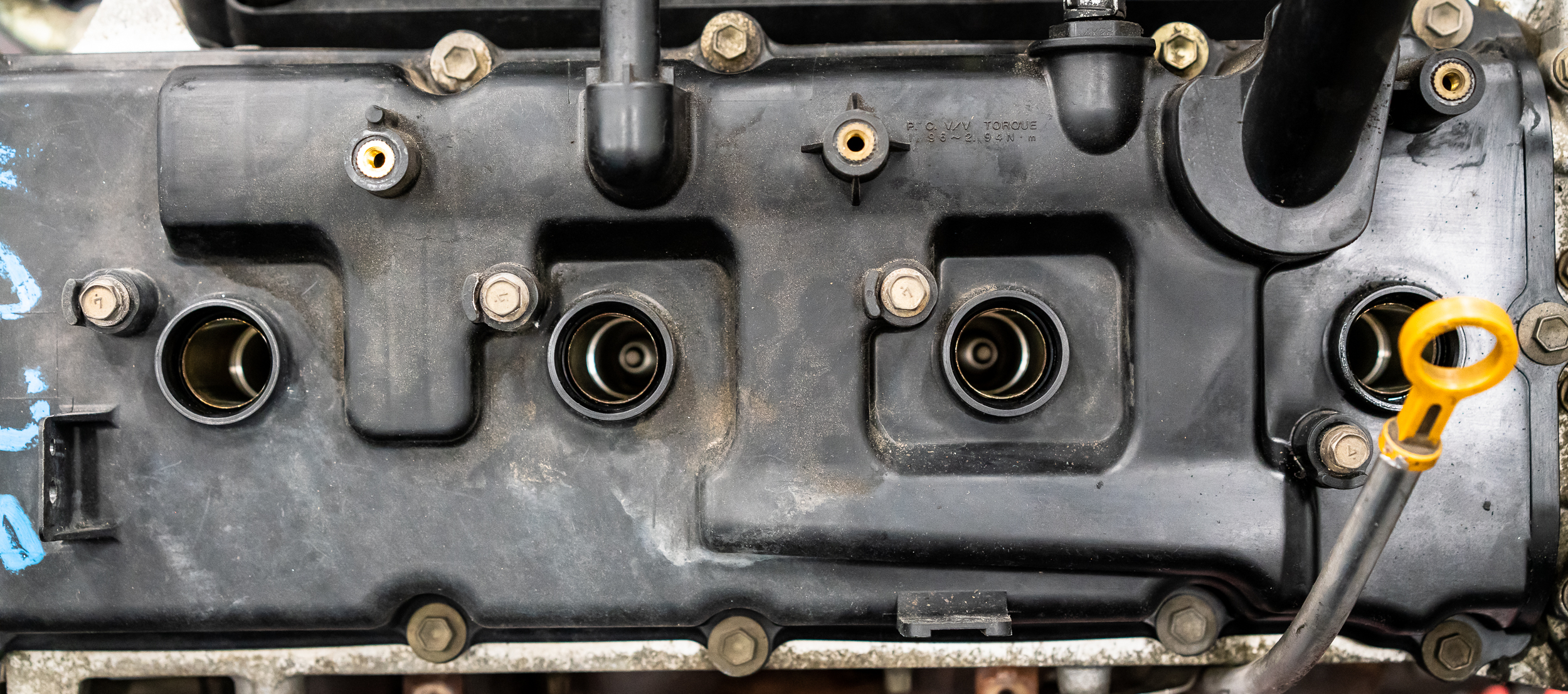
Nothing tricky here with the engine on a stand. Spark plugs, pre-gapped to 0.043".

Nothing fancy needed to idle on the stand.
The pro racers use a dab of coppa slip as an anti-seize for the plugs. I didn't have any, so just a grain-of-sand-touch of the high temp stuff, since that's what I had on hand. The nickel anti-seize is designed for the crazy hot stuff. I bought this for wideband sensor installation. These spark plugs will be in the car for exactly 0 driving miles, so this really wasn't necessary at all.

Done.
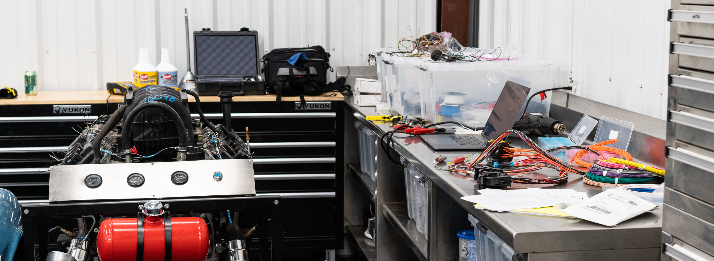
At this point I loitered around, waffling about how to attack the wiring. For an hour and a half. All I managed to achieve in that time was cleaning the table at which I'd be working.

I do love this table though.
I wheeled the engine over. It moves really nicely on the test stand.
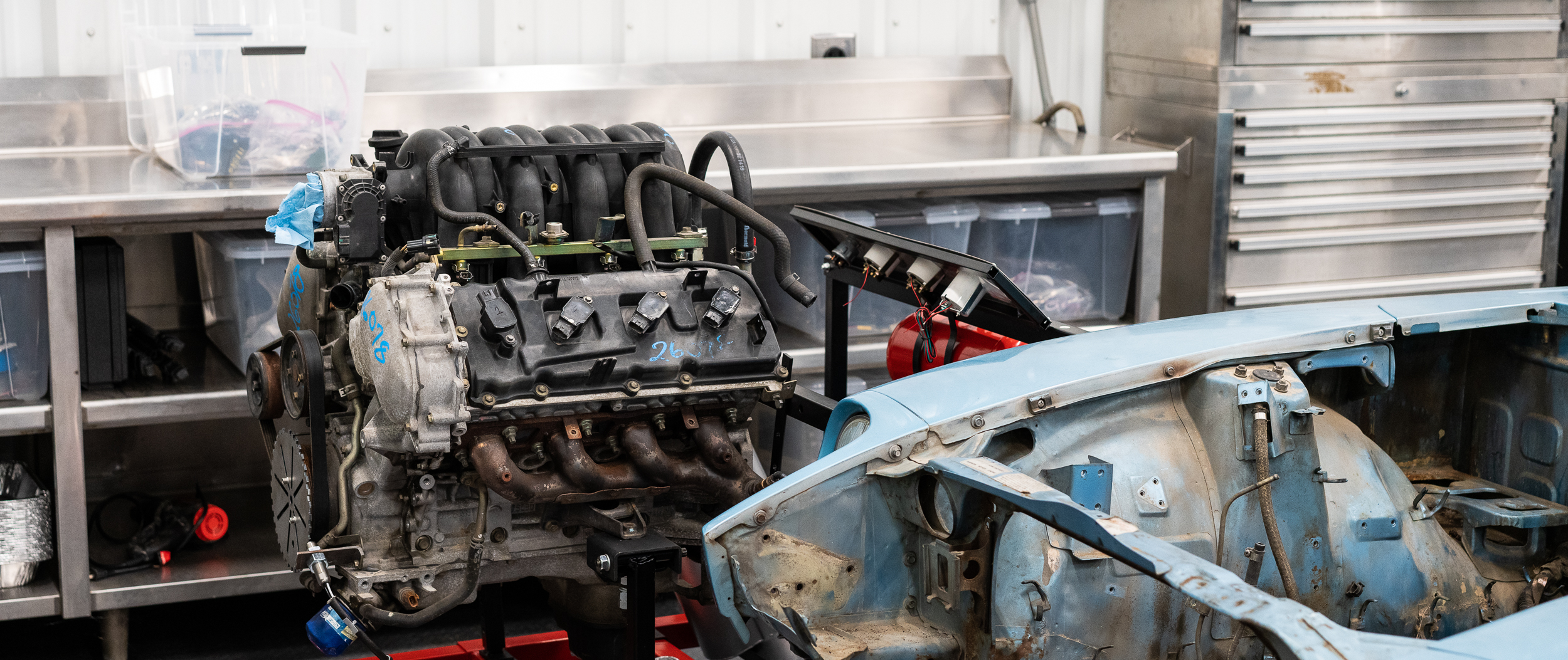
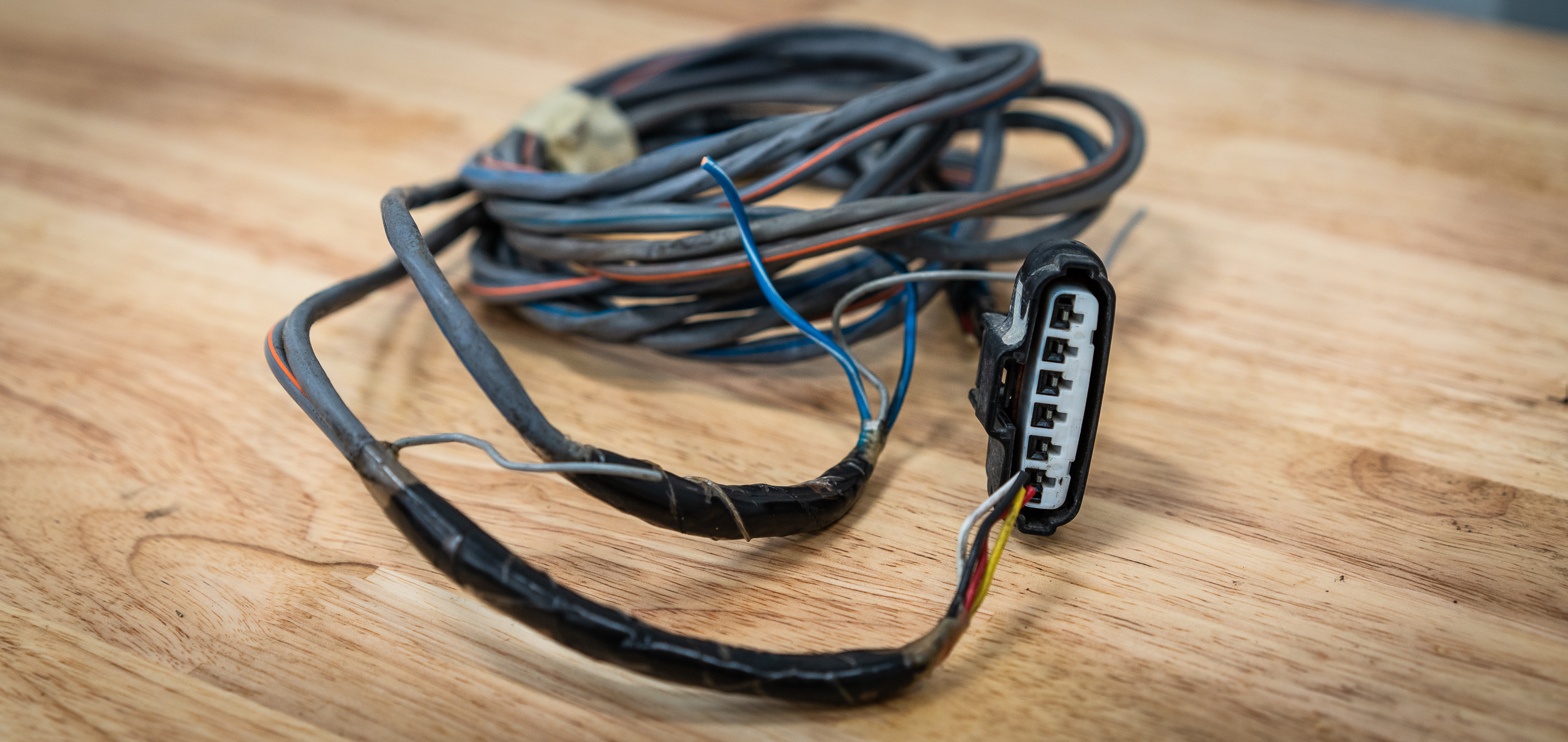
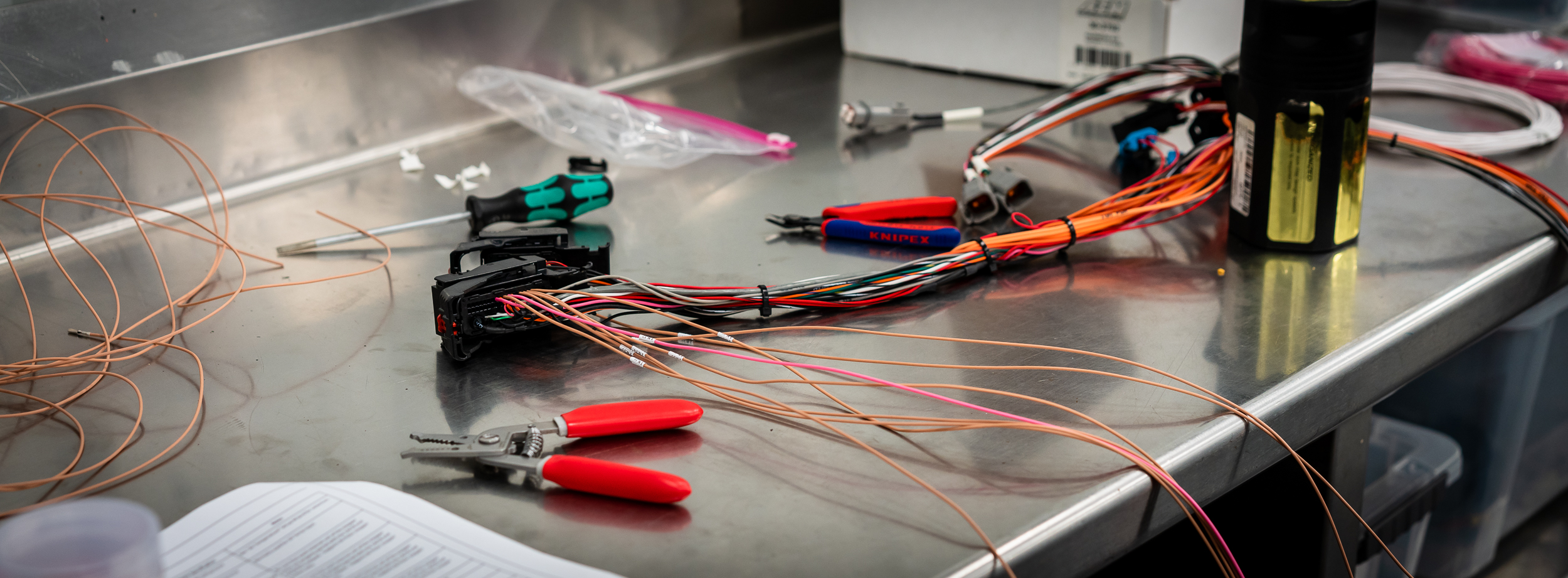
Then I pulled out all the boxes of wiring, ECU's, starter harness, and connectors to get an idea of where I was going.
Many more laps later, I decided to re-use as much of the OEM wiring as I could to run to the passenger side rear of the engine. I think the ECU will go somewhere around the passenger footwell? I will definitely try to use a Deutsch Autosport connector at the firewall because reasons, so running everything in that direction seems like the way to go? Feel the confidence.
I started to get a bit panicky about how much shop time I'd wasted with my indecisiveness, but I managed to pull out the bag of injector pigtails and plug them in to the injectors.

From there, it wasn't too hard to just start running the +12V power to them. 8 is a nice number for splicing/splitting connections. The factory used 3 -> 1 butt splices, but I prefer the tidiness of doing 2 -> 1 in a couple places. Very balanced.
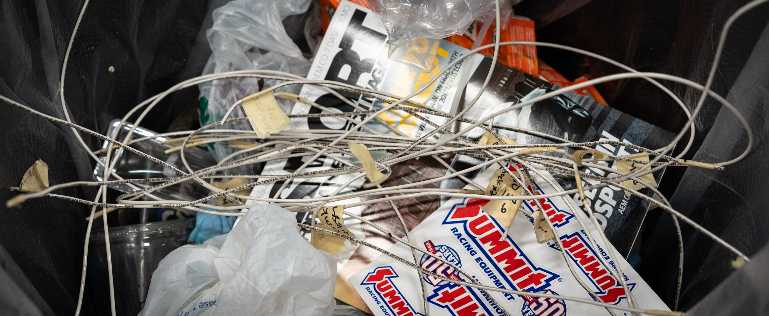
As I ran the wires, I realized that all the work I did with the house solid-core wire template was not what I wanted. In the bin it went. Live and learn I guess.
At some point the work area got pretty full and messy.
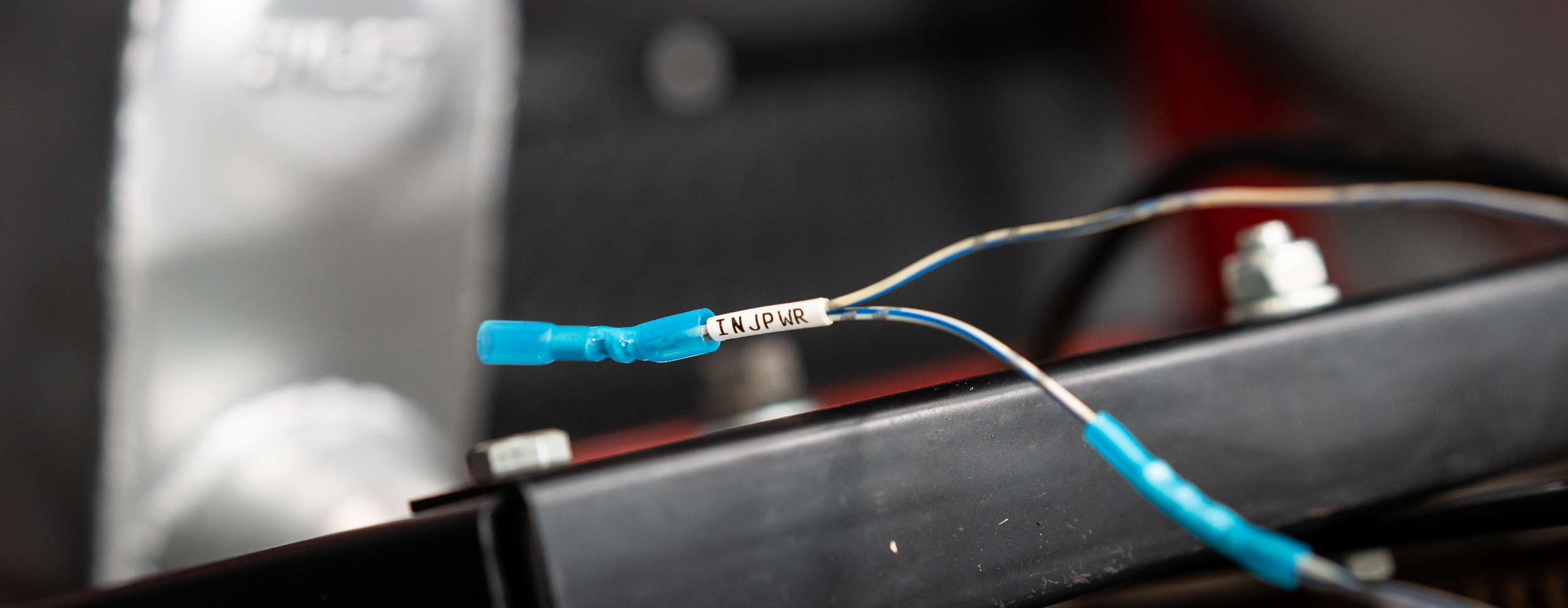
I finished up the injector power and labeled it near the final butt splice on the passenger side rear.
One thing I wish I'd done differently:
When disassembling the old OEM harness, I wish I'd totally unwrapped everything, then left the pigtail wires as long as possible. There are a couple extra splices I needed to lengthen wire that could have been totally avoided.
This wiring will be married to the AEM starter harness that I ordered with the ECU. I've done enough wiring since I ordered this that I sort of wish I hadn't. I would rather put that money towards nice wire to make my own harness from scratch. Oh well.
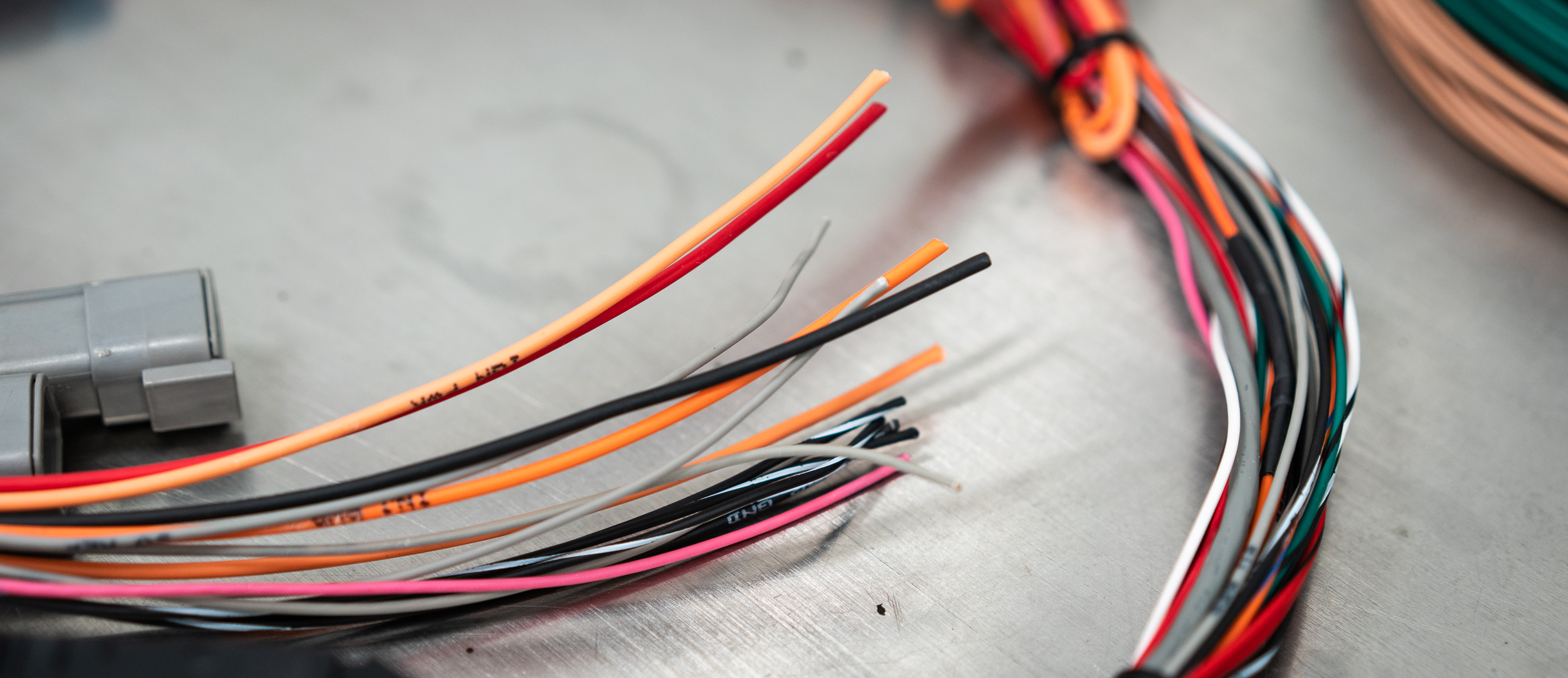
Here's the ends of the mini-harness, all nicely labeled and integrated with a small fuse box:
I moved on to the ignition coil power and ground, which I worked on until time expired. I got a decent amount of those done on the passenger side of the motor, but didn't quite make it over to the driver side.

I've found a great deal of value in totally cleaning up at the end of each shop night. It does take 20 - 30 minutes, but it helps me stay organized and do some final thinking before I leave. Frequently I'll remember things to check or realize I need to bring/buy something else for the next shop night. This night was particularly messy, but it got done and I'll have a nice fresh start the next time.

damen

"Paralysis by analysis", i.e. OMG there's so much to do, where do I start? Eventually, you just *start*. Eat that elephant, motherberkeleyer!

I start by just diving in and berkeleying something up. Get it over with and out of your system... The then required act of rolling over and berkeleying down until it is fixed, builds momentum and off you go. Getting stuff right gives you the sense of achievement that fuels every successful project.
Have I mentioned that you should work on this a lot more cause I enjoy the updates?
Pete
AngryCorvair said:"Paralysis by analysis", i.e. OMG there's so much to do, where do I start? Eventually, you just *start*. Eat that elephant, motherberkeleyer!
I reckon you're right on here. I appreciate the pep talk!
NOHOME said:I start by just diving in and berkeleying something up. Get it over with and out of your system... The then required act of rolling over and berkeleying down until it is fixed, builds momentum and off you go. Getting stuff right gives you the sense of achievement that fuels every successful project.
Have I mentioned that you should work on this a lot more cause I enjoy the updates?
Pete
Good feedback here, thanks for that. I've already gone down the wrong path a couple times (see: foam engine, solid-core wiring template) and suspect that I have many more mess-ups ahead. I can only hope they are as cheap as the two I mentioned :)
I really appreciate the nice words about the project. Although it seems everyone on the internet is doing a 240/260/280 swap right now, I'm still extremely excited about my version and I will be carving out some more time for it in the near future.
I finished the power and ground wiring for the injectors and ignition coils, at least to the back of the engine where I'll splice them into the AEM harness.
One thing that's been gnawing at me a bit is the drive-by-wire throttle body. I'm not actually going to use it (or drive-by-wire period) on the actual engine build, but I am going to use it to test on the stand. The electronic throttle body has a position sensor in it (obviously), which I will use for this first engine stand tune. I'm going to get it running on an alpha-N tune (throttle position) instead of MAP of MAF because that's what I'll use for the final build (because ITB's).

It's been gnawing at me because I've been unable to find good documentation on it, including the pinout. There are 6 pins. I think because the wires were in their own conduit in the OEM harness, I left myself with a nice long pigtail to work with at least. Yay.
I did find some people guessing at the pinout based on some throttle body swap that the Titan folks were attempting at some point. I used that as a starting point to figure out how this all worked. I'm glad I did find that, as it was correct in identifying the red wire as the TPS (throttle position sensor) ground (!?).
Nik's targeted mass acquisition syndrome has a tendency to be very useful and it worked out yet again in that he had not one, but two, variable power supplies to use for testing. I hooked one of them up to the yellow and red wires (yellow = sensor +5V, red = sensor gnd), then hooked the other up to the two motor wires (blue with stripes), and then hooked up a multimeter to the black and white wires (sensor output voltage).
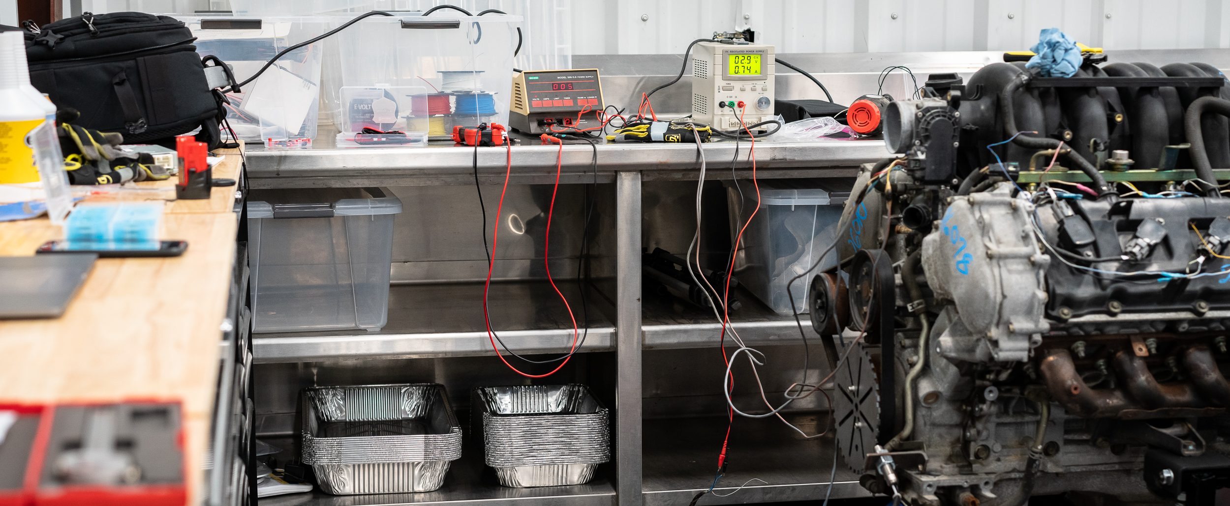
I fired everything up and got some good readings from the sensor (+3.7V with the throttle plate closed), yay. I started ramping the voltage up on the motor wires and heard a click, but no movement from the plate. Figuring I had the polarity reversed (dbw is usually driven by a half-bridge circuit that uses voltage to open, then reverses voltage to forcibly close), I switched the leads on the motor wires. Again, I got a click but no movement. I pushed the voltage up to 12 then 13 then 14, but the power supply maxes out at 3A, and I still couldn't get movement from the plate.
I thought maybe it needed a bit more current to get the throttle to open initially (then less to keep in position, or close it), so I grabbed a big Schumacher battery charger and set it to the 20A output. Fortunately, it was too smart (we suspect from not seeing a load) and did nothing.
Not to be deterred, I grabbed a spare battery and put the leads right across it. Still clicking, but no movement. At least we knew it wasn't a supply current limiting problem.
I read somewhere that you should be able to move the throttle plate by hand, so I tried pushing myself. No dice.
Only one thing to do then. Push harder.
With a moderately terrible noise, it broke free and rotated, showing a ring of corrosion that had stuck it shut. Yay! Brute force and ignorance wins again.
We hooked the variable supply back up and sure enough, it rotated open with varying force as I applied more or less voltage. There is a return spring in there as it slowly closes itself when you remove the voltage.
With that, I consider this particular issue solved for now and will move on to the next piece of wiring. I feel better.
damen
Brute Force + Ignorance FTW!

In reply to AngryCorvair :
I've always referred to this as the Caveman Method. It rarely lets me down.

AngryCorvair said:Brute Force + Ignorance FTW!
This has been my preferred method of progress on every project ever.
In my electro-mechanical / valve based electronics past we always referred to this approach as "Percussive Maintenance"

Can you share some more of your thoughts on using the DBW throttle and intake on the test stand when you're actually going to run ITBs in the car? I'm just wondering why you'd bother running the engine with that intake scheme when the VE of the engine with the ITBs will be so completely different that there's little point in building a map with one intake to only later run another.
I bet the ITB engine will start on the manifold map, but everything will be way off, especially if you're switching to an Alpha-N load with the ITBs.
As far as productivity in the shop, I too need set targets to work on while I'm there. The to-do list helps me immensely there.
Mezzanine said:Can you share some more of your thoughts on using the DBW throttle and intake on the test stand when you're actually going to run ITBs in the car? I'm just wondering why you'd bother running the engine with that intake scheme when the VE of the engine with the ITBs will be so completely different that there's little point in building a map with one intake to only later run another.
I bet the ITB engine will start on the manifold map, but everything will be way off, especially if you're switching to an Alpha-N load with the ITBs.
As far as productivity in the shop, I too need set targets to work on while I'm there. The to-do list helps me immensely there.
Your observations are very logical.
There are a few reasons why I'm not going to straight to ITB tuning.
1. I don't have the ITB's yet. I'm hoping to run something very special that doesn't actually exist right now. Dream big and all that.
2. It's not just the ITB's that will alter the VE. I'm going to be running some ridiculous cams, oversized valves with head work, high-compression pistons, and tuned long-tube headers.
3. My reasoning for running this on the test stand is to get my hands dirty with a custom wiring harness, a standalone ECU, and alpha-N tuning. I've never done any of this, unless you count some Go-tech standalone experience on a Busso V6 in an Alfa Romeo Milano 10 years ago. I don't count that.
4. A large component to this particular setup, independent of the intake scheme, is the crank/cam triggers. It's not clear that the AEM Infinity will be happy with this cam trigger (with the I, II, III, IIII markings at 90 degree intervals on the back of the cam), and I anticipate difficulties in this general area anyhow, so I will have this sorted on the stand. This will tell me what I need to do for the cams I plan to actually run.
I want to practice all this on a $1,300 junkyard motor in stock form, which I hypothesize should be very happy to start and idle if I do my part right. I don't want to practice this on a $xx,xxx motor that I hypothesize will be very difficult to tune and will not want to idle at all. I'm trying to increase my chances of success when/where I can.
Therefore, I'm hoping the value here is in the practice, not so much the product. I suspect that you are exactly right in that the manifold/DBW/stock internals map will be pretty much useless.
damen
OK, I follow you. I'd encourage you to skip the practice in this case and go straight to some online EFI training classes and wiring classes. THEN just build the thing you want. You've got limited time, so spend it on education and then get to work. That's the path I took, and it served me very well - I fully recognize it might not be for everyone though.
Advice out of the way, do it the way you need to do it. My car projects are all engineering and learning exercises more than anything else. I love to learn and execute new things.
Very cool- which classes did you take?
I definitely see the wisdom in your advice!
I signed up with High Performance Academy, and I'm very pleased with their classes. If you wait a few days, they'll probably have some big sale for the holiday, but no guarantees since they're Kiwi. I'm lifetime premium or something like that, and it's nice. I don't recall paying all that much for the privilege.
You need basic classes - the things that helped me the most are the VE calculations that I used to build my base maps. Once those were built, the actual training classes are pretty helpful.
They offer two different wiring class paths: the full on nutzo motorsport and a newer more prole wiring class that would honestly be a better fit for you and 99.8% of people out there. I didn't take any of their wiring classes - I just planned it out on my own.

I really do hate this trigger wheel. But I'm going to test with it anyway.
It's mounted with only two bolts right now because the bolt pattern in the crank pulley is 6 equally spaced holes (so 60 deg between holes), but the pie plate is 8 (45 degrees). So I'm going to drill two more holes, 180 degrees apart, in the pie plate for a total of 4 mounting bolts.
But before I marked and drilled, I wanted to get the trigger wheel as centered as possible. I measured around the outside with some dial calipers when I bolted it down, but my final check would be to spin it and check with a runout gauge. Quite inconveniently, the trigger wheel pie plate cruise ship flywheel is blocking access to the crank bolt, preventing me from turning it with a ratchet.
Either way, I'm going to have to get the starter wired up, so I figured why not now; at least I'll be able to turn the motor easily, if not very precisely.
One (neat?) feature of the test stand is a key ignition switch. Why not wire that up?

I unscrewed it from its home and put it on the bench to figure out which key positions connected which terminals on the back. I was happy that it was all quite deterministic.
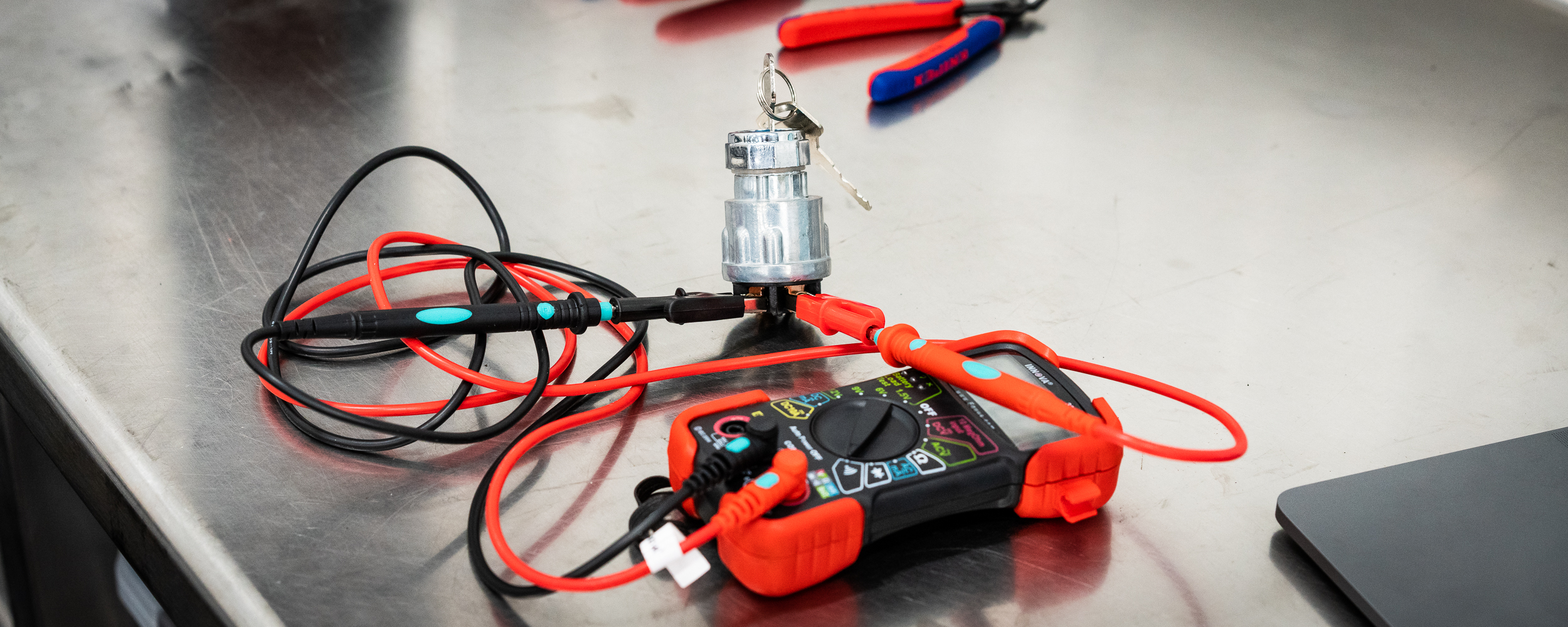
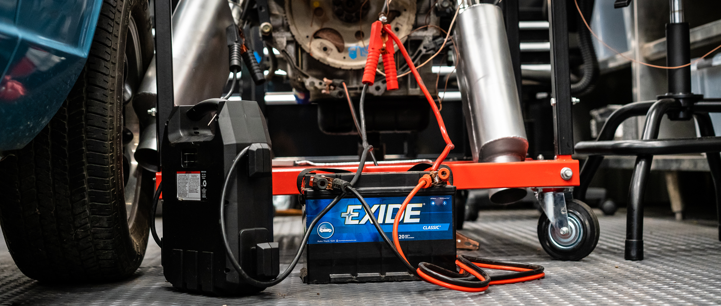
So I wired it up to the starter solenoid and hooked up some battery jumper cables to the starter to get it to spin.
Annoyingly, it seems to need a pretty healthy connection to get it to move. I would turn the key and you could hear the solenoid fire, but no spinning of the engine. I even uninstalled the trigger wheel to turn the engine over by hand to confirm it wasn't seized or anything. It wasn't.
Eventually with some different jumper cables from a jumper pack, it spun the motor just barely and then the jumper pack died. I'll order some proper battery terminals so I can ensure a good connection for next time. I wasted a lot of time on this issue.
I wandered around in circles (pensive lapping?) for a bit, trying to figure out what to do next. I randomly capped an open manifold port.

I then decided that what the hell, why not just start wiring the harness to the engine and get on with it. So I did.
Behold, the first connection of the actual ECU connector to the actual engine:

I started running the injector signals next, and it looks like I have enough colors to do each one in a different color.
Is that the right way to do it? The super professional way seems to be use all white for everything. I'm not pro enough for that, so that's out. Then I've heard of grouping all the outputs into one color, inputs another, ground and power another, etc. I'll see how I like this and adjust for next time. Either way, I'm labeling both sides of the wire.
You can see the first injector signal wire run here.

It's the light brown one with the "INJ1" label.
I printed a bunch of labels and then realized I was late and needed to leave. So here's a pile of labels.
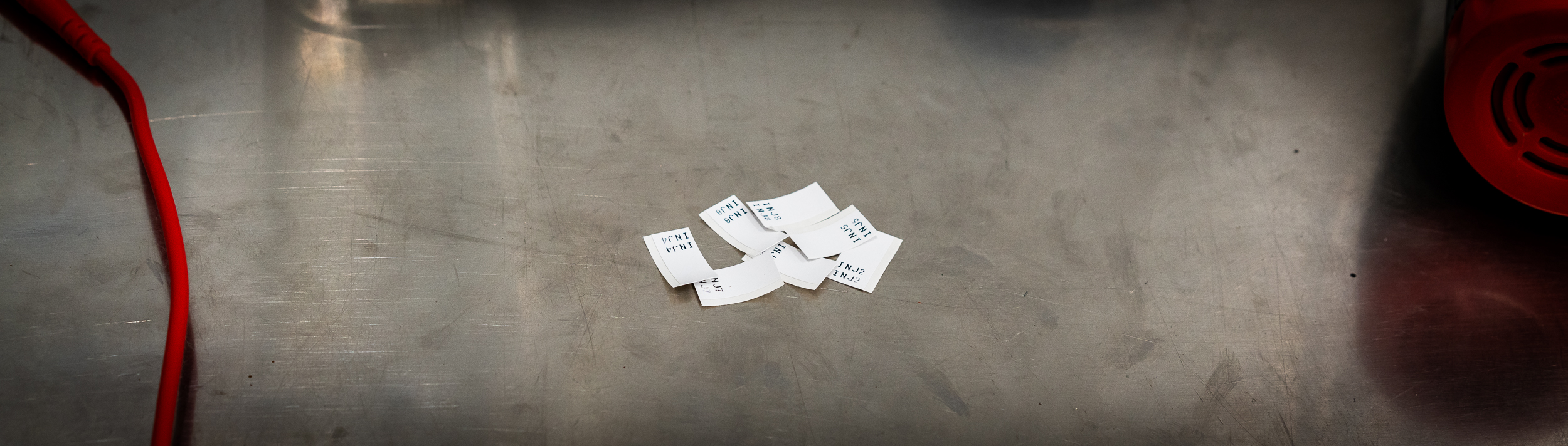
I'm not crazy impressed with this labeler. The print is not super solid (like it looks a bit faded in spots sometimes, like a printer running out of ink), and it wastes a huge amount of tape, as you can see. This everything-proof vinyl is about $0.90 / foot, which I'm not sure is expensive or cheap? I should try to mess around with different settings to see if I can waste less tape.
damen
More wiring, obviously.
I'd be lying if I said I didn't enjoy it, because I do. Peaceful, clean, orderly work.
I hope I'm doing it right.
Hooking up the signal wires to the injectors and coils.
So here's something that I messed up:

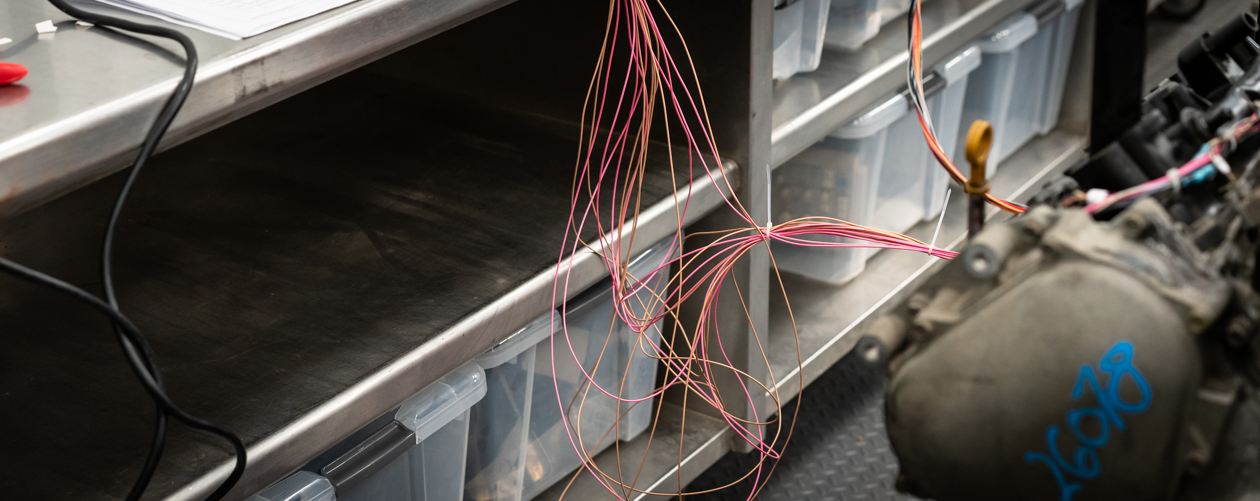
I didn't really know how long to make the harness, so I just used the full-length 8' pre-terminated wires that came with the mini-harness. Obviously, that meant I would have slack in some wires and not in others. I didn't think it would matter and I didn't think it would bother me.
Whether it "matters" or not remains to be seen, but I was wrong about the bother. It's horrible and driving me nuts. I call it my 'Spaghetti of Shame'.
Urg. I can see myself de-pinning all of these, cutting to the proper length, and crimping on a new pin. I was actually gonna start that, but the de-pinning tool needed to extract the wires from this MX123 connector is 0.025" in diameter(?!). A paper clip is too big.
And the special tool is $70.
I ordered some 0.025" drill rod from McMaster Carr for $1.75. We'll see if I can make that work, but in the meantime, it's a big ol' bowl of spaghetti for me.
Shame.
Other than that, I'm reasonably happy with how it's tidying up.

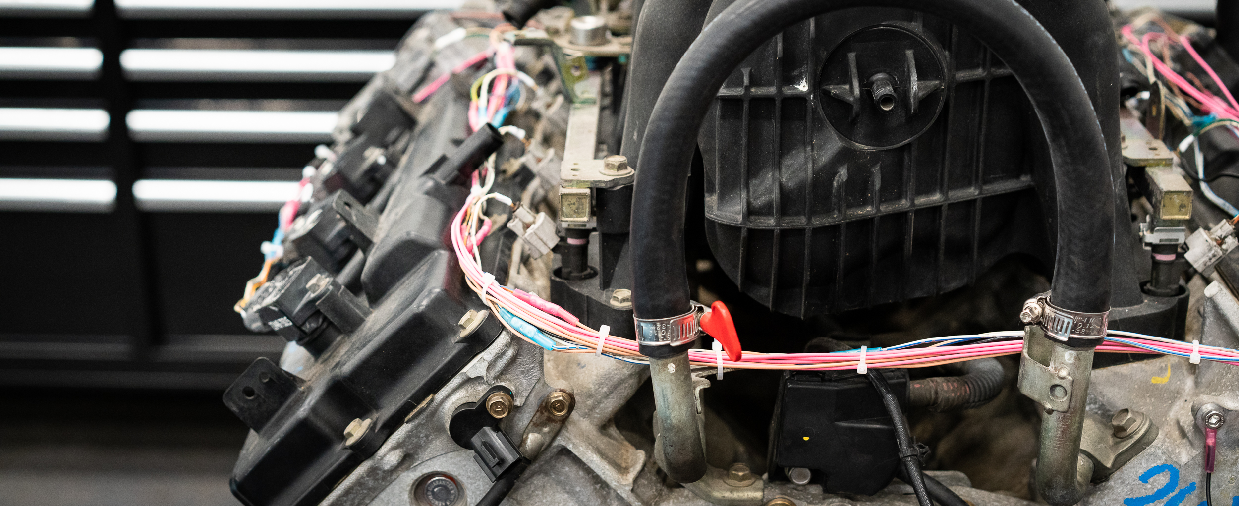
With the ignition and injector signal wires complete, I decided to wire up the throttle body next, keeping the shielded conduit in place and routing where it seemed appropriate.

As I was starting to connect the wires into the ECU connector, I realized that some of my measurements from the reverse engineering session previously made no sense. At some point I'd come up with a negative voltage for the throttle position sensor. It took some googling around and a tip from RYEphil and some more power supply work and pushing the throttle plate around to realize that the two wires from the TPS were the same signal, but inverted. So I chose the signal wire that gave ~0V when closed and ~5V when opened to hook up to the ECU. The ~5V open / ~0V closed signal wire was terminated and capped.
Hopefully that's the right choice?

Once that was sorted, it was smooth sailing to finish the throttle body wiring (DBW motor and TPS) and route it nicely.

In the bottom left there you can see the cam position sensor (which is a new part that I installed). It's 3-wire, which I take to mean a hall-effect sensor. However, the wire colors were not fully conclusive, although two twisted together with a third being thicker and separate were good hints.
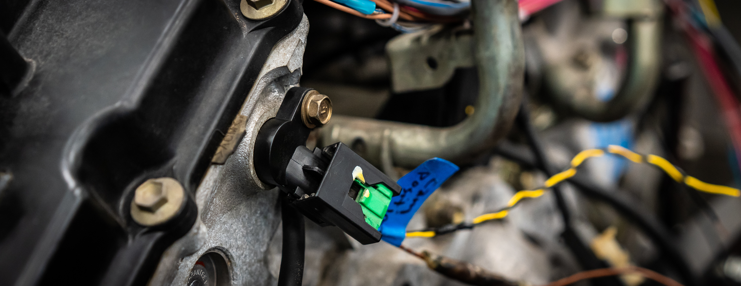
I wanted to make sure I was hooking it up properly, which means testing. Which means I finally got to use a tool I bought almost 6 years ago and has been waiting patiently in a box on the shelf!
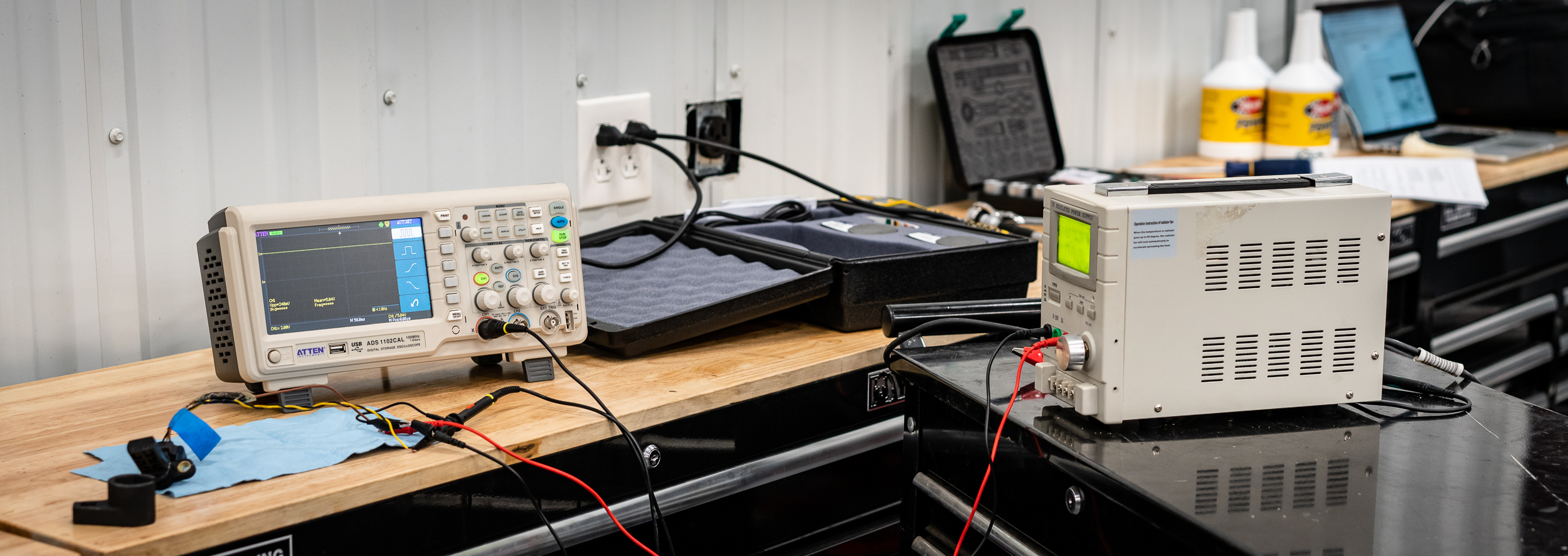
Ye Olde Oscilloscope!
With the power supply set to 5V (although I think anything from 5 - 12V should be okay), I clipped on some power and probes to the wires (black = gnd, yellow = signal, green with silver dots (?) = pwr) and pulled a random ferrous tool out of my drawer. An O2 sensor wrench in this case.
I did my best to wave the tool around really close to the sensor to see if anything would come out, confirming this particular pinout.
Behold, a signal!
Literally from handwaving.
I was satisfied that this wiring was right, so I re-installed and wired it in. Yay.
I figured since I had the scope working and setup, I might test the cruise ship crank trigger sensor that I picked out of the Mouser catalog and see if it made any waves.
The crank trigger sensor is a 2-wire VR sensor, which RYEPhil tells me is better than Hall for this application because, amongst other things, Hall sensors generally don't do 9,000rpm very well. I'm not sure I'll make it quite that high, but I definitely will be over 8k and the head room sounds nice.
I clipped on the probe and recommenced hand waving.
Behold, another signal!

It's analog, obviously, and requires a bit more processing from the ECU compared to a Hall square wave, but the AEM Infinity can take either. Stay tuned to see if this works.
Next.
There's a connector that leads into the V underneath the manifold. It has 6 pins: 2 for water temp, then 2 each for the 2 knock sensors. Fortunately I labeled it nicely when I disassembled the OEM harness. The water temp was quite straight forward- one to the signal, one to the sensor ground. Easy.

The knock sensors, on the other hand, start at the connector as 2 normal 20awg wires, then are turned into a shielded single wire cable. Here's what the cross section looks like for that:

The way to splice shielded cable involves peeling back the shielding, butt splicing the inner wire, heat shrinking around the inner wire, then putting the shielding back and using a heat shrink solder sleeve over the top.
Yeah, that's gonna be a no for me, dawg.
So I clipped off the shielded part and twisted some pairs by hand to see if that works. There's a 99.9999% chance this won't be used for this idle-on-a-stand test, but I wired it up anyway. For completeness or something.

I've been dreading messing with the crank trigger wheel, mostly because I just don't like it.
But it needs to be done. Step 1 is to get it centered.

What could possibly go wrong with that?
I have this Grizzly dial indicator and it's terrible. The mount is terrible. I don't like it. I was gonna measure, turn the motor a bit, measure, etc.
I gave up on that quickly because the whole gauge setup was unstable and unrepeatable.
Next.
I finally decided to center the trigger wheel as best I could with dial calipers, then setup my camera and film the gap between the sensor and the wheel as I turned the starter. What could possibly go wrong.
Well, for starters (heh), I couldn't get the engine to turn over on the starter. Yep, same problem as previous. Bad connections? Bad wires? Bad operator?
Do not try this at home.
I got it to turn using a battery and a jumper pack in parallel, stacking the alligators and all that. It was lame and did not feel safe.
Nik came to the rescue and gave me some fancy battery terminals to borrow and I found the OEM starter cable that looks one step thicker, so I hooked those up.
Oh, and I tightened the starter bolts, which were quite loose for some reason.
Much better.
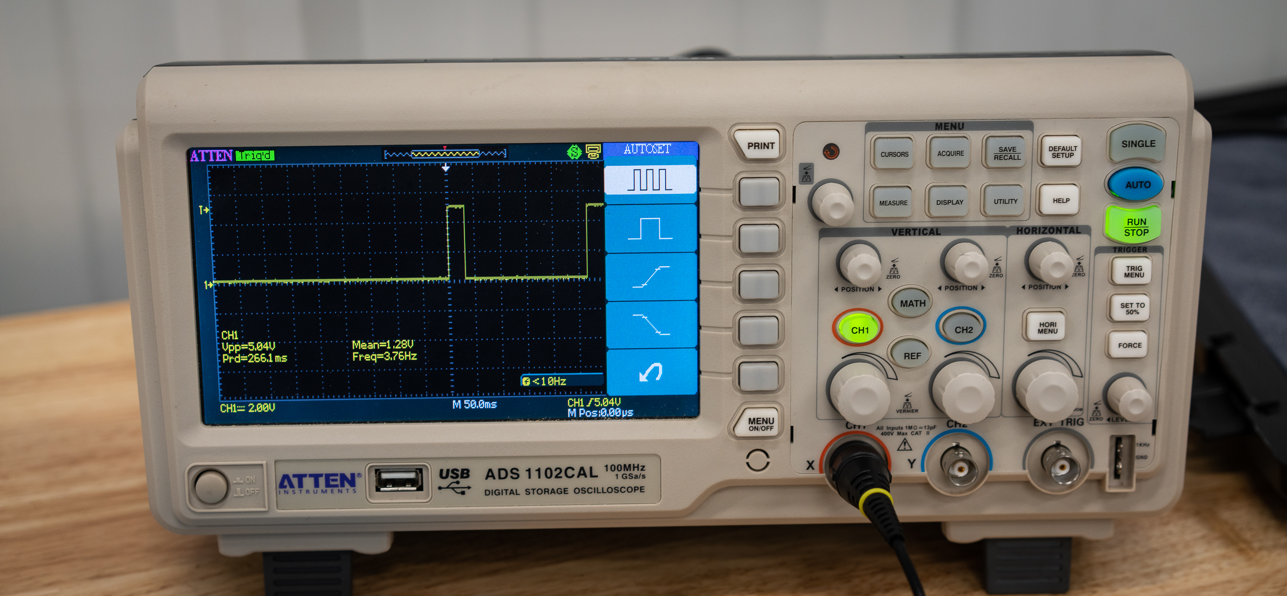
With the starter spinning nicely when I hit the key, I was able to record some video of both the trigger wheel to sensor gap, and the signal on the oscilloscope. The scope can log data somehow, but I'd need to spend time with the manual for a bit.
Anyhow, here's the gap at about 0.015".
![]()
The wheel was off center a bit, so the gap was varying between 0.010" - 0.040". However, the signal looked pretty nice! I'm pleased.
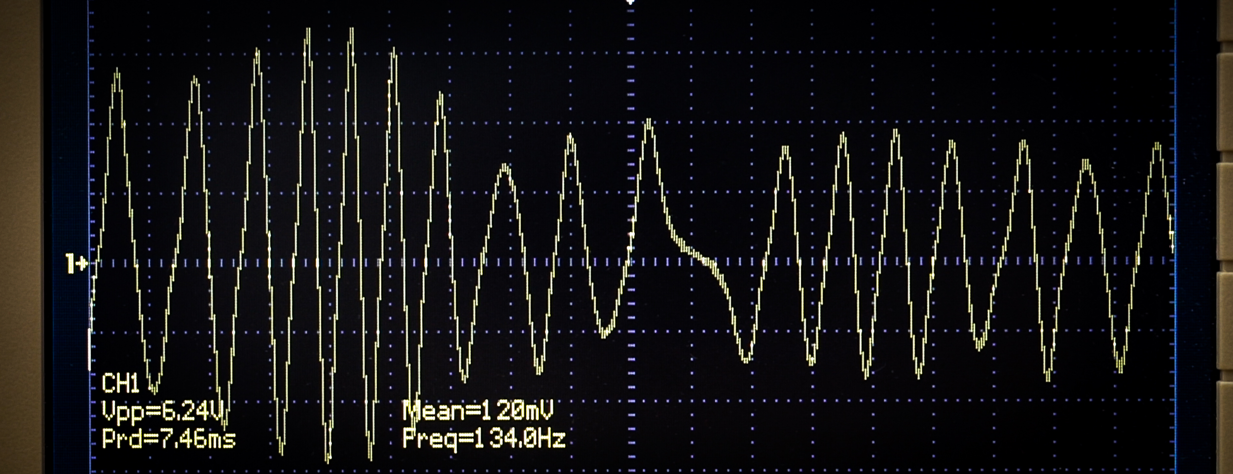
You can see the missing tooth right around the middle there; this is a 36-1 wheel.
Then you can see the amplitude of the wave change as the gap changes. Smaller gap = higher amplitude.
Anyhow, good enough for me, so I re-centered it so the variance is less than 0.010" now, and tightened it down.
Next.
damen
In reply to badwaytolive :
nice work on some daunting tasks. looking forward to more!
You'll need to log in to post.


