Hey All!
I am designing a chassis for my next project and had a question about front and rear trailing arms (VW Balljoint front and IRS rear)
At static (car on the ground in race trim) what should the angle of the front and rear trailing arms be? I was shooting for parallel to the ground, but wondered if the rears at least should be angled up or down slightly? Would this control the "loading" on the front of the chassis on acceleration?
Quick Sketch ( sorry cant get it to show ing the post correctly )
http://i565.photobucket.com/albums/ss93/sanyarcomotorsports/Buggy/chassis.jpg
Any help/opinions would be great!
Thanks!
Sean

oldtin
New Reader
7/2/09 8:31 p.m.
Not sure how wel this translates on your design, for a triangulated 4-link rear (side view) the target is to have the upper and lower links with an intersect at the center of gravity over the centerline of the front tires - providing balance between anti-squat/dive. Intersect lines above or below the CG can subtract/add squat characteristics. There's a book by Herb Adams on chassis/susp design that's good general info and the old classic sports car chassis design by Frank Costin (lotus)
If you raise the location of the rear trailing arms front mount to say 3deg up at the body the rear will plant the tires harder under acceleration then if there level.
this happens cause the rear will push forward on the links and try to push the chassis up and forward thus lifting the body some and adding dynamic rear weight.
No more the 4 deg or you might have hop on braking when the loads reverse.
Fronts are more strange as the inmaginary intersect lines also move you caster all over the place. Oh my head hurts just thing about that.
44
That looks like early Beatle suspension.
Its 72 beetle suspension used in a custom tube chassis on a dune buggy. It will be an autocross/trackday car that will see street use.
Following 44dwarfs thinking, would lowering the front pivot below center push the nose down as I accelerate from a corner?
On the super vee's, I've noticed they all run the fronts parallel to the ground and do what they can to keep them from moving (not hard considering how little they weigh)
Personally, I would do whatever is possible to ditch the trailing arm front suspension and run a more "normal" A-arm solution. Heck two sets of FWD control arms are cheap and you'd just need to build a ball joint adapter for the bug upright.

sanyarcosean wrote:
Its 72 beetle suspension used in a custom tube chassis on a dune buggy. It will be an autocross/trackday car that will see street use.
Following 44dwarfs thinking, would lowering the front pivot below center push the nose down as I accelerate from a corner?
That would be more of a rear suspension anti squat function. On acceleration, the normal reation of the car is for the nose of the car to rise in reaction to the forward rotation of the rear tires, thus transferring weight to the rear. If the rear rises, this counteracts the weight transfer and that's what a lot of anti squat does. You see that in drag race cars, the back of the car will jump straight up when the throttle is opened. Problem is, the geometry that produces a lot of anti squat could interfere with other things that could lead to evil handling of a road race/AX car. I understand what 44's talking about, but I am not sure the effort to raise the torque tube up to achieve the 3 degree up angle would be worthwhile.
To see what I mean, imagine your chassis level at ride height. The trailing arm points forward from the center of the rear wheel. If you angle the rear arm down 3 degrees with its forward mounting still in the same spot, the rear of the car has now risen. The only way to get the ride height level again is either 1) raise the front pivot point which means fabricating mounts to raise the torque tube 2) run shorter rear tires 3) lower the rear arms back where they are (level, generally).
On the front, you can do geometry to add anti dive unless, as in your case, you have trailing arms. Methinks you are stuck unless you want to get into a lot of fabrication; my suggestion is to run all the control arms parallel to the ground at ride height, get adjustable shocks and dial in a lot of rebound on the front to help control the rise.
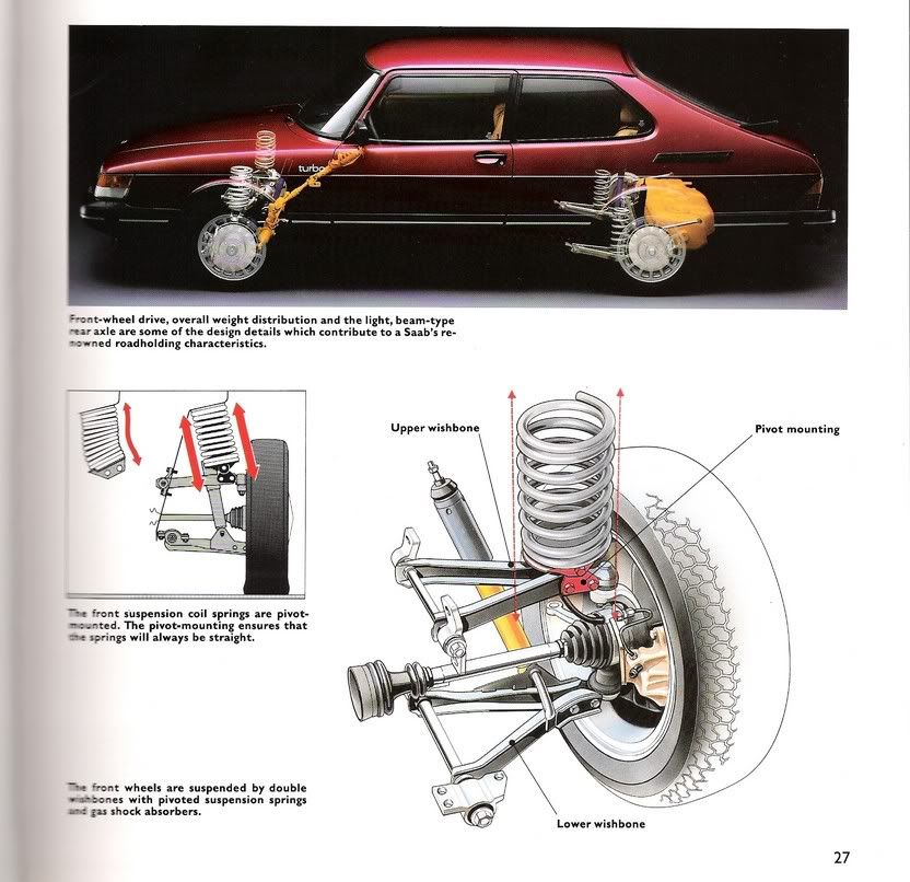
Riffing on fiat22turbo's suggestion that you look into something other than the VW stuff: you can get a double A-arm set-up from a 79-93 Saab 900 at the pull-a-part (it's got rear-steer spindles, btw). This design is set up from the factory to deal with anti-dive geometry but you could easily muck with it more if you wanted by shimming the mounting points. And caster/camber adjustments are a piece of cake (shims), though not as easy as slotted strut towers.
You'll need to engineer the spring/shocks but Davesport in WA State did this with an old VW Beetle rally car (http://www.davesport.com) and I bet you could call and get details.
If you really wanted to go nuts without spending $$$, you could put a Saab double wishbone suspension in the rear, too...
The Dodge Stratus had double a-arms and so did some of the later Honda's The trick is that you have to deal with the axle-less uprights, they usually don't take well to not having axles mounted in the bearings.
If I were to do an "A" arm conversion on the chassis the answer would probably be Miata. Lots around, and the whole shabang unbolts as a unit.

erohslc
New Reader
7/3/09 10:43 p.m.
In reply to fiat22turbo:
Just use the outer stubs from the CV axle, without the rest of axle itself. Maybe even machine off the tulip cup.
Carter
sanyarcosean wrote:
If I were to do an "A" arm conversion on the chassis the answer would probably be Miata. Lots around, and the whole shabang unbolts as a unit.
Having used these on projects in the past, yes they are very nicely made. The downside: for a car like you are building the shrouds would add a tremendous amount of weight. Were it me doing this, I'd use the Miata knuckles and both the front/rear stock upper control arms and then fabricate tubing lower arms front and rear. Narrow a Miata or Triumph Spitfire steering rack (you want the inner tie rod balls to be the same distance apart as the lower inner control arm bolts) and you are home free.
The outer tie rods for a Miata are 12mm fine thread. It just so happens the thread pitch matches a 1/2-20. So if you run a 1/2-20 bottoming tap into the Miata tie rod end, it will now fit the Spitfire inner tie rods. 
Little something I learned: Ford Taurus ball joints (MOOG P/N K8687) fit Miata front knuckle lower holes perfectly. They are a press fit in the control arm, you can use 1.750 x .120 wall tubing to make the outer ball joint mount. Or you can fab up control arm tips that use the stock Miata bolt in ball joint. I think 2x3x .125 wall rectangular tubing is a very close fit. You might need to verify that.
On the rear knuckles, if the 12mm holes for the lower pivot points are bored to .500, Energy Suspension has all kinds of urethane bushings that will work. You can also use rod ends. It's a lot easier and cheaper to do that than to try to source expensive 12mm rod ends or 12mm ID sleeves for urethane bushings.


