


https://www.rockwestcomposites.com/round-tubing/round-carbon-fiber-tubing/torsion-carbon-tubing
it appears that Cf tubes designed for torsional strength and torque transfer are much more expensive than the ones you were looking at.

https://www.rockwestcomposites.com/round-tubing/round-carbon-fiber-tubing/torsion-carbon-tubing
it appears that Cf tubes designed for torsional strength and torque transfer are much more expensive than the ones you were looking at.

In reply to Patrick :
Still not terribly expensive.
The description of the wrap patterns is interesting. The ones I looked at were all on a 45 degree bias. I remember from my cycling days that 37 degrées was a magic number because that was where the interior volume was maximized for a given strand length. (if the angle was not 37, adding air pressure would cause it to either grow in length or diameter) Wondering now how that would translate to tosional strength or if it is not particularly relevant.
The images of the products do look much closer to the aftermarket CF driveshafts I have seen. OEM shafts have a thick layer of rubber/plastic to protect from damage. The shafts aren't all that much lighter than an aluminum or even steel shaft since the majority of the weight is in the U joints and yokes.
The ones linked above are made with the same process QA1 uses for their cf driveshafts. Driveshaft work is usually the only thing i farm out on a challenge build because I don’t want to die

It's threads like this that makes me wonder if anyone has made a Locost space frame from CF.... Or more pertinent to this board- a replacement frame for a Europa- similar to the metal space frame that Dr Hess posted many years ago. Especially considering the heat issues, a Europa frame would be really interesting.

I race bicycles, a wrap of 37 degrees is because we use bias ply tyres, even my tubbis are basically bias ply tires, cannot compare with carbon lay up. My pinarello dogma lay up on the carbon is many different directions,as it needs to get the stiffness,and the compliance for ride quality, the head tube and bb have many different layers for strength and stiffness. So saying 37 degrees is magical number, is a bit strange. My bike, pinarello dogma 65.1, full campagnolo, as is should be.

Tryed,but cannot link the felt, cannondale videos on carbon bike layup videos

If you're looking to scavenge from an rx8, I'm pretty sure that all of the manual transmission cars got CF driveshafts, but steel in the auto if I recall correctly. I wonder if that was for the reasons Keith found?

In reply to Robbie :
I'll try to double check the measurement tomorrow on the RX-8 driveshaft.

When they don’t work. The burned part is where it landed on the exhaust. This did not get a shock load, just strong acceleration on smooth pavement.


Sounds like a teammate scored a 350z driveshaft for $25 today!

Not exactly on topic but hopefully helpful. Multiple years of Ford F150 have used carbon drive shafts since the 90's. Once of our Blue Oval team can provide more color on the subject. A friend had his stolen back in the day and was amazed what the replacement cost.
Wrapped carbon fiber on a aluminum core, I sold Ford's for 5 years, they are not pure carbon fiber driveshafts.
alfadriver said:It's threads like this that makes me wonder if anyone has made a Locost space frame from CF.... Or more pertinent to this board- a replacement frame for a Europa- similar to the metal space frame that Dr Hess posted many years ago. Especially considering the heat issues, a Europa frame would be really interesting.
I was thinking this after seeing those trusses as well.
Just did some back of the napkin math. locost 'book frame' calls for about 1800 inches of tubing, so say you could get away with twenty 96" pieces.
If we assume all of that is the same tubing at 1x1 16 gauge (it's really 3 different sizes, but all similar), then in steel that works out to 133 lbs and about $300 according to this site: https://mysteelyard.com/product_info.php?cPath=42&products_id=11096&osCsid=642fe0e4bd82d69aebc13cf4f4c03aa0
If we assume we can use .75x.75 square CF tubing instead (actually the closest size since the CF is measured by inside dimensions and steel by outside), that works out to about 21 lbs and $2400.
Still a little rich for my blood - for a $2100 for a 100lb savings - but can you imagine an entire locost frame that only weights 20-30 lbs?

In FSAE we did carbon everything- including some experimentation with carbon halfshafts, as well as carbon flex disc/flexible shaft designs to create essentially a carbon fiber guibo to eliminate the CV joint (and therefore a lot of weight). Just making the shaft out of carbon wasn't much weight savings, and we couldn't come up with a joint design that was reliable enough, so we ran regular old steel axles.
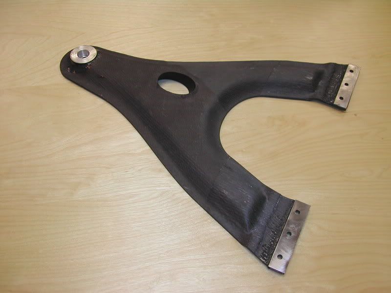
The problem with the whole carbon truss frame idea is that it's both more complicated and a less efficient use of carbon fiber than just doing a monocoque of similar dimensions- and you get tons of potential failure points at all of your junctions. For example, it's completely possible to do an A-arm using carbon tubes, but it makes more sense from a materials standpoint to make it a single piece like this:
Alfaromeoguy said:Wrapped carbon fiber on a aluminum core, I sold Ford's for 5 years, they are not pure carbon fiber driveshafts.
Ah - see we learn something new every day
¯\_(ツ)_/¯ said:In FSAE we did carbon everything- including some experimentation with carbon halfshafts, as well as carbon flex disc/flexible shaft designs to create essentially a carbon fiber guibo to eliminate the CV joint (and therefore a lot of weight). Just making the shaft out of carbon wasn't much weight savings, and we couldn't come up with a joint design that was reliable enough, so we ran regular old steel axles.
The problem with the whole carbon truss frame idea is that it's both more complicated and a less efficient use of carbon fiber than just doing a monocoque of similar dimensions- and you get tons of potential failure points at all of your junctions. For example, it's completely possible to do an A-arm using carbon tubes, but it makes more sense from a materials standpoint to make it a single piece like this:
This is also true of stamped steel vs tubular construction sometimes. The front lower control arm on a Miata is really difficult to improve upon when all you've got is a pile of tubing and a welder, for example.
How did that arm attach to the chassis? Was there a pivot of some sort, or did suspension movement come from flex of the arm? I seem to recall that F1 has gone that route.
In reply to Keith Tanner :
The titanium tabs on the inboard side were bolted to the chassis- the thin unidirectional carbon section just outboard of the tabs is the inner pivot point. It's just a few layers in that spot, you can sort of see the cross section of the flex joint if you look closely at the further portion of the arm in the photo.
That's what it looked like. Cool! Is there any long-term fatigue of the joint, or can CF just keep flexin'?

Keith Tanner said:That's what it looked like. Cool! Is there any long-term fatigue of the joint, or can CF just keep flexin'?
It keeps flexing right up until it breaks.
I had a professor doing some research work for NASA, wherein he would listen for the very first fibers in a pressure vessel to crack and then predict the failure pressure and mode of failure. Basically use the weakest link to predict ultimate failure.
In reply to Keith Tanner :
Within its' designed range, it could keep cycling way beyond the lifespan of the car it was attached to. UV exposure was probably a more significant threat to its' strength.
As Steve pointed out, though, flex it too far and you're in a lot of trouble.
stafford1500 said:Keith Tanner said:That's what it looked like. Cool! Is there any long-term fatigue of the joint, or can CF just keep flexin'?
It keeps flexing right up until it breaks.
I had a professor doing some research work for NASA, wherein he would listen for the very first fibers in a pressure vessel to crack and then predict the failure pressure and mode of failure. Basically use the weakest link to predict ultimate failure.
Sounds like reliability-centered maintenance! Listen for the failures, then you replace.
¯\_(ツ)_/¯ (if I may call you ¯\_(ツ)_/¯ ) - what sort of range of motion could you get? I want to build CF lower control arms now :)
Man, this stuff is so much more interesting than just stuffing giant dinosaur-chugging engines in small cars.
In reply to Keith Tanner :
I think we were operating with 5-6deg of movement in each direction from neutral for the flexures- FSAE at the time required 1" of bump and 1" of droop travel, and we were right around those limits. Longer arms could gain you more travel, but that was plenty for us, and the less you need the joint to flex the better.
Keith Tanner said:Sounds like reliability-centered maintenance! Listen for the failures, then you replace.
Yes, but more how to avoid reliability issues at the design end of the spectrum than the final use. For NASA, pressure vessel = rocket motor case. The first failures (3 or 4 modes/sound signatures) would provided enough info to keep from getting to catastrophic failure. The initial cracks were identified as single fibers giving up, using a set of crazy sensitive microphones bonded to the test items.
This was all 20+ years ago, so I am sure the research is public by now.
In reply to ¯\_(ツ)_/¯ :
That's good feedback about not being able to make a joint for the carbon cv axle that was reliable. What was the issue? not enough area for the epoxy to bond strongly enough? Can you describe the joint a little bit?
Interestingly, that's where my math also indicates an issue. Say we use my example from before of 3000 ftlbs being the full torque the motor could apply to the shaft. And then say 3.3x safety factor for an easy number 10,000 ft/lbs is what the shaft has to be built for. If the shaft radius is 1 inch, that means radius is .5 inches. So a joint at .5 inches needs to be able to handle 20k lbs in shear. Even with perfect 4500 psi glue, you need minimum 5 sq inches of surface area in the joint. The whole shaft may only be 8-12 inches long, so pretty quickly, your carbon fiber shaft is really just a carbon fiber sheath on a metal shaft.
In reply to Robbie :
There's the problem of bond area between the shaft and a stub going into a traditional CV joint, which is what you're looking at- and it seems like you understand the problem there. The easiest way to fix that is to increase the diameter of the shaft itself and/or get tricky with your bonded piece with holes/splines/etc to increase effective surface area.
What we were doing was trying to replace the entire CV joint as well- no bearings or anything, just a flexible stack of composite pieces. Picture a rubber guibo like on a BMW, but make it extremely thin and made from some sort of composite. Now imagine a whole stack of those, bolted together using alternating patterns to form a longer accordion like structure, and you've got basically what we were working with at each end of a CF shaft. I wish I had a picture for you. The problem was that, while they did work, it was basically impossible to get something that had the appropriate amount of angular flex and torsional stiffness without making it unstable and therefore able to vibrate in a way that caused it to self-destruct under some combination of speed/deflection/torque.
EDIT: Kind of looked like a wave spring
![]()
You'll need to log in to post.


