1 2
dean1484
dean1484 GRM+ Memberand Dork
2/6/10 7:32 p.m.

I am starting the fabrication for the mounting a TD04 15G Couple questions for the turbo gurus

  1. Does the center section have to be mounted level? If I could angel it things would be MUCH better!!! IE: does it have to be level with the pavement to the ?

  2. Is there an up?

  3. Can the oil and water flow through either direction of the center section?

  4. Has anyone made a bracket for relocating the wast gate diagram? If so I would be really interested in photos.

That is it for now I am sure I will have more as this progresses. I am in the process of laying out the location of the turbo and the layout for the custom header. It is like a puzzle in 3D.

Yes PIX to come.

Monarch notes version is to take a TD04 15g from a 850 and put it on a 924s / 944. Think Callaway type set up.

m4ff3w
m4ff3w GRM+ Memberand Dork
2/6/10 7:40 p.m.

Water goes sideways, oil will have to drain via gravity, so nearly vertical is best. Maybe 20-30 degrees off vertical would be OK.

The oil feed must be on top, obviously.

I don't have pictures, but I had to move the waste gate actuator when i "clocked" my 16t to fit in the 745t.

dean1484
dean1484 GRM+ Memberand Dork
2/6/10 8:10 p.m.
m4ff3w wrote: Water goes sideways, oil will have to drain via gravity, so nearly vertical is best. Maybe 20-30 degrees off vertical would be OK. The oil feed must be on top, obviously. I don't have pictures, but I had to move the waste gate actuator when i "clocked" my 16t to fit in the 745t.

Can you flip the center section 180? Is the oil flow directional through the housing?

kb58
kb58 Reader
2/6/10 8:15 p.m.
dean1484 wrote: Can you flip the center section 180? Is the oil flow directional through the housing?

As long as oil goes in the top and drains via gravity out the bottom, you're fine. Whether water goes left or right doesn't matter.

dean1484
dean1484 GRM+ Memberand Dork
2/6/10 8:29 p.m.

Hummmmmmm ok

vazbmw
vazbmw Reader
2/6/10 8:45 p.m.

I did a bracket for a wastegate actuator years ago. What is the question about the wastgate actuator bracket? As I remember is was pretty straight forward I clocked my compressor housing 180 degrees then fab'd a bracket to reinstall the wastegate actuator Voila

I will see if I can find pix

Don't think the center section can be flipped 180. The fat oil drain has to be at the bottom to gravity feed down to the pan. Mount at the pan must be above oil level to allow the oil to enter the pan

m4ff3w
m4ff3w GRM+ Memberand Dork
2/6/10 8:45 p.m.

The oil feed is a banjo fitting the return is not.

I'd be concerned with the oil not draining properly if the banjo fitting is on the bottom.

vazbmw
vazbmw Reader
2/6/10 8:58 p.m.
vazbmw wrote: I did a bracket for a wastegate actuator years ago. What is the question about the wastgate actuator bracket? As I remember is was pretty straight forward I clocked my compressor housing 180 degrees then fab'd a bracket to reinstall the wastegate actuator Voila I will see if I can find pix Don't think the center section can be flipped 180. The fat oil drain has to be at the bottom to gravity feed down to the pan. Mount at the pan must be above oil level to allow the oil to enter the pan. Go with the original relative position of the feed and drain The turbine housing and the compressor housing can be rotated
dean1484
dean1484 GRM+ Memberand Dork
2/6/10 10:45 p.m.

Ok some PIX.

I am going to have to look closely at the center section as it looks like the banjo bolts are water on these and the oil is plate with a couple of screws. I just need to figure out if there is a top and a bottom to the center section and what it what.

dean1484
dean1484 GRM+ Memberand Dork
2/6/10 10:49 p.m.

The SOB is going to be getting the wast gate diaphragm on and in a place where it will not be damaged by heat. I am thinking of another turbo that has the BOV and the WG as separate units so I can remote mount them giving me more freedom with the mounting of the turbo. Anyone want to suggest a Garrett unit for a 2.5 at 9.5 / 1 static? The TD04 is sized perfectly for what I want it will spool fast not have huge boost and be able to keep up with the motor to red-line.

dean1484
dean1484 GRM+ Memberand Dork
2/6/10 10:50 p.m.

I am actually considdering welding the WG shut and going remote.

dean1484
dean1484 GRM+ Memberand Dork
2/6/10 10:54 p.m.

My inspiration for this adventure.

944 Callaway type set up.

vazbmw
vazbmw Reader
2/7/10 10:58 a.m.

Ya the banjo bolts should be the water The oil drain is a fat tube with a flange on it Oil just drips out and heads down to the oil pan

Double check your turbo though. There could be a variation with oil draining through banjos

vazbmw
vazbmw Reader
2/7/10 11:00 a.m.

Going remote will add to your cost

vazbmw
vazbmw Reader
2/7/10 11:07 a.m.
My memory is coming back. I aslo welded in a section of rod to extend the actuator's arm. It worked out very well The fact that the two mounting bolts on the turbo were in different planes allowed for great bracket stability, eventhrough it was a simple bracket design
Keith
Keith GRM+ Memberand SuperDork
2/7/10 11:10 a.m.

There usually is an up from what I recall - but since you can rotate the housings on the center section, there's no reason not to have the oil feed on the top. Simply clock the housings so that everything ends up in the right orientation.

Wastegate brackets are a common thing to do, but the design will depend on your wastegate actuator design and the exact clocking.

I don't think a banjo would work for a drain. You're trying to evacuate unpressurized, foamy oil. You need a straight drain that goes downhill the entire way. No level spots, no uphill.

vazbmw
vazbmw Reader
2/7/10 11:14 a.m.
dean1484 wrote: Would you consider flipping the unit 90 degrees CCW? It looks like that would free up the space needed for the actuator, plus it looks like you are going to run into a space issue with the intake into the compressor becuase of the motormount? You are building a log style manifold?
fifty
fifty Reader
2/7/10 12:30 p.m.

Man! I wish I could find my pics - I clocked my current Mitsubishi turbo (taken from a WRX - TD04G?) - I welded up a horseshoe shaped bracket and mounted it to the original wastegate bosses on the turbo's housing . I then bolted the wastegate actuator to the "horseshoe". Took a little while, but worked out cheaper than adding an external wastegate.

dean1484
dean1484 GRM+ Memberand Dork
2/7/10 2:40 p.m.

RE: Revaz Bmw

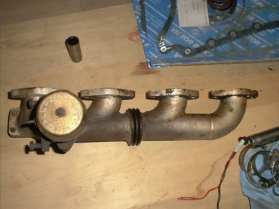
Yes I am making a log style manifold. Again I am using the Callaway one in the photo above as a starting point. I know that a true header style would be better for that last bit of performance, and who knows if I get it up and running I may try it, but for what I am building a log or hybrid log style as I like to call my elbow only design should do the trick. They are just so simple to make.

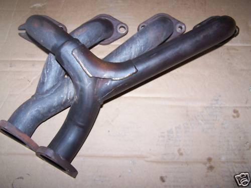
Looking closely at the Callaway design you will note that there are no T sections. It is all elbows directing the flow into the pipe. For lack of a better description I would call it a “mini header” style as opposed to a log. I guess you could call it a hybrid log style. I think that this is very important to the functionality of this style of header. Many log style headers use T sections of pipe on the middle cylinders (2 &3 in my case). Although this makes the fabrication very simple I can see where letting the exhaust out into a T would result in it going both directions in the manifold hindering flow on the cylinders up stream. This would result in alt of back pressure especially in the upper RPM’s. I also see there being a big wave bouncing back off the wall opposite where the exhaust gases are let in to the manifold resulting in some weirdness in the combustion chamber. Put this all together and my very simple minded analysis of the log header is that you should reduce many of the problems associated with log style headers by eliminating the use of T’s in the construction and instead using elbows to direct the flow into and through the header/manifold to the turbo.

Here is a better photo showing the Callaway one.

Versus the standard log with T's

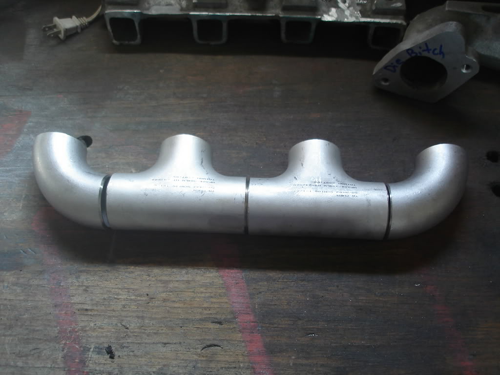
So my header is going to be made of 90 deg elbows into a strait piece of pipe. (Again the Callaway does this) I have to order the pipe, elbows and flanges. Before I did this I wanted to make sure that the turbo would actually fit in there. Since it looks like it will this will be next on the list.

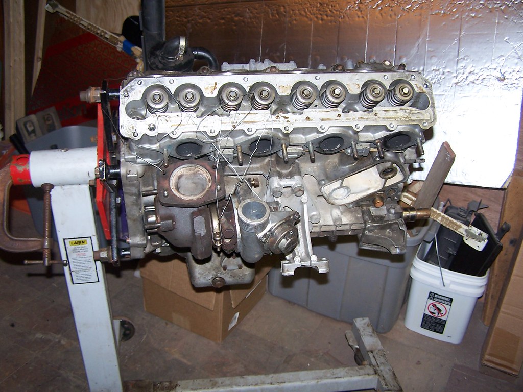
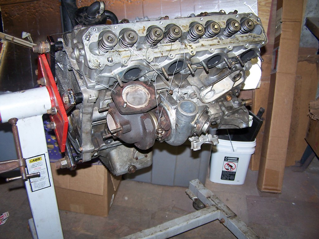
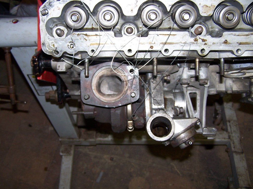
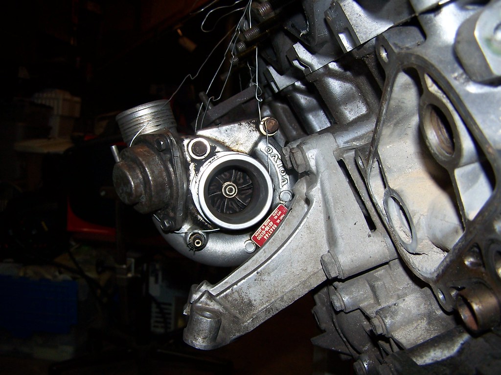
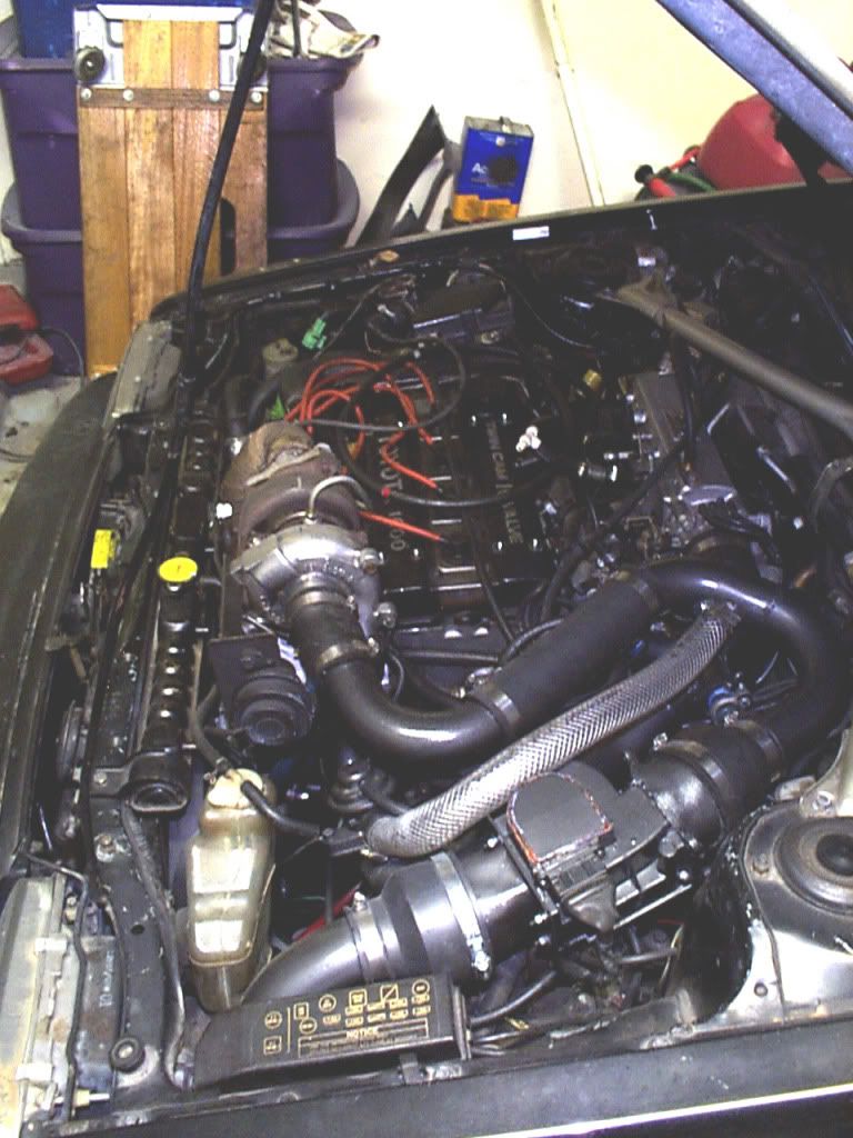
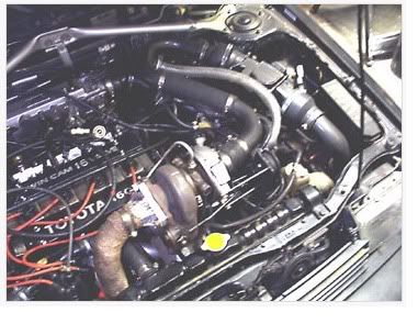
The issue is that the space between block and the sheet metal at/above the frame rail is very tight. Basically draw a vertical line ¾ inch outboard of the motor mount strut and that is all the space I have. Also there is a cam tower on top of the head that I don’t have in place at the moment. That further limits space above the turbo.

The clearance between the intake and the motor mount is actually very good. I can push the unit back another 1/2 inch.

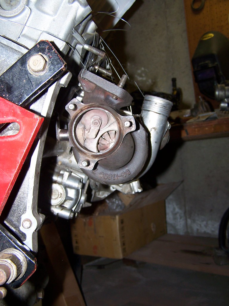
What I think I need to do is rotate the hot side housing about 30 deg clockwise kicking the waste gate lever up a little so I can push the housing back closer to the block. I also need to rotate the cool side counter clockwise so the outlet is at or just past vertical. This will / should allow it to clear the sheet metal in the engine compartment and still have enough room to get the pipe up between the manifold/cam tower. The other option is to spin the cold side so it is facing at about 7 o'clock (about 180 from where it is in the photo above) I could then just run the pipe under the motor and up on the other side in to the top mount IC (where the air box is) and then in to the intake. I am going to have to look at this. I think the best thing is to get the hot side mounted as close to the block as possible so that the WG lever works and then play with the cold side. The bad is that this will put the BOV diaphragm that is on the cold side of the turbo very close to the header and it may actually cause the turbo to be clicked out from the block some. Thinking about it putting the outlet from the turbo down and running it under the motor away from the manifold (heat rises) would be a better in terms of heat.

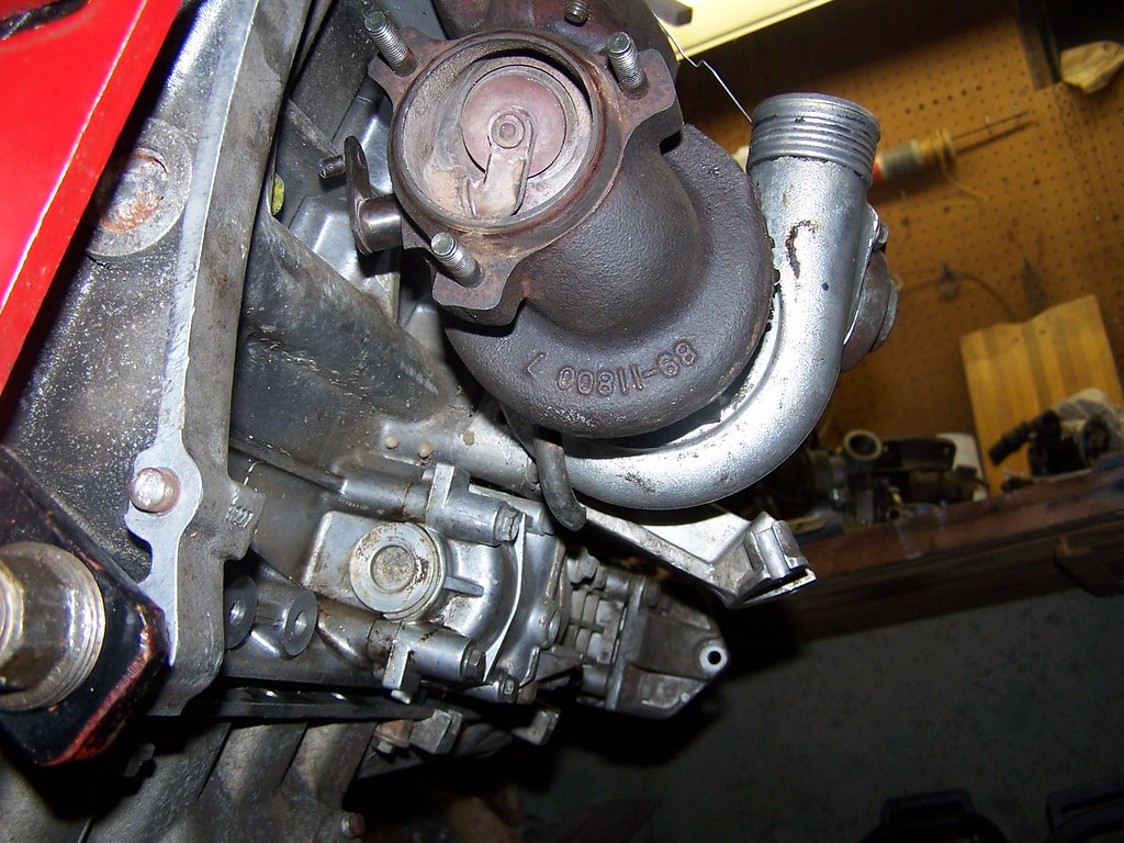
I had actually thought of flipping the whole thing 180 putting the exhaust exit facing forward. I would then have a pipe with a 180 deg bend exiting the hot side of the turbo and run the exhaust out that way. This way I could very easy plump the intake up to the area where the battery is (at the base of the windshield). This would also make running the pressurized side from the turbo under the back of the motor between the oil pan sump and the clutch housing easier. There is about a 3 inch gap there. Then again back up to a top mount IC and in to the intake on that side of the motor. The issue I have with this it puts the exhaust inlet on that side away from the block making actually fitting the turbo in place a challenge

Like I think I said it is a 3d puzzle. Change one thing to make it better and it changes something else or you run in to some other issue.

Ok time to take it apart re clock the housings again and see what we get. I think I am going to end up re clocking this about 10x before I am happy. I need to build/weld up a holder for the center section that is fixed to the engine stand. This will allow me to make these changes fast. This suspending thing with bailing wire is not the best.

Then I have to think standalone ECU for the fuel. Since I am already using a programmable EDIS based ignition system (MJLjrt from Autosport Labs) I was thinking of just going with the basic MS-I V2.3 modified to “play nice” with EDIS. I hope to make this a PIP deal by gutting a old DME I have. That way I should not have to hack up the harness keeping the experiment reversible.

More on the other stuff later. I really need to start a documentation thread on this build. Ya I know the readers rides section will be tossed at me by someone and yes I could but I like the format of a thread better. Seems to have more conducive to ideas/opinions and getting answers to things from others.

vazbmw
vazbmw Reader
2/7/10 4:24 p.m.

What is the stock manifold like? Years ago I was planning another turbo product I was going to use my stock manifold with a j-shaped pipe to the get the turbo in a similar location to yours. Have you give thought to stock manifold with a j-pipe to get the turbo into that position?

On the toyota 4age the manifold was a casted long 4into 2 headter that bolted to a 2 into one peice. So I had to make my own header.

But my 20r had a pretty simple 4 into 1 manifold. A J-pipe would have done the job really well I ran out of time an energy with kids and a growing family

dean1484
dean1484 GRM+ Memberand Dork
2/7/10 6:53 p.m.

The stock set up is a three piece Tri-Y type header. The pipes come off the manifold close to the block running down and twards the back of the motor. Right through where my the turbo is located. If I can get a set cheep enough I would use them for the flanges. They tend to crack so good ones command a bit of $$$$ and broken ones seem to get tossed.

Here is a set so you can see them. I am kicking my self as they just sold for $20 on eBay. I was watching them but got caught up watching the game Dang it!!!!

digdug18
digdug18 Reader
2/9/10 8:44 p.m.

I'd use that tri-y setup and get an adapter machined to goto the turbo. Its got to be easier then the log style manifold. I don't know if its cheaper though.

Andrew

dean1484
dean1484 GRM+ Memberand Dork
2/10/10 2:09 p.m.

I will look closer at that. The immediate problem is that it puts the turbo in the frame of the car and puts it very low relative to the pan. The turbo would end up very low making the oil return a problem. If I can get another set of those headers I can hack up I am going to see if I can cut it across the Y's and then weld some sort of collector on there and see if this would fit. Even trying this I think I will end up needing the turbo to be about 2-3 inches higher. We will see!!!!

dean1484
dean1484 GRM+ Memberand Dork
2/10/10 2:11 p.m.

This photo shows the issue of hight the best.

93gsxturbo
93gsxturbo Reader
2/10/10 6:35 p.m.

I think before I went through all that effort I would get a turbo that is slightly less paperweighty.

Even the comparable sized OEM DSM ones flow better and have more flexibility due to their design. And lots of hotter stuff would bolt up down the road.

1 2

You'll need to log in to post.

Our Preferred Partners
2irMB0qlk6xRmFCHxjrMbx0S8M0YxxSI7yrrZpXJJFrChAPNejEGOJJD5mRTQFWh