
An engine won’t last long without some sort of air supply. And for a cross-pollinated engine swap project like our Miata-powered MGB, the solution isn’t going to come from the catalog.
Until this point in the build, we’ve stayed pretty true to one self-imposed restriction: All of the parts used for this swap have come from either the Mazda or …
This content is available for GRM+ members and Grassroots Motorsports magazine subscribers only.
Read the rest of the story
Very nice project.
Although you will certainly have your hands full with important mods, if you have any time for appearance, you might give thought to making the engine look more British.
This is the upper plenum of a 3.4 GM engine after I took a belt sander to it, and had one of my MGA Twin Cam cam covers scanned 3 dimensions and then cut into the plenum with computer operated milling machine (it's in a Jamaican rebodied car so doesn't look like an MGA engine bay as much).
And thanks for the very interesting air flow study!

dennisg
New Reader
11/8/17 11:46 p.m.
great article.
I envy the short nose on your supercharger, not wanting its air intake in my driver's compartment I will probably locate the blower forward and drive it from a layshaft .
I love these articles. Because of the spoiler on the Mustang, I ended up with a magnehelic gauge. Now it looks like I'll be saving pennies for a flow bench 

JoeTR6
HalfDork
11/9/17 7:02 a.m.
The timing of this article couldn't be better for me. I spent last night staring at an intake manifold wondering how I'm going to feed it air. After reading this, a heat shield is in the works. Thanks.
The one thing I dont see in the article, is how much cfm's can this engine consume at full throttle. It seems to be a vital stat. If you can only consume 300cfm's, then I think anything over that is wasted unless you can drop the temperature. Other then that, thanks for the great summary article.
I can't wait to see the dyno runs showing any difference.
I made my own flow bench too. Like you I used a shop vac and a home made box. However I didn't go hi tech. Instead I made my own flow meter using a scaled up copy of a unisyn flow meter ( clear plastic tube and a ping pong ball).
I hooked it up to various cylinder heads that I had the flow bench numbers on to calibrate it and extrapolated numbers I didn't have. While it may not have been extremely accurate it helped me on one of my V12 engines. I got each cylinder to flow exactly the same as every other cylinder and about 35% greater than stock.
If it was me__and I wish it was; I have a great love of MGBGTs AND twinscrew compressors__I'd be trying to get an intake/filter rigged into that nice round hole at the back of the engine compartment. The one that gets fed nice cool air at the base of the windshield.
At the very least, utilize that intake, and isolate the filter from the heat in the eng. comp. I mean, you have all that room...
bigben
Reader
11/9/17 7:43 p.m.
frenchyd said:
I made my own flow bench too. Like you I used a shop vac and a home made box. However I didn't go hi tech. Instead I made my own flow meter using a scaled up copy of a unisyn flow meter ( clear plastic tube and a ping pong ball).
I hooked it up to various cylinder heads that I had the flow bench numbers on to calibrate it and extrapolated numbers I didn't have. While it may not have been extremely accurate it helped me on one of my V12 engines. I got each cylinder to flow exactly the same as every other cylinder and about 35% greater than stock.
That's what I'm talking about! I really enjoyed the article too, but $1k for the sensor and software... Not exactly diy in my book. If all you want to know is which setups flow best there are a lot of simpler and cheaper ways to compare the drop in vacuum. Let's see GRM do a follow up test with a hardware store flow bench on a $100 budget.
A further complication when trying to use flow bench numbers to make real world decisions is intake duct volume. Since any air in the ducting has to accelerate (on average, it's pulsed) as the engine accelerates, larger intake volume slows the responsiveness of the engine. Not lots, compared to a lightened flywheel for instance, but the difference in response time between the nearly four feet of factory intake ducting on a NA Mata, and that of a 12" total length system, is noticeable, at least in a naturally aspirated engine.
Then we get to deal with system resonance, which a flow bench wont help us with either.
Randy_Forbes said:
If it was me__and I wish it was; I have a great love of MGBGTs AND twinscrew compressors__I'd be trying to get an intake/filter rigged into that nice round hole at the back of the engine compartment. The one that gets fed nice cool air at the base of the windshield.
At the very least, utilize that intake, and isolate the filter from the heat in the eng. comp. I mean, you have all that room...
I agree with Randy and think this ^^^^^ is worth a serious look. Short straight run with ambient temp air being pushed in rather than sucked in. Lower weight by using less ducting which transfers less under hood heat and requires less insulation.
Additional reading on ducting intake air https://www.linkedin.com/pulse/air-ducts-down-earth-guide-motorsport-applications-willem-toet/

Thanks for all the comments...here are some responses.
wspohn: We've got a mockup valve cover in the car right now. We had the "Mazda" milled off another one and had it polished. I don't think we'll put MG logos in there, but it's a step in the direction you suggest.
pellingt: The print version of the story in the November 2017 GRM has more detail about this in a sidebar. We're figuring this engine needs about 275 CFM.
Randy_Forbes and NOT A TA: While the air from the fresh air vent will be cooler than engine bay air, it's quite a yucky route if it's directly ducted to the blower intake (not straight, many changes in shape, lots of places for air to get distracted along the way). We do plan to use it to keep the engine bay air cooler as you suggest. If we have time, we may try some sort of test on the dyno though.
classicalgas: Again the print version gets into this a bit. I agree that a flow bench doesn't simulate the pulses etc. seen in the real world. It more tells you what isn't working than what is. We'll find out more when we get on the dyno.
Unfortunately, it will likely be about six months before we go to the dyno. We've got to finish the rest of the fab work and get the car painted and reassembled in the mean time.

Carl Heideman said:
Thanks for all the comments...here are some responses.
Randy_Forbes and NOT A TA: While the air from the fresh air vent will be cooler than engine bay air, it's quite a yucky route if it's directly ducted to the blower intake (not straight, many changes in shape, lots of places for air to get distracted along the way). We do plan to use it to keep the engine bay air cooler as you suggest. If we have time, we may try some sort of test on the dyno though.
I don't think the "route" in the cowl at the windshield base would matter much in this case. The cowl area will likely become a pressurized plenum of ambient temp air when the vehicle is moving.
We did not recommend using the air from the cowl to help engine cooling and I think if the blower opening is left open to the engine bay it might actually hurt cooling while also raising underhood air pressure which could create additional lift reducing handling capabilities. If pressure increases in the engine bay it typically reduces the pressure difference in front/back of the radiator making it more difficult to cool the radiator.
A dyno test would only give you info about using a short intake tube and the ambient temp cowl air in the cowl plenum but not any possible benefits while the car is moving.
If you do use that opening to run the air intake through I'd suggest sealing around the tubing to the cowl so air in the plenum can't get to the engine compartment.
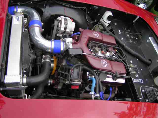
Not talking about an open filter like in the picture but with the air filter being such a restrictive thing does the route from the filter to the throttle body matter more that the route from the intake opening to the filter as I have assumed?
I played around a lot with the intake system on my super charged Grand Prix.
I ended up with a short straight shot from the filter similar to as shown above but a large volume long run to the filter "box" I made, from a high pressure area with cool outside air. I didn't do any flow testing but that got the best results in how quickly the AITs recovered when up to speed after being heat soaked in traffic. In that car it made a big difference due to how aggressively the computer pulled timing in the heat and aggressive knock retard.
Nick Comstock said:
Not talking about an open filter like in the picture but with the air filter being such a restrictive thing does the route from the filter to the throttle body matter more that the route from the intake opening to the filter as I have assumed?
I played around a lot with the intake system on my super charged Grand Prix.
I ended up with a short straight shot from the filter similar to as shown above but a large volume long run to the filter "box" I made, from a high pressure area with cool outside air. I didn't do any flow testing but that got the best results in how quickly the AITs recovered when up to speed after being heat soaked in traffic. In that car it made a big difference due to how aggressively the computer pulled timing in the heat and aggressive knock retard.
IF I'm understanding your question correctly then IMO the short answer is YES the filter to throttle body section probably matters more than the path the air follows in an appropriately sized duct from a high pressure area to the filter. This would be in most situations and of course there's always exceptions that might be caused by various unusual factors. Your Grand Prix experiment backs this up with a large duct bringing ambient temp air from a high pressure area to the filter and then just a short run to the throttle body.
That is why I'd recommend using the cowl plenum area for the filter (even if it requires it's own box to keep it from getting wet) with a short insulated duct to your throttle body and the remaining blower hole area of the fire wall sealed to your intake tube.
Your question reminded me of the 4th gen Trans Ams with "Ram Air". Owners who removed a corrugated rubber flex coupling between the air filter box and engine intake got a small power increase (with repeatable results on dynos) by switching to a smooth rubber coupling from Home Depot plumbing section costing only a couple bucks. There's a very short straight path from the air filter box to the engine on those cars and apparently just the switch to a smooth coupling made a difference.
I would think that the reason the 180° bend with 12" runner flowed better than the one without was simply due to some amount of error, since the difference was only 1.8%. BUT, if there is an actual measurable difference not related to any error (meaning the 12" runner did actually flow better than without in this setup), then it is probably due to turbulence caused by air passing through the filter, then going directly into a 180° bend. The 12" runner allowed an area for the air flow to become more laminar and therefore went into the 180° bend in a more uniform manner.
With the 12" runner the airflow had time to setup for the hairpin, nail the braking zone with the car pointed straight ahead (no tail-wagging under braking here), trail off on corner entry, then feed on the throttle on corner exit and cross the checkered butterfly plate.
Without hte 12" runner the airflow was all over the place trying to slow the car, was loose on corner entry and nearly stuffed it into the wall, drifted off track on corner exit, thus spoiling the straightway speed coming across the checkered butterfly plate (albeit not by much).
It amazes me how complex this all gets when you are trying to maximize everything. every 1/2 a horsepower in a low powered car like a miata or brz is significant at the track. But having said all of that, I tend to follow the KISS principle on most of this stuff simply because simplicity makes life easier in the long run and while it isnt always optimum, simple keeps things repeatable and easily rebuildable in the face of an unfortunate event of some kind. I try to make sure the car is solid, make reasonable improvements where possible and affordable, and concentrate on improving the driver. I figure there is more to be gained improving the driver than in any little trick mod I might add to the car. Although I never overlook the cheap and easy mods that have obvious benefits. Buying a 1000 dollar plus flowbench is so far outside the budget here that its laughable. Its hopeful that I will never need such expensive hardware. God knows I have spent a bundle in the last 3 years on tools and equipment that should serve me for a long time to come. For my money, renting someones flow bench might be an option. Or build my own using hardware store items...but to drop $1k plus on a turnkey flow bench...not gonna happen here. We are still grassroots here...and always will be.
On a related note, what is the preferred material to insulate an intake pipe from heat (or a good material to use for the piping to prevent heat soak)? My E28's intake tract runs right over the exhaust headers and I can't imagine that does my IATs any favors.
The best intakes are the ones with stickers that add 20hp.
Well done, a NACA duct does not look bad. You could then build a box to move that cooler air to the filter on the supercharger.

In reply to livinon2wheels :
I agree with everything you're saying. We weren't suggesting in the story that everyone should build a flowbench. Since we had access to one (it actually was built by the Hope College FSAE Team and I'm their advisor), we thought it would be cool to test some assumptions and give the readers the results. Much like all the stories with do with dyno's--we're not expecting everyone to buy a dyno or even buy dyno time. If we can pass our lessons along, hopefully that's helpful to others.
I'm also amazed at what people will spend on parts for a little gain when seat time, driver instruction, etc. will help more. Along those lines, and to pick up on pointofdeparture's question, I've dynoed a lot of home-brew air intakes that lost power, made no power gain, or made 1-2HP. I've often seen that working on intake temps with heat shields is worth 1-4HP on low power cars very easily. For something like pointofdeparture's E28, I'd probably make a heat shield out of steel, aluminum, or stainless and put it between the headers and the intake. I'd also probably use some of that gold heat tape/foil on both the heat shield and intake.

Jaynen
UltraDork
5/26/18 7:41 a.m.
Enginemasters also did a big air filter series on the dyno. Some filters performed as good or slightly better than an open intake. Others reduced power dramatically
bigben
Reader
5/18/22 1:03 a.m.
I really enjoyed this article when it first came out, but I and several others noted that $1200 to put together a flow bench to test intake configurations is not exactly cheap for the regular hobbyist.
Well, I finally got around to putting together a how to video on an inexpensive way to test airflow. Depending on what tools you have in your garage this could easily put together for as little as $0 - $30. Check out the video here: DIY Air Flow Testing
I used a 2.0 hp shop vac for my first attempt but found that it didn't really flow enough air to simulate a high load situation so I switched to a leaf blower that provided significantly more flow. I ran a few more comparison tests that will become a follow up video but haven't got around to editing the footage.


