Maybe a pair of these?
http://www.robotshop.com/en/pololu-dc-motor-driver-3a-5v-28v-mc33926.html
Edit: Could also use a pair of these, cheaper and simpler, although they're just a tiny bit short of stall current:
http://www.robotshop.com/en/pmod-2a-h-bridge-motor-driver.html

tuna55
MegaDork
12/5/16 3:16 p.m.
Thanks for the links! They have a dual version, so I bought that.
Keep in mind that if the output of the motor controller is less than stall current, the motors could "cut out" if you're driving the robot up a steep incline.
tuna55
MegaDork
12/22/16 10:33 a.m.
I bought this:
https://www.pololu.com/product/1213
But it has lots and lots of jumper capabilities and I don't know what I am reading. Not really.
I want two motors fwd/rev with PWM independently.
Can anyone with a bit more electronics fluency guide me into what I need to be jumpering?
I think the following:
VIN goes to the positive pin on the Pi
GND goes to negative pin on the Pi
VDD ????
M1 IN 2 empty?
M1 IN 1 goes to the PWM output for Motor 1
M1 PWM D2 jumpers next door
M1 PWM D1 empty
M1 SF empty
M1 FB empty
M1 EN empty
SLEW empty
INV empty
M2 same as M1.
Thoughts?
This document has more info on how the motor driver works:
https://www.pololu.com/file/0J233/MC33926.pdf
Pins should be:
VIN goes to the positive pin on the Pi
GND goes to negative pin on the Pi
VDD This is a 3V~5V power input, in your case it can also be connected to the positive pin on the Pi.
M1 IN 2 goes to the PWM output for Motor 1 for one direction (let's say "backwards")
M1 IN 1 goes to the PWM output for Motor 1 for the other direction (let's say "forwards") - as in the motor's other pin, the one not connected to M1 IN 2
M1 PWM D2 jumpers next door (yes, to VDD)
M1 PWM D1 empty
M1 SF empty
M1 FB has to go to ground through a resistor if you're not using it, spec sheet doesn't say what kind.
M1 EN connected to a RasPi output to control motor controller power, or VDD for always-on
SLEW empty (this will lock it in slow slew mode which is acceptable)
INV empty
M2 same as M1 (except wired for motor 2 of course)
tuna55
MegaDork
12/27/16 10:15 p.m.
Help me here:
M1 IN 2 goes to the PWM output for Motor 1 for one direction (let's say "backwards")
M1 IN 1 goes to the PWM output for Motor 1 for the other direction (let's say "forwards") - as in the motor's other pin, the one not connected to M1 IN 2
What does that mean? If I understand, I only have two hardware PWM pins on the Pi.
Also, I must be swinging and missing on the programming. I need some big time help. Can you just spoonfeed me these pins and the programming just to make the motors turn back and forth? I tried some basic boilerplate programming without one of the IN #'s hooked up, and nothing came of it. I had a program that I had used to make lights blink on and off, with PWM controlling the LED brightness, but I can't make that make the motors turn, so it has to be the way I am wiring the motors.
HELP!!
M1 IN1/2 control the power to the two pins of Motor 1, making it turn in one of two different directions. You're right that you're short on PWM channels, you'll need some kind of switching setup to switch each PWM output to IN1/2.
As-is, for testing purposes you can drive each motor in one direction (connecting M1 IN 1 and M2 IN 1 to the two PWM outputs on the RasPi) or one motor in both directions (connecting M1 IN 1&2 to the two PWM outputs on the RasPi).
I don't have time to write code right now, but once everything's wired up (and assuming you choose to wire M1&2 EN to VDD) all you need to do is send PWM signals to the PWM outputs (just like the LED test, stay under 11Khz for slow slew mode though) and the motors should spin.
OK moving onto coding help, the RasPi's default PWM frequency is 200Mhz which is orders of magnitude too fast for slow slew mode on the motor driver. To change it in Python you'll have to install this python module:
https://sourceforge.net/projects/raspberry-gpio-python/?source=navbar
BTW for testing, make sure any pins on any motors you're using that aren't connected to the motor driver are connected to GND.
tuna55
MegaDork
1/19/17 9:12 p.m.
Here is what I am doing.
import RPi.GPIO as GPIO
import time
from time import sleep
pwmpinL = 18
pwmpinR = 19
dc = 10
GPIO.setmode(GPIO.BCM)
GPIO.setup(pwmpinL, GPIO.OUT)
GPIO.setup(pwmpinR, GPIO.OUT)
pwmL = GPIO.PWM(pwmpinL, 5)
pwmR = GPIO.PWM(pwmpinR, 5)
GPIO.output(pwmpinL, GPIO.LOW)
print("Here we go! Press CTRL+C to exit")
sleep(20)
GPIO.output(pwmpinL, GPIO.HIGH)
GPIO.cleanup()
tuna55
MegaDork
1/19/17 9:13 p.m.
Won't that code change the frequency, or just the duty cycle?
The code above sets the frequency to 5Hz but then doesn't send a PWM signal, it just flips from high to low (or vice-versa depending on hardware), which will flash an LED and should make the motors turn at full power at some point, if briefly, although it's not exactly the right way to do it. I modified the code to send PWM signals "properly" and added a bunch of comments here:
http://pastebin.com/wBwCvpMm
Pastebin will preserve your code's spacing (very important in Python!)
Would've posted sooner but I only just saw your reply. I'll subscribe to this thread so I won't miss any future posts.
tuna55
MegaDork
1/22/17 10:11 p.m.
I am getting nada.
I even second guessed you a bit and tried some other stuff. For one thing, it didn't like putting the frequency at zero, so I pout 1 instead. Afterwards, I figured that you meant to put the duty cycle at 0 and leave the frequency at 10KHz, so I tried that, and nothing.
I tried checking my motors with manual jumpers, and that's fine, and I made sure my batter is powering the motor controller, and that's fine.
The only thing I can think of is perhaps I am mistaken with the wiring out of the wedge. Are the pins 18 and 19 in Python GPIO the same as the physical pins 18 and 19 on the wedge?
I have read a lot about people using "wiringpi" and that makes all of the numbers wacky, but I don't think that is what is happening.
Also, real basic here, am I supposed to be using the ribbon cable or the FTDI thing? I am dumb.

tuna55 wrote:
I am getting nada.
I even second guessed you a bit and tried some other stuff. For one thing, it didn't like putting the frequency at zero, so I pout 1 instead. Afterwards, I figured that you meant to put the duty cycle at 0 and leave the frequency at 10KHz, so I tried that, and nothing.
You're right, I should've used ChangeDutyCycle there instead of ChangeFrequency. Here's the fixed code:
http://pastebin.com/cuZvCGM8
tuna55 wrote:
I tried checking my motors with manual jumpers, and that's fine, and I made sure my batter is powering the motor controller, and that's fine.
The only thing I can think of is perhaps I am mistaken with the wiring out of the wedge. Are the pins 18 and 19 in Python GPIO the same as the physical pins 18 and 19 on the wedge?
So it runs with jumpers on the input side of the motor controller? If so that's a good sign, it means the controller is wired correctly (to the motors and power at least).
Checking the pinout, you may be using the wrong pins. Remeber that BCM mode specifies a different layout. You should probably be using BCM 13 and BCM 18 (physical pins 33 & 12):
https://pinout.xyz/
tuna55 wrote:
Also, real basic here, am I supposed to be using the ribbon cable or the FTDI thing? I am dumb.
There should be no FTDI thing between the raspi and the motor controller for sure. For programming you can connect any way you like, FTDI module, SSH over wifi, you name it.
tuna55
MegaDork
1/23/17 8:10 a.m.
I'll try those changes tonight.
DO I understand correctly that the ribbon cable is an alternative to the FTDI as far as communicating with the wedge?
Is this the wedge you have here?
https://www.sparkfun.com/products/retired/12652
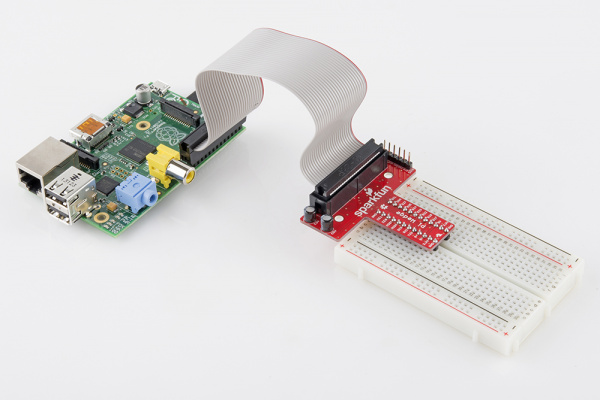
If so, you have to use the FTDI module for communicating with the wedge (on the 6-pin connector) via serial-over-USB. If the computer is old enough to have a serial port, you could wire it directly to the 6-pin connector. The RasPi should be connected to the wedge with a ribbon as seen in this pic:
tuna55
MegaDork
1/23/17 8:31 a.m.
This one:
https://www.sparkfun.com/products/13717
and a Pi 2 model B
I need to connect the Pie to the wedge with both the FTDI and the ribbon cable?
What does the FTDI do?
Thanks
The FTDI module is a USB to serial adapter device, you use it when you want to connect to something that talks serial (the wedge) with a device that only has USB ports (recent computers). The RasPi and the wedge should be connected only with the ribbon cable.
Edit: Connecting the raspi to the wedge with the FTDI cable would only give the raspi the ability to talk to itself over a serial interface.
tuna55
MegaDork
1/23/17 9:51 p.m.
I am PWMing LEDs all over, but the motors are just sitting there.
I have to be wiring something wrong.
I have tried tying both FB pins through GND to a resistor around 240 ohms.
I have tried tying the directions of either motor to the other input (so each of the two PWM pins will control both motors, and the pins will switch direction), just in case the motor controller needed them both connected.
I have tried both the 3.3V and the 5v pins from the Pi.
I would pull me hair out, but it's all already gone!
What now? Are we both missing something on how to connect the silly motor controller?
tuna55 wrote:
What now? Are we both missing something on how to connect the silly motor controller?
Must be, if LEDs are flashing from your PWM outputs it means the RasPi is doing everything correctly. I'll have to look more carefully at the pinout and see if I can find what we're missing.
tuna55
MegaDork
1/24/17 9:32 p.m.
Apparently they make a motor driver just for the Ppi, but I am not going to use it because you can't use it and the wedge, but the point here is that it may help make sense of the large number of wiring options for this:
https://www.pololu.com/product/2756
One thing I noticed is nothing they have says "empty", the things which are disabled are called "tied low", which I take to mean grounded. Do I have to ground all of the pins which I wish to leave empty?
Also they have the slew rate high, does this perhaps make a difference? I can't imagine when the frequencies we were talking about would be too low for any DC motor making a little robot whirl around.
Slew mode only makes a difference in how much noise the motors make, the motor sure won't care about the PWM frequency. I was having a look through the manual for the motor driver and saw one thing that could be wrong, do you have the charge pump capacitor hooked up to the ccp pin?
tuna55
MegaDork
4/8/17 8:54 p.m.
I think the manual you were in there is for the IC and hence the charge capacitor is in the board I bought. I don't have the CPP or VPWR pins on the board at all.
I am beginning to think this is over my head.
tuna55
MegaDork
4/8/17 8:58 p.m.
Yeah in the documentation for the board CPP is connected to the VPWR pins with a 33 nf cap.
OK, make sure anything labelled "tied low" is connected to ground.
Edit: Anything that says "tied low through cuttable trace" is already hardwired this way...but a parallel ground won't hurt, if you want to try it.
tuna55
MegaDork
4/26/17 10:43 a.m.
I am getting to the point where I am going to throw this motor controller into the toilet and buy something else.


