A question for the e-leck-trish-uns or EEs here:
I'm setting up a rotary phase converter system to power a couple 3 phase machines in my shop. I've run 10/2 Romex in conduit to a Furnas/Siemens 3 phase 230V definite purpose contactor w/ thermal protection and a 208-240V coil. The 2 hot legs in go to L1 and L2. The rotary phase converter is connected T1-T1, T2-T2, T3-L3. The power to motors goes to T1-T2-T3.
When I depress the contactor test button it starts. While it's running the 3 phase equipment runs fine.
I've bought a 2-wire run/stop switch and need to connect it - here's where I'm out of my depth. I'm good at residential + light commercial wiring, but I don't understand the schematics in the cover of the mag starter - the unit has 5 screw terminals to make control and jumper connections, 2 of which have jumpers on already.
If there's anyone here who could look a pics and make a recommendation it would be most helpful.
I'll go take some...
IIRC 3 phase is 3 hot wires that alternate out of phase with one another.
you need to run a switch for all 3 wires not just 2. If you are running 2 wires only, then you aren't running 3 phase.
Yes.
The rotary phase converter creates the 3rd leg. The RPC is wired per the manufacturer's schematic - the mag starter is fed into L1 and L2 by both legs from a single phase 240V/30A circuit - L3 is fed by T3 from the RPC. The RPC is also connected to T1 and T2.
3 phase load is connected to T1-T2-T3, and receive 3 phase power.
If what you're saying is that before the RPC starts the contactor is only receiving single phase power, you are correct. The 3rd phase (L3 in - T3 out) is fed by the RPC.
The contactor in the mag switch is activated by a solenoid that usually operates on a separate circuit.
Think of it as a relay.
The coil should be activated by 120 or 240 single phase. This engages the contacts.
You can pull 2 legs of the 3-phase supply to get 208 single phase to operate the coil. Switch this supply with your control switch. This should go to your L1 L2 connection.
This is the way we used to wire 3-phase compressor motors with a mag switch.
Shawn
Here's the rub - the contactor is fed both legs of 240 single phase into L1 and L2 - a rotary phase converter is powered from T1 and T2.
The third wire from the rotary phase converter is connected to L3. When the rotary phase converter is running it manufactures the 3rd phase.
3 phase loads are connected to T1-T2-T3,.
My confusion is the terminology on the schematic, and what to do with the jumpers. The coil of the contactor is 208/240V, and the contactor is configured "normally open aux contact 1".
Here's pics of all the components:
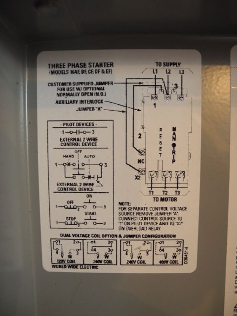
Schematic in contactor case cover.
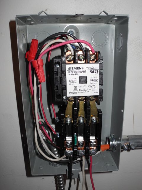
The contactor.
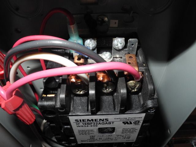
Contactor control terminals.
More:
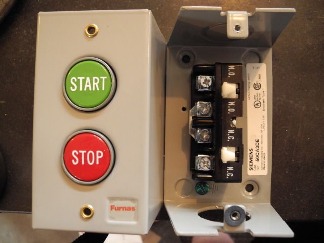
Run/stop switch.
Schematic the RPC and contactor are wired from.

To me it looks like a two leg switch basically would turn the phase converter on to provide the third leg. On the back end of the RPC there is another switch which I think kicks in with the phase converter is running which provides the third leg to your equipment. I bet it is like a solenoid/breaker type switch and when the third leg is energized it trips providing a path for the energy to your 3 phase equipment. Basically you are using your house power to run the phase converter just like a regular electric motor except it generates power for the third leg. When the phase converter is up and running and T3 is hot a switch kicks in allowing the electricity to go to your equipment. In the above diagram you need to find out where the "3 phase fused disconnect switch or magnetic starter" is or if you have it. Says it is sold separately. Sounds like the switch is a safety device, but hell if I know.
Exactly.
It's wired per the schematic above. When the test button on the contactor is depressed the RPC (rotary phase converter) starts. Hold the test button down and it continues to run. Once the RPC is running, the mill and lathe run fine.
My problem is:
"What terminals on the contactor do I connect a 2-wire run/stop switch and the jumpers, if any to"
So:
- RPC is wired correctly.
- 3 phase loads are wired correctly
There's 7 screw terminals on the contactor and thermal protection unit. What goes where?
Here is how the momentary pushbutton switch and auxiliary contact get wired up to operate the contactor. Pushing the ON button will energize the contactor, and the auxiliary contact will close to latch on the contactor. It will stay energized until the OFF button is pressed or the main power is removed.


Stuart in Minna-SOOHH-tah, that's IT!
There was a scene in an episode of "The Office" in which Michael Scott asks to be explained something "as though I'm 10 years old". 1/2 way through the very basic explanation he interrupts "No-like I'm 6 years old"...
I needed the "Reading is Fundamental" version.
Once I'd poked around w/ a volt-ohm meter, seen what was hot, discovered the normally open thing on the left simply clips on, and mechanically connects to the contact body that travels in and out when depressing the test button, and gotten brave and bridged L1 to 3 which energized the coil - your schematic made the one in the cover make sense.
I test wired and it worked, so I mounted the run/stop switch on the wall with conduit to the mag starter, did the real wiring, and installed the disconnect for the milling machine.
On which I have now made first chips. I'd have wired up the lathe but it's getting late and I need to decide whether to run conduit around the corner to the lathe disconnect or just make a longer cord.
Thanks so much for the help!
Super neat, sounds like the on/off switch must be a relay switch. You push ON and you energize the third leg for the three phase electricity. I was wondering how three phase conversion works myself.
Out of curiosity how much does a phase conversion setup cost? From what I hear you can run 3 phase machinery on single phase if you can get them started(hand start). Unfortunately running three phase machinery on single phase power only will provide around 1/2 of the stated power, maybe a bit more.
Thanks for the info on 3 phase conversion.
Nope - it's just a regular 3 phase contactor w/ a normally open auxiliary latching relay on one side. It doesn't know or care where the 3rd leg is coming from. Pushing "on" momentarily energizes the coil closing the contactor. The rotary phase converter begins to run on 240V single phase and it feeds the 3rd phase into (now closed) line side. The load side sees 3phase power, the mill and lathe make chips.
Pushing "stop" closes the normally open latching relay which releases the contact, and everything goes silent.
I'd have most likely bought a pair of variable frequency drives to run these 2 machines - they're silent, small, offer infinitely variable speed, soft start, braking, and a host of other advantages, but when I bought the assets of a small prototype shop the rotary phase converter came with. And it definitely adds a certain air of commerciality to my shop.
Cost? A 5hp RPC w/ wiring and controls can be had for under a grand. If you want to run adult sized machines it's a fine way.
Phase-A-Matic
Phoenix Phase Converters


