


In reply to AngryCorvair :
Fastest forum response ever!
Can't wait to make some more progress and share it with you guys.
In reply to AngryCorvair :
Fastest forum response ever!
Can't wait to make some more progress and share it with you guys.
Today I decided to get up off my butt and at least do a little on the rambler project.
I started by unloading my engine hoist. I re-attached the wheel mount that snapped off. Then I re-enforced the mount with a piece of flat bar on each side. One of the casters is still a little jacked up, but it's good enough for the time being. I'll replace it before I start trying to test fit the engine.

I got the engine out of the trailer and mounted on the engine stand. Then I pulled up my trusty 5 gallon bucket and stared at it. Once I'd gotten my fill, I measured some of the key dimensions to start making a game plan for how to fit it into the rambler.
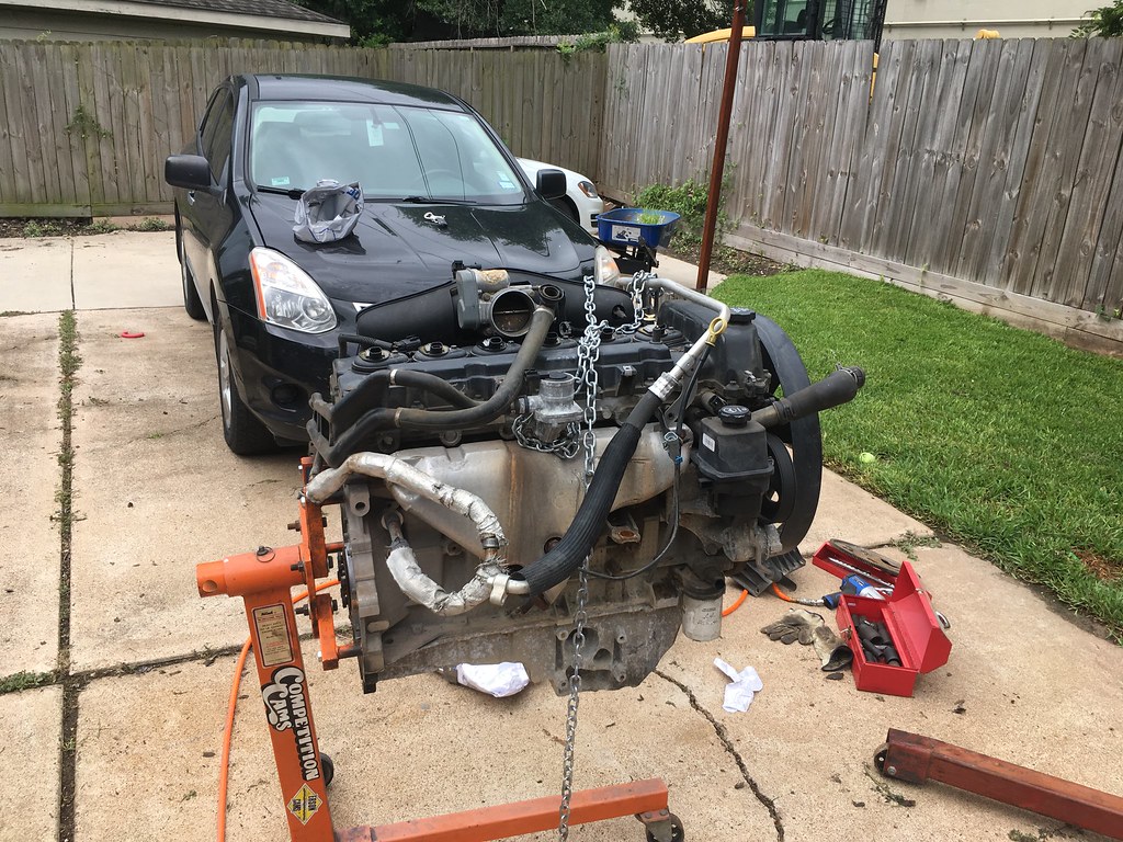

She's a beauty, but shes really tall.
From the measurements I took of the engine bay and the engine the key problem is vertical clearance. It would take a monster hood scoop to cover it without significant changes.
First up will be a new oil pan with a rear sump. There's a cast rear sump pan available, but I don't want to invest the money to buy one. I also don't really like the way the modified factory pans look. That leaves me with fabricating a pan. That should be a fun project.
I pulled the pan off for measurements and got to see the cool girdled main caps these engines have. I also poked around in the pan and didn't see any pieces of metal or debris. This engine is looking pretty good. I took an oil sample before I pulled the engine, so I'll share the results of the oil analysis when I send that off.


I started measuring the key dimensions and mounting hole positions. Now I've started modeling it. I'm having a tough time deciding if I want to plan on aluminum or steel. I can definitely do either one. The aluminum would have more cool factor but the steel would be cheaper and probably faster. Also on the aluminum I could add an O-ring groove, and do away with gaskets and silicon.
What do you guys think?

In reply to aselmike :
The first thought I have is that with a height problem and a sump problem it is time to rework the oil pickup tube and lay this thing over as far as you can to one side, then re-design the sump. Probably move top to car's right side.
In reply to TurnerX19 :
The pick up tube definitely needs to be re-worked. The engine is a front sump right now. It needs to be extended to the rear since I need a rear sump pan.
I got tired of trying to figure out my oil pan in CAD. I do a ton of CAD at work, so sometimes it's nice to just toss it aside and build.
So I used my measurements of the oil pan flange, and laid out the flange on a piece of plywood. Then I made offsets to accommodate the diameter of a torch tip. Then I very carefully cut the plywood template out and clamped it to a piece of 3/16" x 12" flat bar.

I made a trip to the welding supply and refiled my oxygen, acetylene, and argon. I got the torch set up, and used my template as a guide. I cut inside and outside. I was hoping to re-use the template and cut a second flange. I've never used the template idea with a torch before. With a plasma cutter, you don't always wreck the template. As you can see, the template was totally burned up after using it with a torch. But it held together just long enough to finish the job!

Once it was all cut out, I ground all the cut surfaces nice and smooth. Then I clamped it to the original pan, and used a transfer punch to transfer the hole locations onto the flange.

Then I tag teamed the hole drilling process. I pilot drilled with my regular drill. I drilled to final size using a hole hawg I bought at the pawn shop a while ago. That made short work of the holes, but it reminded me the respect you need to show a hole hawg. Those things will take you for a ride if you lose your focus. They're bad to the bone and I love them!

Then I cut the plate for the back of the oil pan. I made this out of the 3/16 as well, because the transmission bellhousing bolts to the back of the oil pan. I cut out clearance strips to give access to the bolts on the back of the pan. I'll be welding in pieces of pipe there to seal it up, but maintain access to the bolts. I cut the plate oversize. Later I'll mount the trans to the pan, trace the pan, and cut off the excess.
I bolted the flange to the engine to tack the plate on. Then I clamped square tube to the plate and to the engine mounting face to keep the plate flat and lined up with the mounting face while I tacked.


After I tacked it, I put it on the bench, but the pan back on, and cleaned up. It was super hot today and my motivation was gone after that.


From a fellow Atlas owner(04 bravada) awesome project!!!! and hey check out 'TheV8Kid's thread for his home made turbo manifold and oil pan for this very bullet....in his Studebaker Lark ![]()

Very nice! Im in the dont paint it camp too.
I've made a lot of progress since my last post. I used the oil pan flange and bell housing flange and mocked up my pan using poster board.

Then I used my torch to cut out the pieces and bend them to fit the engine.

Then I welded it all out. The wind played hell with my shielding gas, so I'll have to check for leaks after its totally finished.

Then I fitted the bell housing to the pan to mark out the excess flange material. I also transferred the hole locations from the bell housing to the pan. I'll have to install mounting points on the pan for the bell housing too.

Then I dismounted the bell housing. I cut off the excess bellhousing flange material using the torch. Then I put the engine in the engine bay to start figuring out how it's going to fit.

Turns out, there's some pretty major interferences. The most important problem is that the steering rack is keeping the engine from coming down low enough. Without getting the engine to come down, It will not clear the hood, and it wont be able to go back far enough to leave room for radiator and fan.

Here you can see the interference between the rack and the bottom of the new oil pan.

I see two possible solutions to this problem.
SOLUTION 1:
Move the steering rack down and forward. It could be relocated forward of the front lower A arm mounts.


The way I see it here's the pros and cons.
Benefits:
Reduces the amount of firewall modification required.
No interference with heater core/ air diverter box.
Downsides:
Possibly changes steering shaft angle
Changes steering geometry away from stock corvette layout
Higher loads on steering rack while turning
SOLUTION 2:
Cut out the trans tunnel and firewall. Make enough space to mount the engine behind the steering rack. This would require moving back the engine about 10 inches. This would intrude into the foot box, and require the gas pedal to be moved over at least 1". It should still leave a similar sized foot box to what I have in my VW golf.


Benefits:
Doesn't change corvette steering geometry
helps with car's weight balance by moving weight back
Doesnt change steering shaft angle or rack loads
Downsides:
Slightly reduces foot box space
probably requires removal and relocation of air diverter
Both options will probably require relocating or removing the AC compressor, and probably converting to an electric fan rather than the crankshaft mounted clutch fan. They both require a new intake manifold
I'd be really interested to hear your opinions on each option. They're both a bit of work, and I'm not opposed to either one. I'm leaning toward doing a big firewall cutout, to save the stock steering geometry.

aselmike said:I'm leaning toward doing a big firewall cutout, to save the stock steering geometry.
This.

Seconded on the firewall cutout. Messing with geometry seems like a massive can of worms to open, and replacing a clutch driven fan for a modern electric is an upgrade that should be made irregardless of what is done with an engine, in my opinion. The AMC forums actually have a great set of instructions on how to re-wire and add a 90s Ford van fan and have it run reliably at 2 speeds for ~$90.

Firewall mod
After looking, and thinking, and measuring a bunch I decided I wanted to cut the firewall instead of moving the steering rack. It appears to me it will only things that will get screwed up are the air diverter and heater core box. I'm probably going to do an aftermarket AC and heater, so I don't think this presents a huge problem. I had to remove the AC compressor from its current location to make space for the steering shaft. I would have had to do this regardless which path I chose. I should be able to find a new place for it later on. Sorry for the crappy pictures this post. My phone wasnt handling the light very well, and I didnt realize till I uploaded them.
I finished removing the dash to make more room to work. Then I got everything removed from the firewall and laid out my cuts.


I cut out the material in the way. This is when it started to get exciting.

I had to lift the engine pretty weird in order to get it back far enough to clear the rack mounts. It hung pretty low in the rear.

Lo and behold.... THE MID ENGINED RAMBLER!!!!

After I did the first test fit on the engine, it was so cool and funny looking I had to keep going.
I went ahead and kept cutting the trans tunnel to mount the transmission.


Here you can see I pushed it back just far enough to clear the rack mounts.

Even after dropping it so far, it's just barely clearing the bottom of the wiper motor area.

There's actually pretty good foot space left.

Its totally absurd, but I'm pretty excited about this layout. It's hilarious how easy its going to be to work on. I put the transmission in from the top, through the cut out in the floor pan. I'll have to do some work to get the shifter moved a little bit forward, but I think this layout has promise.
Excellent, you wont regret it!!!!
Can you imagine what that'll do for it's handling?
Oh my
Handling *and* traction!
In reply to AngryCorvair :
Lol probably make it pop a wheelie

This has reached an acceptable level of Freakin' Awesome.
Keep it service friendly - can you get the coil packs and plugs out? Are you able to get hands and tools in there to change exhaust gaskets? Can you service the starter? Can you unbolt the engine from the trans?
I made the trans tunnel removeable on the V8 Firefly for easy access, but actually didn't have to; there was enough room.
This is stupendously awesome!

SkinnyG said:This has reached an acceptable level of Freakin' Awesome.
Keep it service friendly - can you get the coil packs and plugs out? Are you able to get hands and tools in there to change exhaust gaskets? Can you service the starter? Can you unbolt the engine from the trans?
I made the trans tunnel removeable on the V8 Firefly for easy access, but actually didn't have to; there was enough room.
This is stupendously awesome!
You beat me to this.
Engineer in ease of service. Dont be me, where you have to remove the carpet to access a body plug to fill the transmission. Or drop the entire drivetrain out the bottom to replace the starter.
In reply to Dusterbd13-michael :
Message recieved! I’m planning on doing the tunnel as one of the last mechanical parts, so I have a chance to notice interferences before I make it. If worst comes to worst, I’ll have really good access after the tunnel is removed. But I’ll see what I can keep access to without removing it
In reply to SkinnyG :
Ill check on some of those things. I think I might be able to keep everything accessible with some creativity
More progress on the mid engine Rambler this weekend! I got the engine scooted forward a little, and figured out the farthest I could push it was about an inch farther. I also needed to lift the engine about half an inch to gain clearance between the cross member and the oil pan.
I fabricated engine mounts and a transmission crossmember. Then I pulled the transmission and engine in order to install them. Here's the trans crossmember mocked up, but not installed.

These mounts work with the stock engine mounts. The plan is to have some hockey pucks or plastic spacers between the frame mounts and the engine mounts. I cant go full thickness on the mounts yet though, because I need to make some clearance between the top of the ignition coils and part of the dash.


I put the engine back in for a test fit, and I'm pretty pleased with the position. The front-back position is set, but the height is still about 1/4" lower than the final position. Its sitting on stacks of washers right now instead of the pucks.

So in the final position, 3 1/2 cylinders in front of the fire wall, 2 1/2 behind the fire wall.

Its hard to tell from the photo, but there is about 1/2" clearance on the front and sides of the crank pulley. Thats the tightest clearance anywhere except at the ignition coils like I mentioned. The coils would have been an issue no matter what route I went, so I'm still pretty pumped about the mid engined rambler.

So now The engine is on it's two mounts, with a jack under the oil pan. Next I'll install the trans cross member and trans back into the vehicle.

In reply to aselmike :
Got enough space to snake the belt through?
In reply to AngryCorvair :
Yes definitely. The picture doesn't convey the situation very well. There's half an inch in all directions. And if necessary, you could pull the rack and get even more clearance.
I'm starting to plan my intake manifold. I've decided to take a very ambitious approach to making a manifold. I'm going to try to cast it out of aluminum.
I've done a little bit of casting in the past, but nothing close to this complicated. I want to cast it in order to force myself to learn about casting in the process. I've been reading on line and some books about casting, so I'm starting to get a grip on the process and on the pattern making.
I've worked up a design that will fit in the space I've got around the engine. I can cast this design in two pieces and weld the two pieces together.

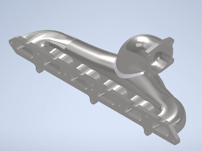
I've got it set up with the offset throttle body mount because the alternator and brake master cylinder block the front and side of the plenum.


I'm going to work on casting the smaller piece that holds the throttle body first. Once I've figured out the process on the smaller piece, I'll work on the Main plenum.
You'll need to log in to post.


