1 2
Albeix
Albeix New Reader
12/17/16 3:15 p.m.

This car started out life as a 2.0L four cylinder unit but after three years of effort now sports a complete Mustang driveline including a Dyno proven 320HP 5.0L backed up by a World class T5 and a 76 Mustang 8" Rear Differential rebuilt with a Limited Slip Differential.

I have a blog about the build at www.capri-perana.com and over the coming days and weeks will be moving the entire content from there to this thread.

Photo of the car in its current state follows.

JoeTR6
JoeTR6 HalfDork
12/17/16 4:18 p.m.

Looking forward to seeing how this beautiful car came together.

HikerDan
HikerDan GRM+ Memberand New Reader
12/17/16 4:20 p.m.

Wow! Looking forward to this!

trucke
trucke Dork
12/17/16 4:22 p.m.

Looks much better with the back dated bumpers.

SkinnyG
SkinnyG Dork
12/17/16 4:35 p.m.

Yay Kaslo! I haven't been there in over 10 years. Beautiful country.

More pics! More pics! More pics!

pres589
pres589 UberDork
12/17/16 5:49 p.m.

Oh good lord that looks nice.

oldeskewltoy
oldeskewltoy UltraDork
12/20/16 12:44 p.m.

interested in front suspension.........

therealpinto
therealpinto GRM+ Memberand New Reader
12/21/16 1:34 a.m.

Nice, another Capri!

I will have a look through the blog during the coming days, looks promising.

My "next Capri project" (Capri people always tend to have one stacked up) is planned for a V8 so I fear this thread will spark some needed but perhaps untimely inspiration :-)

Gustaf

Rodan
Rodan Reader
12/21/16 11:01 p.m.

LOVE IT!

+1 on the backdated bumpers... much better than the enormous later versions, and the Panasports are perfect. I've always wanted to do a 5.0/T-5 Mk1, but the prices on rust free candidates have climbed to the point where I don't think it'll ever happen.

Albeix
Albeix New Reader
12/22/16 10:41 a.m.

In reply to oldeskewltoy:

Hi There

Front suspension on my Capri is entirely stock. I did purchase a coilover conversion kit, but in the end did not have to use it as the Rota wheels with 225-50-15 rubber fit OK for street use. There is about 3/8" clearance on the inside to the strut and on the outside I only had to roll the wheel opening across the top of the wheel arch to clearance the tires.

That 15" tire diameter is virtually identical to the factory 13" tires with factory spec sidewalls.

AL

oldeskewltoy
oldeskewltoy UltraDork
12/22/16 11:09 a.m.

In reply to Albeix:

having owned 3 1st gen Capri's... I rather hated the design of the lower control arms... big massive arms... using the sway to perform double duty (sway bar, and track arm). I have seen a few upgrades.... but I never liked the original design

Albeix
Albeix New Reader
12/22/16 1:31 p.m.

With the Motor installed and the Clutch Cable modified we next set about fitting up the Griffin radiator we purchased for this project. One of the challenges with the Capri is that there is very little vertical room to work with at a shade over 15" After much internet searching we located a Griffin Radiator that fit the bill. The rad is part number 1-25241-X. It is 27.5X15.5 with Top Left and Bottom Right Hose Bibs ala Ford Mustang std configuration. It is a 2 row unit with 1″ tubes. The 87-93 Mustangs have a single core rad with 1” tubes and a total finned area of 445 Sq Inches. The rad above has a slightly smaller finned area, but is a double row rad with 1” tubes so should be more than adequate. The total finned area of this rad is slightly less at 426 Sq. In but with the double row, aluminum construction, it should more than hold the heat even with the beefed up engine.

Photo below shows the Rad in its rough position.

Albeix
Albeix New Reader
12/22/16 1:46 p.m.

Recognizing that the rad is only a part of the cooling solution I set about figuring out how to set up the radiator cooling fans. This turned out to be another bit if an internet research project as I was initially unable to find anything other than a 10" fan that would fit behing the rad core. I ended up hand fabricating an aluminum fan shroud set up for a pair of 10" fans.

Photo below shows the end result of that effort.

In thinking about the shrouds design I decided that I had best come up with a way to close off the holes below the fans when sitting in traffic at an idle as I wanted maximum flow thru the rad core. what I came up with was a pair of small metal flaps made out of ultra light aluminum house flashing.At Idle these flaps are pulled tight to the shroud by the fans thus causing max airflow thru the core but as soon as the car is moving the air pressure opens them up. Works a treat!

Photos below show the flap in both open and closed configuration

Albeix
Albeix New Reader
12/22/16 4:32 p.m.

The next project I tackled was the High Pressure fuel system for the 8 Stack EFI induction.

In the interest of brevity I will leave out all the gory details and leave you with the following schematic of the system as installed.

Suffice to say that once it was all installed the area by the fuel tank looked like an oil refinery with pipes and hoses running every which way but in the end it worked as designed in spite of the appearance.

Albeix
Albeix New Reader
12/22/16 4:48 p.m.

Once I had the fuel system basically installed it was then time to move onto the Electrical system. Once I got the car home and started to peer into the hidden ares behind the dash etc I realized that the wiring harness on the car had been totally trashed by previous owner(s) so decided that the best remedy would be a total replacement.

From my days selling Cobra Kits in Canada I had a left over painless wiring harness from a FFR Daytona coupe which while very different looking is about the same size as the Capri with the result that the harness was a good fit on the Capri. In due course this was all installed and tested and found to be working

Having a wiring harness in the car meant that I could now work on the custom instrument panel I had been thinking about since I purchased the car.

The following in lifted directly from the cars build blog at Capri-Perana.com

One of the things I wanted to do with this car is to do up a custom dash. I had a couple of reason for wanting to do this as follows.

First off whilst the Capri Dash is actually pretty good by OEM standards with a full compliment of the typical gauges, the dash and instruments in the car are pretty tired looking as one would expect after 40 years.

Secondly, I wanted more than the typical complement of gauges in the dash so whereas the OEM dash has a 4″ tach and Speedometer, Fuel Gauge, Engine Temp Gauge, oil pressure and ampmeter Gauge, I wanted a dash with all of those plus an Engine Vacuum Gauge, an ambient air temperature gauge, a Clock and gauges for front and rear hydraulic brake line pressures.

I started this sub project with my favorite medium – poster board – and cut a piece in the shape that the opening allowed for.

I then sat down and spent several hours and about an inch of eraser putting ideas on said paper, After numerous iterations of this I eventually came up with a layout that seemed logical and which suited my aesthetic sensibilities.

So, once that was done the next step was to transfer the poster board dash to a piece of flat steel 20 Gauge sheet and cut it out. Here again pneumatic shears proved to be invaluable.

With the overall shape cut out I laid out the gauge placement and then proceeded to cut the holes using an assortment of hole saws.

Next was to mount all the gauges and then wire them up.

Photos below shows layout, wiring and the end result.

Albeix
Albeix New Reader
1/6/17 12:22 p.m.

Back at updating this thread now that Christmas is behind us.

With the wiring mostly in place and the instrument panel built it was time to install the panel into the dash. Given that the front seats are black leather with red accents I opted to add a red piping around the instrument panel. This serves the dual purposes of accenting and complimenting the seats while at the same time hiding the obvious misfits where the panel is not tight to the dash. (Remember this is a hand made instrument panel) Photo below gives a pretty good idea of the end result.

Albeix
Albeix New Reader
1/6/17 12:36 p.m.

With the dash installed I then moved on to installing the aftermarket heater. Given that the car will only ever see summer time driving I questioned whether I even needed a heater but in the end decided to install one as a concession to those cool rainy summer days when having the windows up results in fogged up windshields

Photos below show the Capri OEM heater and the aftermarket one I installed, Not the size difference. Weight savings is similar to size difference.

Albeix
Albeix New Reader
1/6/17 1:37 p.m.

Engine Initial Firing.

Apologies in advance for the length of this entry, but there is a story here that needs to be told fully in order to allow the reader to understand. This entire process took place over about six weeks but in the interest of brevity I will try to give you the short version which will still be long. That said lets begin.

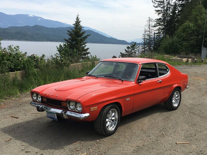
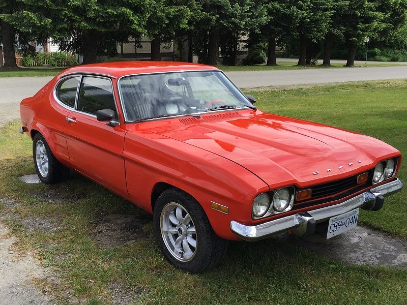
Having worked diligently on the car for the last year and a bit you can imagine how I looked forward to being able to turn the key and have the engine come to life.

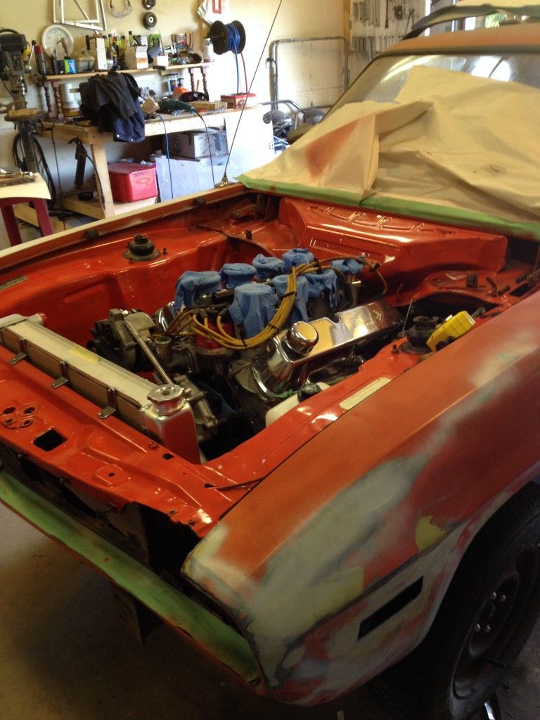
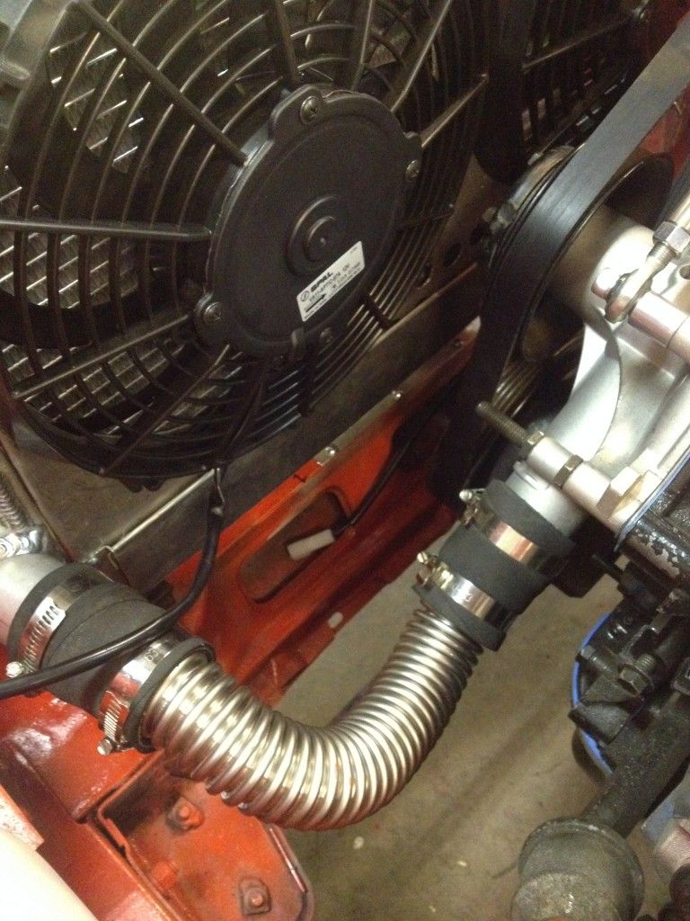
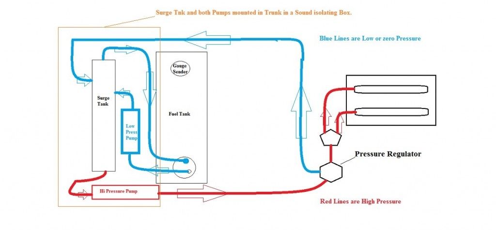
With the fuel system figured out and tested for pressure and integrity, the cooling system plumed and filled and the wiring done and tested it was finally time to bring the entire package to life.

So with a mixture of excitement, and apprehension I hit the key and was rewarded - with about one half seconds cranking and then nothing!

WTF???????

Initially I figured I had a bad ground that had only momentarily connected and then collapsed (electrically) under load so I disconnected the battery and proceeded to check all of the grounds and as insurance added a second engine to frame ground fabricated out of a piece of welding cable. With that done I tried it again.

Same result?????????

At seeing this I stood beside the car and observed the engine while trying one more time. What I noticed is that if I held the key in the start position the engine would initially crank and normal speed then stop and then VERY slowly continue to turn over????

After thinking about this for a while I decided to pull the plugs and see if the engine would turn over without compression. As soon as I hit the key with the plugs out the engine turned over freely and sprayed the entire shop with raw gasoline. The issue was that the engine was hydro-statically locked up with Raw gasoline!!!

Now I was really Puzzled. Remember, I had an Ingelese 8 stack induction system on the engine at this point and this was a new beast to me. I talked to the suppliers tech department and as I would soon learn they gave me their standard advice for all problems related to their EFI being "you have a bad ground somewhere". Checking, rechecking and then doing it all again showed that there was no ground issues??????

As all of this was going on part of the process involved turning on the ignition to check various connections and power sources. Somewhere along the process I noticed that when running the fuel system was at the prescribed 42 PSI but as soon as the key was shut off it immediately dropped to zero. From previous experience with other EFI systems I thought this strange as an EFI Fuel system will typically hold some pressure for a good length of time once the pump is shut off.

At seeing this I contacted the manufacturer to ask about the chance that one or more injectors were stuck open and was told that while possible it was highly unlikely if I had started with a clean fuel tank and new lines (I had), they suggested - wait for it - a bad or missing ground.

Throughout all of this I did manage to get the engine to run but just barely and with so much black smoke that it looked like a diesel with a plugged air filter. After each running session - typically less that 10 mins in length I checked the oil and found it to be overfull and fouled with gas. so we changed the oil an filter. I total this happened four or five times for a total run time of less that one hour.

Throughout all of this my big concern was what the gas was doing to the cylinder walls, rings and bearings and sure enough on the next session the engine developed a solid bearing knock!!!!

ARGGGGGG!

So, in a matter of several weeks and less than 2 hours of running we had burned out a really strong running 5.0L engine. Needless to say I was disheartened.

After pondering the whole situation for several days I called a mechanic friend in Calgary to bend his ear and share my woes. At hearing what had transpired he said in jest, I'll take the 8 stack system off your hands if you want. (He is a mechanic by profession and knows EFI systems well). At hearing this I called his bluff and told him if he sent me everything I needed to put a Holley 4BBL on the car I would send him the entire 8 stack system in trade. We agreed and the deal was done.

Financially this deal made no sense for me as he got about 4-5 times the value that he gave me in return, but from my perspective it made good sense as I did not have to put out more cash for he carb setup and I got an induction system that I understand and can work on.

So, with the deal done I started to dismantle the EFI system and package it for shipment. The first thing I did was unplug the 56 pin connector from the ECU and when I did I noted that one of the pins had been pushed back into the plug! At seeing this I got out the wiring schematic and discovered that the pin that was not connected was one of 5 that controls the injectors!

Upon discovering this I pulled the pin out until its lock snapped into place and plugged the connector back into the ECU. When I turned on the system the fuel system now charged and upon shutting off the fuel pump the presssure dropped from 42lb to 30lb and held like it was supposed to.

So, what was going on is the missing pin was causing four injectors to open and remain open thus dumping raw fuel into those cylinders as fast as the pump could provide it. This was born out by the engine builder who confirmed that when he tore the engine down four of the cylinders were glazed and the rings worn out as a result of fuel washing.

So, after three weeks the rebuilt engine was back, installed, wired and plumbed abd fired right up. It has run flawlessly ever since and though I lament the loss of the sex appeal the 8 stack system would have provided I am more than happy with the Holley/Edelbrock system.

As a final act in this little subplot I wrote the manufacture and let them know what had transpired, what I had discovered and what it cost me. I never received so much as a thank you, apology or acknowledgement I guess I should not be surprised, but a simple acknowledgement and thank you for the comments on their quality control would have been appreciated!

Albeix
Albeix New Reader
1/6/17 4:12 p.m.

Motor Mounts.

When I initially started this project one of the big puzzlers was engine mounts. and after some hours on the internet I came up with a set of steel mounts. In as much as these were all I could find at the time that is what the engine was initially installed with.

Now that I had a running car and all systems seemed ready for initial testing I put a 24 hour permit on her and set off for a test drive.

Several things were discovered including the fact that the steel motor mounts were entirely too noisy and transmitted far to much vibration to the chassis for my liking or comfort. as a result I embarked on a renewed search for a rubber isolated set of motor mounts. The following text is lifted directly from my build blog at www.capri-perana.com

I had found a post on a Ford Ranger forum about using 4.0L Ford engine mounts to install a 5.0L in the Ford Ranger. This looked like a solution that would work in the Capri so I ordered up a pair and set about installing them.

IMPORTANT INSTALLATION NOTES – If you are using this solution you want to order a pair of ANCHOR (or equivalent) 2641 right side Engine Mounts. For some reason the frame mount bolt on the left side mount is positioned such that the mount is entirely too high in the frame to accommodate the 5.0L in the Capri. Also, before you install the engine lengthen the frame pad mounting slot at the bottom as much as possible to allow the engine to sit closer to the front cross member.

To recap the Mounts require an adaptor plate made from a piece of 1/4″ flat steel plate. As shown in the following Pattern. (Note – Do not drill the mount holes until you determine where on the plate you want them – see procedure description below)

motormount Adaptor Plate

When installed in the ranger the end result looks as seen below.

For the Capri I started out with a steel rectangle about nine inches by four inches and drilled the engine side holes at the requisite 7″ spacing.

After confirming that it would fit under the headers, I cut a duplicate out of poster board and installed that over top of the engine mount in order to get an impression of the mounting bolt and locating pin in the poster board This was then transferred to the steel plate.

In that this was all done with the engine in place I ended up having to cut slots into the plate to allow the plate to be installed over the mount bolts. Once that was done I was able to bolt up the plate and lower the engine onto the mount. Doing so showed me that the engine should come down about 1/4″. In considering how best to do this I ended up cutting out a corner large enough to allow the engine bolt castings to go through at each end of the plate where the engine bolts go. I then cut a piece of 1/4″ material to go over the cut out and welded that underneath the plate as seen from below. (See photo below)

This allowed the plate to move up 1/4″ between the engine bolt bosses thus lowering the engine the required 1/4″.

The photo below shows the mount installed as seen from below. When I used the welded on tabs I did have to cut out about 1/4″ along the length against the engine in order to allow the plate to move up the 1/4″.

All in all I am very happy with the finished result and driving the car is now far more enjoyable.

To recap

Use Anchor 2641 Mounts (2)

Adaptor plate is 1/4″ Plate Steel.

Albeix
Albeix New Reader
1/6/17 4:38 p.m.

Driveline Vibration.

With the engine mount situation sorted out I next turned my attention to the drive line vibration that had been present from the initial drive.

Initial investigation showed that the transmission u-joint/Pinion Ujoint angle relationship was entirely wrong.

In a nut shell this was a problem of my own making in as much as when I welded the spring pads to the back axle I was WAY off in positioning them. So after spending the summer trying various solutions, come the fall, with the car off the road for the season I pulled the entire unit and sent the center section off for a rebuild and upgrade to a limited slip unit.

While that was at the shop I cut off the spring pads and re-positioned them more accurately using the knowledge gleaned from my initial set of mistakes.

I have now got the entire assembly back in but have not had an opportunity to retest it other than to spin the Diff up to 40 Mph on Jack stands to mix the Gear lube and friction modifier, but checking both ujoint angles with a digital angle finder shows me that they are now within 1/2 of 1 degree if each other which is well within the industry accepted norms.

Will provide an update on this subject once the car is back on the road come spring.

Albeix
Albeix New Reader
1/6/17 5:13 p.m.

Body work and Paint.

Now that I had the car essentially put together it was time to start working on the body.

As mentioned at the outset the body was structurally very solid, but that does not mean it was perfect by any stretch - Its still not either as it is meant to be a driver not a trailer/shop queen.

The car had hundreds of stone chip, small dents and small surface rust spots that all needed to be taken care of. In addition I needed to add the rear fiberglass fender flares and blend them into the body as well.

Suffice to say this took many days of filling, grinding, sanding and block sanding to get to a point where I was happy with what I had.

At that point I turned my attention to finalizing a decision on what color to paint the car.

Back when I was involved with kit cars I had an PC program built called (Shameless plug here for www.digitalcarpainter.com) that allows the user to identify an object in a photo - like a Capri for instance - and digitally mask off areas like glass and chrome that should not be painted.

With that done the user can then digitally paint and repaint the car in different colours to better visualize what the object would look like in said color(s).

I started with a photo of my Capri in primer as seen below.

After trying numerous different color ideas I settled on what you see below.

And the real world finished product looks as seen below.

In the end when I went to the paint store to pick a color I ended up with more orange than I had digitally choosen, but the digital visualization put me on the right track.

stu67tiger
stu67tiger Reader
1/14/17 10:41 a.m.

Beautiful project! I had a '73 V6 back in the day, same color, so this really brought back memories. I'd often wondered if a SBF would fit in there, since I already had that in the Tiger. But one crazy toy was enough, so I left it mostly stock.

JoeTR6
JoeTR6 HalfDork
1/14/17 7:25 p.m.

This car makes me happy. I like the bright orange-red. If I can find one of these that isn't too rusty, it will be my next project.

Nice work.

Albeix
Albeix New Reader
1/21/17 7:34 p.m.

HalfDork

Thanks for the compliment. I really enjoyed building The car and I think I enjoy people's reactions at shows and on the street even more. :o)

Nick (Bo) Comstock
Nick (Bo) Comstock UltimaDork
1/21/17 7:47 p.m.

Absolutely beautiful! I bet it's a blast to drive too!

1 2

You'll need to log in to post.

Our Preferred Partners
vrSiJDtwuwep7U81urq7bX4ZYjXwYg5K790yZGjNATRrKklGWA8VYk4BXMLF8mYP