Are you going to increase the track and or add flares while doing the front suspension? If so could you also move the front wheels forward. This would give you two advantages. First it would effectivly move the engine further back in the wheelbase to improve weight distribution, second it would give more room around the front of the engine. Just an idea.
I will increase the track slightly (a couple of inches), but not to the point where I would need to add flares. The wheelbase is staying the same, though, mainly because I like for the wheels to be centered in the wheel arches. Room in the front of the engine won't be an issue with the Miata lump in there. If I need room, I'll push the engine back into the firewall. I have all of the flexibility I want at this stage, since driveshaft length is whatever I want it to be (i.e. I have to get a new custom shaft made anyway) and my firewall is pretty much not there.
I'm starting to get fired up about this project again. I have some chassis steel ordered, and I should be able to get some work done this weekend. More pics will come soon, I promise! My wife got me a new digicam for my birthday in January... :D

jmc14
Reader
2/4/13 12:54 p.m.
Great build. I'll be following it.

Winston
HalfDork
2/21/13 11:38 p.m.
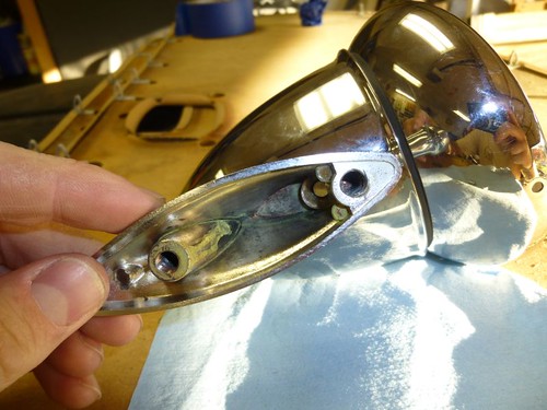
Last year (IIRC), I traded some BMW things to irish44j for a pair of these:

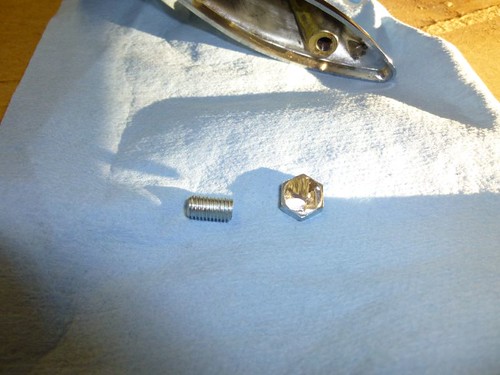
Last weekend, I decided to mount them on the Spitfire. Unfortunately, the threads weren't in the best shape so I decided to convert them to studs:
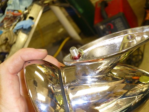
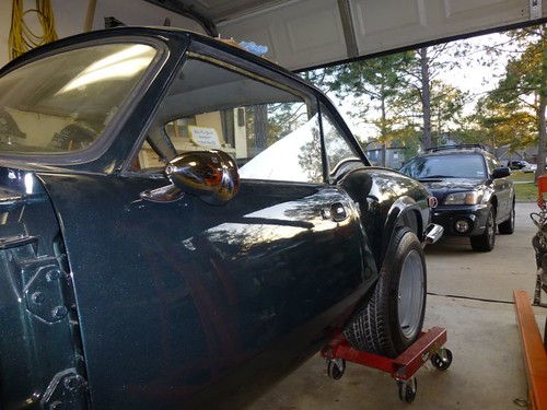 Yeah, they're mounted too low because I used (most of) the holes for the stock mirrors. They're pretty much for looks anyway since the actual mirror is about as big as a bottle cap... and they look damn good. Thanks, J!
This weekend we get serious. The chassis will be cut, and new steel will be welded.
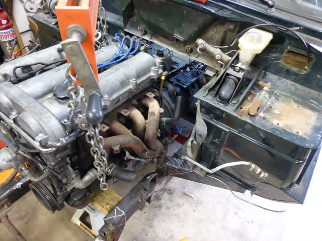
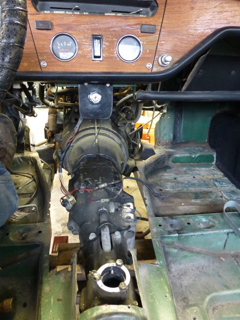
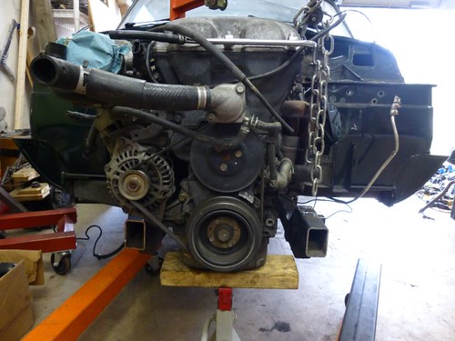
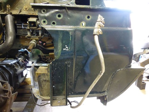
First off, the current state of the engine bay (never mind the blue tape down the middle):
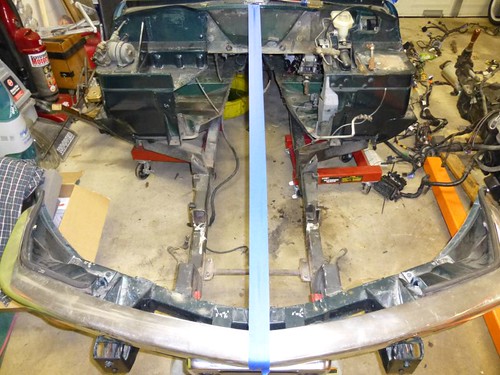
A bit more bare than the last time... progress, such as it is.
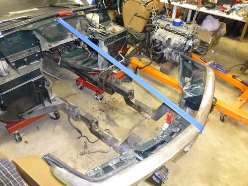
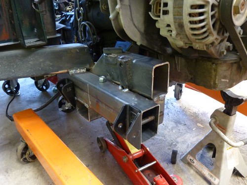
In the spirit of cutting once and measuring twice, the Miata drivetrain will be placed in the chassis to make sure my cuts are made with as much information as possible, so I drug the '94 Miata drivetrain alongside the Spitfire, performed some eyeball measurements to make sure I'm not totally berkeleyed with this build, drank some beer, and began removing the wiring harness from the engine (labeling as I go... I still have my wits about me):
Tomorrow:
-
finish removing the wiring harness from the engine
-
suspend Miata drivetrain in chassis
-
eyeball things for 3 hours
-
finally say "berkeley it" and decide on what to cut
-
remove drivetrain
-
cut and tack new front suspension cradle into place (well, the base anyway... assuming that I will accomplish more than that would be overoptimistic)
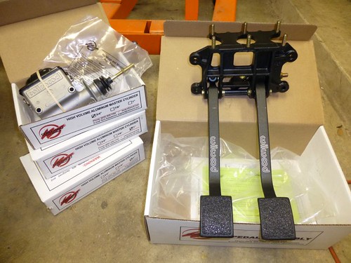
For tonight, I leave you with a pic of the sweet Wilwood pedal set that my lovely wife gave me for Christmas:
Winston
HalfDork
2/22/13 12:31 p.m.
The fruit of this morning's labors:
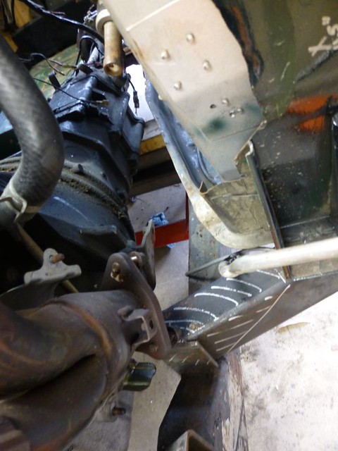
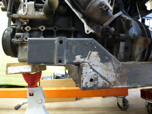
The driver's side outrigger will be relocated so that the exhaust can dump outside of the chassis rail. I just have part of it marked in Sharpie because I was considering just cutting it, but recreating it with a new chassis attachment point will give me more room.
Things look good from a bonnet clearance standpoint.
Passenger side looks good too, I just need to grind down that protrusion near the clutch slave cylinder bleeder.
Plenty of clearance for a decently-sized transmission tunnel.
Oh, and this thing will have about 16% longer legs than a Miata:
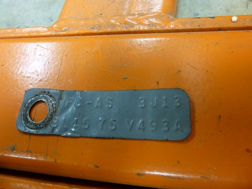
That's a 3.45 ratio vs. the 4.1 ratio in the Miata, and the "L" confirms that the diff is a Traction Lok. So I've got that going for me, which is nice.
I'm 6.2 and driving my GT6 is like a go-kart.
In the UK lots of people drop in FORD DOHC engines so that this will work great.
Hmm turbo and 6spd manual... Just putting it out there...
And a roll bar.
Not just for protection but it will help stiffen the body up a touch.
A.
AndreGT6 wrote:
And a roll bar.
Not just for protection but it will help stiffen the body up a touch.
A.
Maybe a turbo and 6-speed at some point (turbo before 6-speed, for sure). Definitely getting a roll bar.
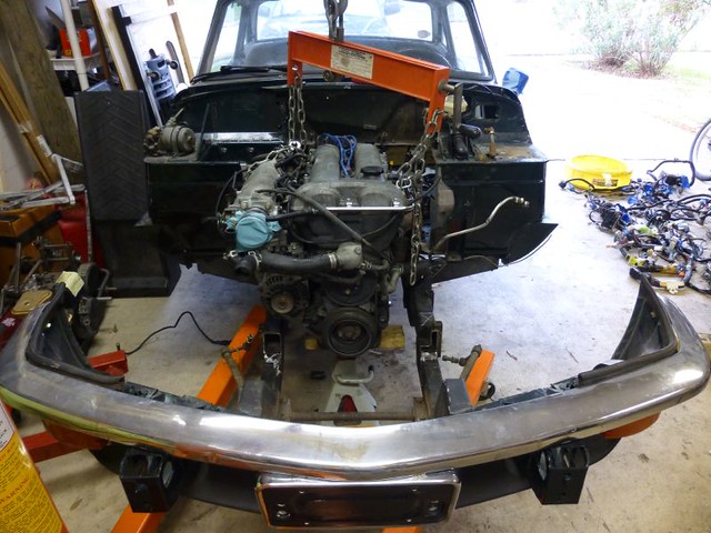
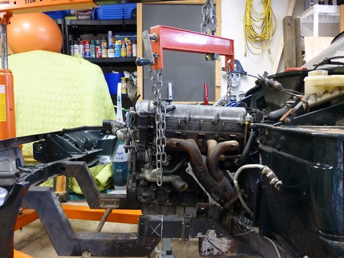
Well past the point of no return:
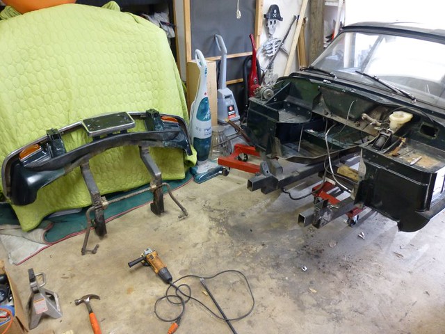
Got the frame rails cleaned off (removed old motor mounts and the offending parts of the shock tower supports) and once again mocked up the 1.8 lump. I've got about 4" on each side between the frame rails and the oil pan.
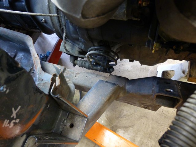
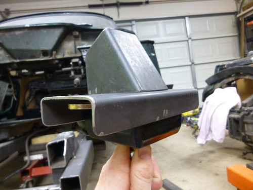
The oil pan profile will closely mirror the frame rail profile:
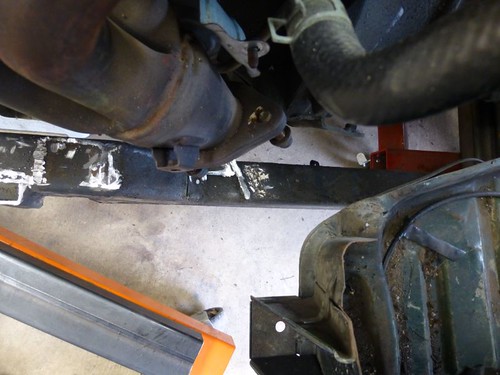
Plenty of room now for the exhaust to dump outside the frame rail:
My 8-yr old son helped me out by unbolting the pedals and master cylinder. This whole shelf will come out , to be replaced by a fresh sheet of steel with holes and cutouts appropriate for the Wilwood pedal set mentioned earlier.
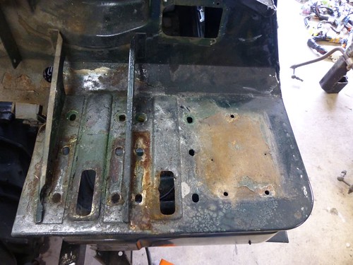
A good look at the hack job the the original builder did on the driver's footwell. I'll smooth out the cut lines and weld in fresh sheet metal.
Metalwork weekend. I love welding 
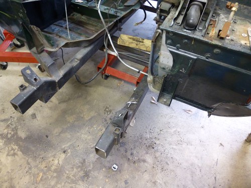
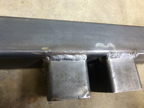
These new, wider chassis rails will allow the use of the Miata steering rack, unaltered.
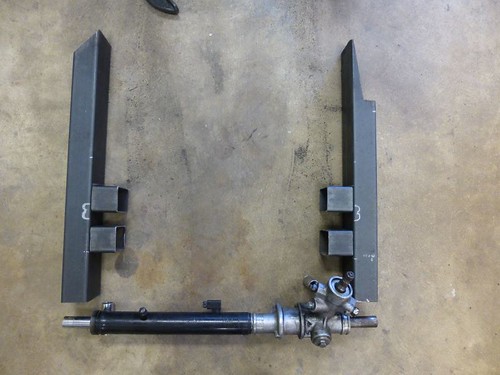
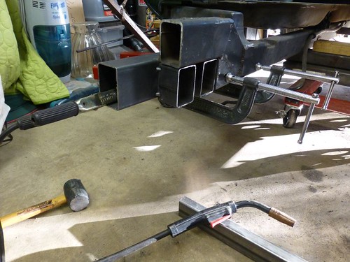
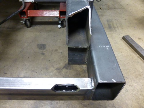
The two "ears" on each rail provide additional structural support. I'm going to be using a belt-suspenders-superglue approach to making sure this rail splice is strong and safe. I'll have the ears, welds along all possible joints between the old and new rails, and through-bolts. Here the ears are being mocked up and tacked to ensure fitment.
Completed rails. They are asymmetrical because the driver's side rail has additional clearance for the exhaust.
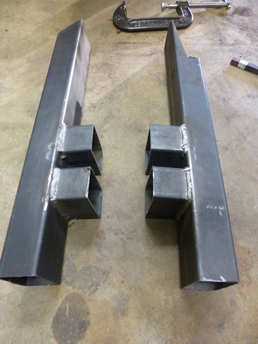
I'm pretty happy with these welds. This stuff is about as thick as my welder can handle without pre-heating:
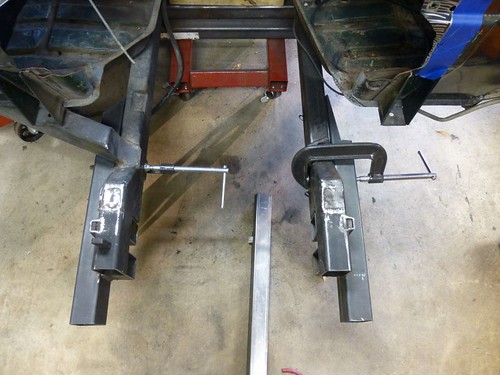
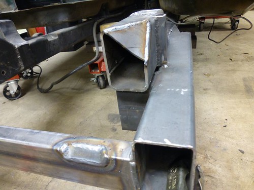
Both rails clamped in place. I won't start to weld them in until I've added the crossmember across the font, which will support the steering rack.
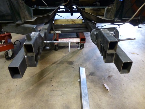
Top view. You can really see the additional clearance for the exhaust that the driver's rail cutout provides. Some of the body sheet metal will be trimmed as well.
It's amazing how much time this stuff takes. With the time I spent, it feels like I should have more to show for it.
This coming Friday is a day off for me, so I'll get the steering rack crossmember in and hopefully get started on the suspension towers.

CLNSC3
HalfDork
3/4/13 1:42 a.m.
Theres a swap I haven't seen before, awesome work! You ever sell that T5 we were talking about a few months ago? Looking forward to updates!
Thanks! From what I can tell, Spitfire engine swaps in general are uncommon. Here's another Mazda BP (Miata) swap that I know of:
http://forum.britishv8.org/read.php?3,30104
I did sell the V8/T5 to a fellow GRMer and LeMons racer shortly after I bumped my sales thread here on this forum. It freed up some much needed room and cash!
More metal work today!
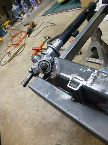
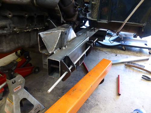
First task was to get the steering rack support in place. Here it is, with the rack itself mocked up in about the right place.

Even though the rack support beam is an inch shorter than the chassis beam, I still have some fouling around the pinion housing (or whatever you call it). I'll have to notch the support beam to get the pinion shaft angle that I want.
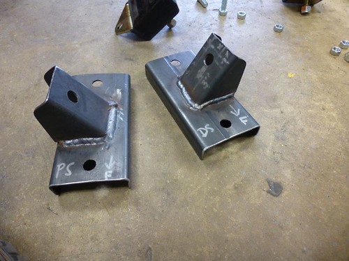
I've also begun making the motor mount adapters. These will allow me to use a Jeep/Universal motor mount (Energy Suspension in this case) vertically, thereby decreasing the overall width of the motor mount package.
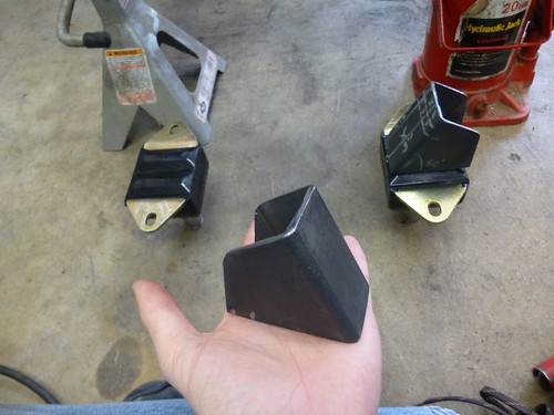
 There will, of course, be a plate between the angled piece in the photos and the motor mount. The angled piece will be welded to the plate, and the motor mount will bolt to the plate on the top. A pair of chassis mounts will be welded in for the motor mounts to bolt to on the bottom side.
Motor mount adapter plates, fabbed from 14 ga. 2"x3" tube, just like my chassis extensions. I just cut off a 6" piece of tube and then split it lengthwise (cutting on the 2" faces). The motor mounts fit perfectly inside.
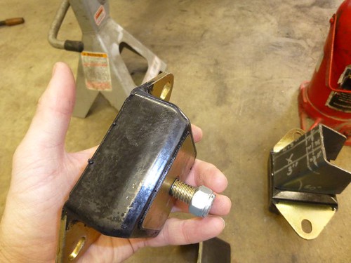
What each one will look like when finished (but with holes, of course). Also, I will need to put a thick washer in between the mount flange and the plate, to take up the space you see now. The urethane "pillows" bulge up proud of the motor mount flange.
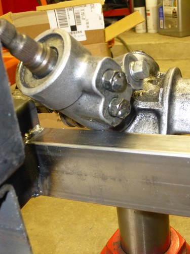
Notches for the steering rack, cut and then filled:
Good clearance for the u-joint now, and the pinion angle is much better. My goal is to have only two u-joints between the steering column and the rack, and to keep them as straight as possible.
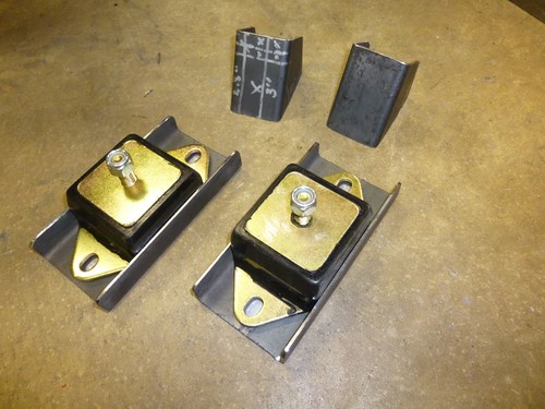
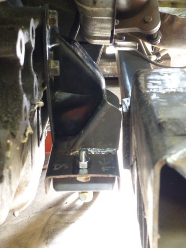
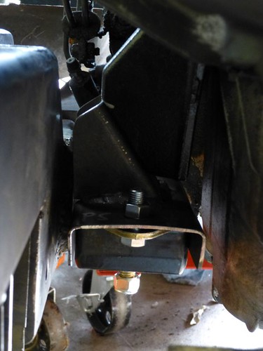
Completed the motor mount adapters.
I had to grind off a little from the angled portion of the adapter, bringing it to 55 degrees (from 60), in order for the mount to be at a right angle to the chassis. Not sure where the difference was (I measured the Miata motor mount brackets at 30 degrees), but both sides needed 5 degrees removed.
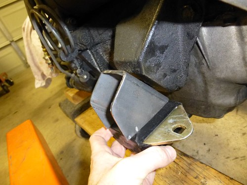
Driver's side clearance. I'll need to grind down that plate on the old chassis to give me a little more room. It no longer serves a purpose anyway since I removed the outrigger it was supporting.
Passenger's side. There's about the same amount of clearance as on the driver's side, even though the camera angle doesn't show it.
I'm going to drop the engine a little lower in the chassis to get it totally level and make the chassis brackets for the motor mounts easy peasy. Unfortunately, that also means I'll probably have to notch a good portion of the steering rack support so that the oil plan clears it. The upside is that this car is going to have awesome Ackerman -- the opposite of how the Spitfire was originally built
Looks like things are coming along great!  That Ackerman fix makes all the difference in the world in tight turns. BTDT.
Thanks! I'd really hoped to get started on the suspension (brackets, towers, etc.) this weekend but things are going a little more slowly than I had anticipated. Making sure that you get things right when fabricating just takes time.
Winston
HalfDork
3/25/13 10:16 a.m.
This thread has been idle for a couple of weeks, but I have not been. I've been using the "Wishbone" suspension analysis program familiar to many Locosters, trying to come up with the best layout I could. The locostusa.com site seems to be down right now, but here is the link to the program:
http://www.locostusa.com/yahoo/Wishbone_setup.exe
I think I had honed in on a pretty good setup, but there were a few suggestions on the locostusa.com board that I was going to try out before I finalized my geometry.
Then, rallycross happened.  I remember having a lot of fun back in 2008 when I last rallycrossed, but I had forgotten exactly HOW MUCH fun it is.
Yep, RallyCross Spitfire. Get ready.
Some weekend when I'm not racing I need to drive south and see this creation in person. If you do end up rallycrossing it, it will surely be the absolute coolest car out there. Are you going to be 4x100 Miata bolt pattern or 5xsomething. I happen to know a guy with 4x100 wheels and snow tires that you could totally borrow. 
Winston
HalfDork
3/25/13 12:31 p.m.
Just tell me when you can come down!
Currently, the front end is 4x100 (obviously, since I'm using Miata spindles), so I just need to figure out the back end. The studs are at 4x95, and the stud holes for 4x10⁸ are still there (the rear end is a narrowed Ford 7.5" out of a Fox-body Mustang GT). My options are:
-
Run an adapter-spacer from 4x95 --> 4x100;
-
Get new axles with hubs drilled for 4x100;
-
Stay with the different bolt pattern on the rear wheels.
Right now I'm leaning toward Option 3. I'm going to have very different offsets between the front and rear wheels, so I can't really swap them anyway.
Option 3 makes sense. However, if you find yourself trying to run a square setup for rallycross and you find that you need a spacer to move the rear wheel out, it might work out to have that spacer also be an adapter to 4x100. Maybe. I'm currently salivating at the thought of that car in the dirt. Keep burning wire my friend.
As requested, much more wire burned this morning. But first, let me back up a little bit. As I mentioned earlier, I've been using the Wishbone suspension analyzer to try and design/optimize my suspension geometry virtually, prior to building it. After I got some good numbers, I realized that my steering rack had to move MUCH closer to the driver/engine/Front LCA bracket. This involved cutting out the nice crossmember I welded in earlier, as well as making the frame notch even larger. Done!
Except that I still wasn't able to get the rack as far back as I wanted, because I wanted that "ideal geometry" I had worked so hard for in Wishbone. sigh Moving the rack further back to achieve it would mean that the engine would have to go back further, which would push the shifter back further. The shifter is already at the point where I will probably have to cut and angle it, and I don't really want to construct a remote shifter. Plus, pushing everything back would increase the severity of my driveshaft u-joint angles, which are already approaching "questionable."
Enter design paralysis, the silent killer of major automotive projects.
Then, the ghosts of rallies past inspired me to say "berkeley it," live with "good enough," and press on.
The rack will sit about 1" ahead of the tie rod ends instead of 0.4" behind them; however, due to the Miata spindle geometry I will still have positive Ackerman! Nice for the street, fairly inconsequential in the dirt.
I also decided to use the Spitfire's bolt-in control arm bracket design; this will allow me to adjust camber with shims if needed, just like in the Spitfire, and it will keep me from worrying about my bracket welds failing due to poor penetration (those brackets are THICK... you'd think the Spitfire weighs 5000 lbs).
P.S. Cobalt drill bits are awesome, and worth the price IMO . They cut mild steel like buttah.
BTW, don't know if you can still access the insides of those tubes, BUT:
The Spitfire uses captive spacers inside the frame for the control arm bracket attachments.
This does two things:
1) Prevents the frame section from collapsing or bowing when you tighten down the nuts on the attachment studs.
2) Creates solid clamping force between the stud and the frame wall on BOTH sides, distributing the loads, and solidly attaching the brackets.
The spacers are STRONGLY recommended, especially if you anticipate any spirited driving.
They don't need to be anything fancy, simple metal tube cut to fit inside the box section,
then just a tack bead to keep them attached.
Carter


