1 ... 9 10 11 12 13
Doc Brown
Doc Brown Dork
6/16/16 9:40 p.m.

In reply to stafford1500:

So far the car has been running slightly on the hot side however the cooling fan only needs to be switched on for a min or two during the daily commute. I think the current sized openings really ought to be about right. The perforated panel idea might just be the ticket, I'll need to do some math and stuff and see what would work.

At some point I also need to see how bad I'm berkeleying up the air conditioning. Might really need to gin up some kind of adjustable grill....

alfadriver
alfadriver MegaDork
6/17/16 7:17 a.m.

In reply to Doc Brown:

Lots of cars with similar grill sizes have them. Namely the Fiesta.

Apexcarver
Apexcarver PowerDork
6/17/16 7:31 a.m.
Doc Brown wrote: Might really need to gin up some kind of adjustable grill....

Computer controlled active aero!

RossD
RossD UltimaDork
6/17/16 8:13 a.m.

Putting a couple of bellmouths is way more efficient than a perforated opening.

ASHARE ED1-1 vs CD6-1

https://www.scribd.com/doc/190092313/Duct-Fitting-Loss-Coefficients

C_o * (fpm/4005)^2 = pressure drop in inches of water column

The fpm is just converted from the mph that the car is traveling.

stafford1500
stafford1500 GRM+ Memberand Reader
6/17/16 9:05 a.m.
RossD wrote: Putting a couple of bellmouths is way more efficient than a perforated opening. ASHARE ED1-1 vs CD6-1 https://www.scribd.com/doc/190092313/Duct-Fitting-Loss-Coefficients C_o * (fpm/4005)^2 = pressure drop in inches of water column The fpm is just converted from the mph that the car is traveling.

While I agree that the efficiency AT THE INTERFACE is better with proper bellmouths, the downstream effect of more/smaller holes provides a better ultimate distribution at the face of the radiator core after it passes the relatively short ductwork length. Additionally, most of the perforated sheet materials are punched and therefore have some small bellmouth effect on one side. Just make sure that is the side facing the incoming air and you have increased the efficiency over the theoretical square edged hole in a thin sheet. Proper belmouths are less efficient as the length of the tube behind it is reduced, which in the case of a thin sheet is quite short in comparison to the hole diameter.

The ultimate solution is to redefine the ductwork so that the inlet area is spot on to the require opening area and have the ductwork faired in from the inlet to the radiator face. However the experiment here was to use the existing inlet and try to reduce the open area to a functional minimum. This is a project with actual measurable changes in the world with lots of other data noise, so I suggested a reasonably simple solution to the not-so-simple issue being presented.

I do spend quite a bit of time fine tuning these sorts of inlets and sorting out the best configuration for cooling, which requires the theoretical understanding, but also the need to be practical and tuneable.
If I were allowed by the ruleset I work from, I would absolutely implement a variable inlet system.

RossD
RossD UltimaDork
6/17/16 9:22 a.m.

In reply to stafford1500:

Agreed. I design HVAC ductwork and do not do any fine tuning.

simon_C
simon_C
6/17/16 8:23 p.m.

Sorry if this response is a little late, but i had to wait 24 hours to respond after creating an account (I've been lurking for a long time)

A front airdam like that metro shown a few posts back will give you some pretty good gains on the aero front. I would avoid going to the donut spares as they will simply be unsafe to drive on, especially in wet or panic conditions.

If you want to lower your rolling resistance, i would invest in a set of 1st-gen honda Insight wheels, which IIRC are 4x100, narrow, have a nice aerodynamic face to them and are lightweight. You should be able to find cheap sets on car-part.com. Other options I would consider would be Honda CRX HF phonedial wheels (aerodynamic, narrow, and fairly light), VW teardrop wheels (aerodynamic, but not terribly light), or steel wheels with moon-caps (heavy, but aerodynamic). Couple any of these with some 175/65-14 Michelin Defender LRR tires inflated to their max-rated PSI, and you should see some pretty good differences.

I would also look into building some form-fitting aero skirts for the rear wheels, it should make a difference as well.

As for the cooling, why not plumb those brake ducts in the lower lip to the front of the radiator? They're already open, and are now just blowing air under the car, rather than somewhere useful. Have you also enclosed the area around the radiator? The miata is known to have pretty piss poor air control to the rad, and there are numerous aftermarket kits to improve this, so the controlled air flow from your aero grill plate actually goes where it needs to, through the rad.

Overall, I love this project and its really interesting to see how efficient you can make a fun car, and still keep it fun, on a budget.

SJLucky
SJLucky
6/22/16 8:28 a.m.

great thread, why not consider something controlled by the ECU for example:

http://ecomodder.com/forum/showthread.php/piwoslaws-peugeot-307sw-modding-thread-9040-5.html#post137288

Doc Brown
Doc Brown Dork
6/22/16 8:24 p.m.

In reply to simon_C & SJLucky:

Welcome to the forum!

I apologize for the lack of updates. Been busy with home improvement projects. The updates should resume soon.

Stay tuned!

Doc Brown
Doc Brown Dork
7/17/16 3:34 p.m.

The vacation and home improvement project are over....but before we continue with the aero mods, lets see what else is brewing.

....................berkeley DIS!

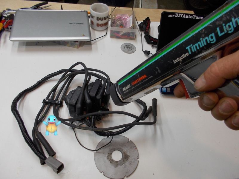
At this point I'm not sure what has me more confused... the GM DIS or the pokemon phenomenon. I ain't got time for the later so let's do something about the DIS.

The GM DIS is awesome in so many ways. cheap and simple.... but in the end it serves two masters....and we cant have that. The GM DIS has the ability to receive timing pulses from the ECM or it can use its built in timing curve. The problem is, I'm not 100% certain what mode the DIS is in and any given point. A five volt bypass signal is used to force the DIS to use ECM timings signals, however if the ECM signals arrive at the wrong time the DIS will fall back and use its built in curve. Its actually quite simple with the single exception that there is relatively no setup info available on the Megasquirt forums. There are a dozen or so ways to configure the DIS for satisfactory results, but so far i haven't really settled on what works best.

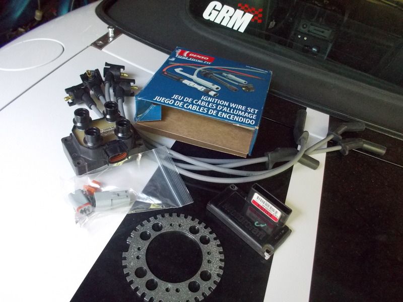
The Ford EDIS4 appears to be the the go-to device for all the cool kids, so in this instance I will chose not to take the road less traveled and go ahead and do something sort of normal.

The EDIS4 was pulled from a 90's vintage Escort during a past pick & Pull adventure. The EDIS cost twenty something bucks. A 36-1 wheel was sourced from Ebay for a mere $32.00. At the same time I also scored a set of Denso plug wires for $19.00 and a Deutsch 2x3 connector set for $12.00.. not too shabby.

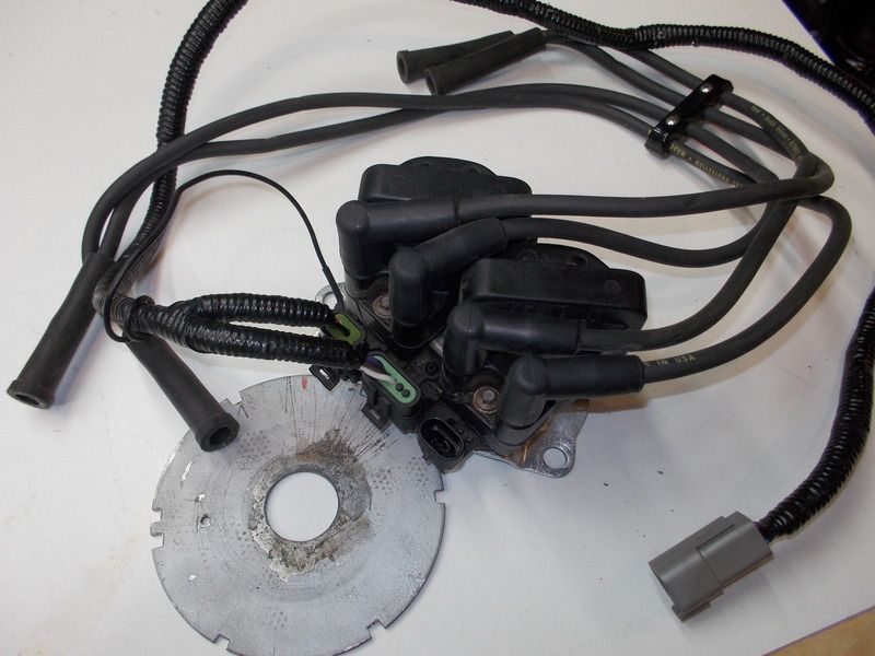
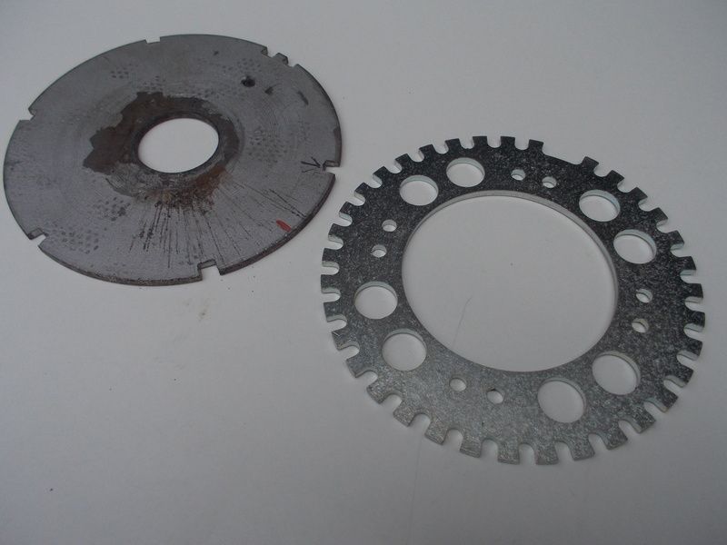
The 36-1 EDIS wheel is a few thousandths larger than the GM 7X DIS wheel... sweet! Unfortunately the hub center ain't even close...

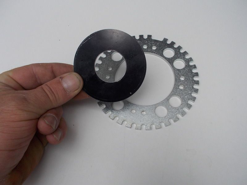
An adapter was ginned up on the lathe to get the 36-1 wheel to fit the custom hub on the B3 engine. I love it when a plan comes together

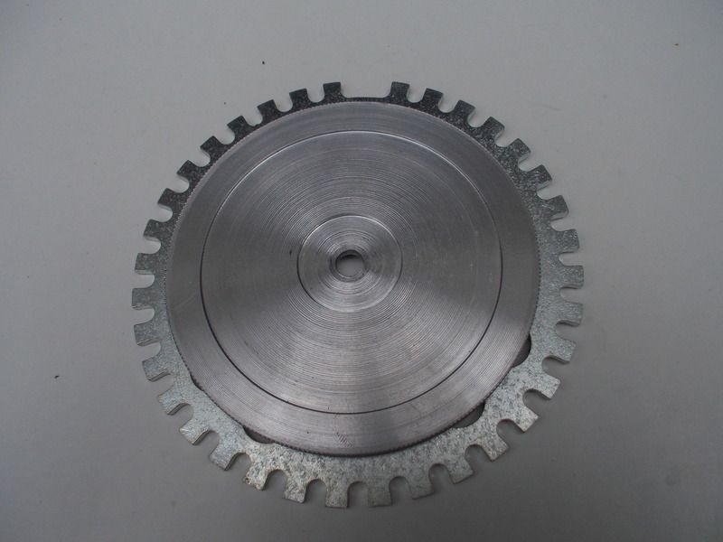
An additional slug of aluminum was machined to hold everything together.

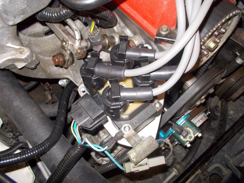
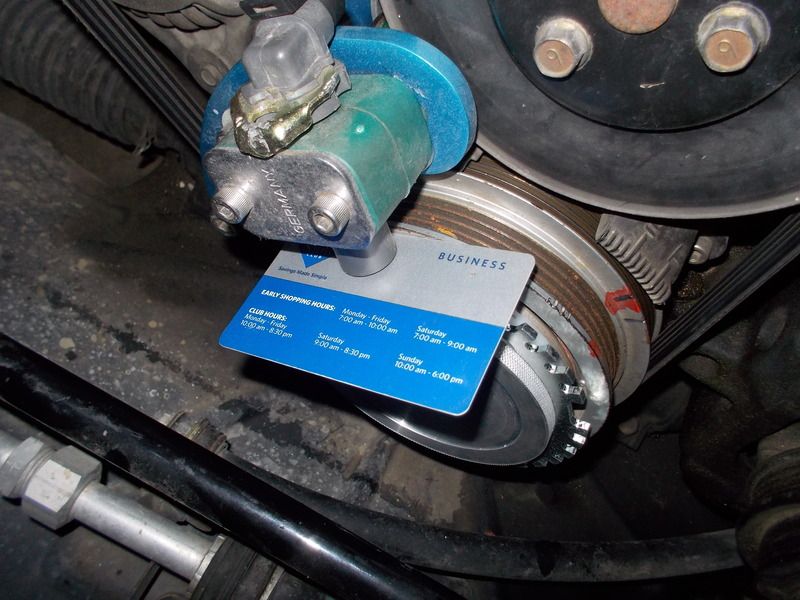
A SAM's membership card is used to set the gap for the crankshaft sensor. The 36-1 wheel is positioned nine teeth ahead of the missing tooth with the engine at TDC. This position will put the ignition at 10 degrease BTDC with zero offset in the Megasquirt setup panel. All this info was readily available on the Internet so no guessing was required.

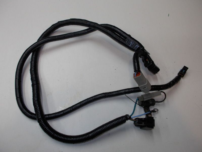
A custom sub harness was fabricated to mate the EDIS4 to the wiring previously set up for the GM DIS. The rest of the Megasquirt harness required no additional modifications.

The EDIS module nests neatly on one of the stock Miata brackets

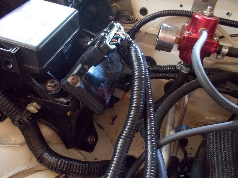
The EDIS coil pack mounts the the bracket previously occupied by the GM DIS. Note the capacitor was also poached from the Escort. The capacitor helps to shunt any EMF that may develop.

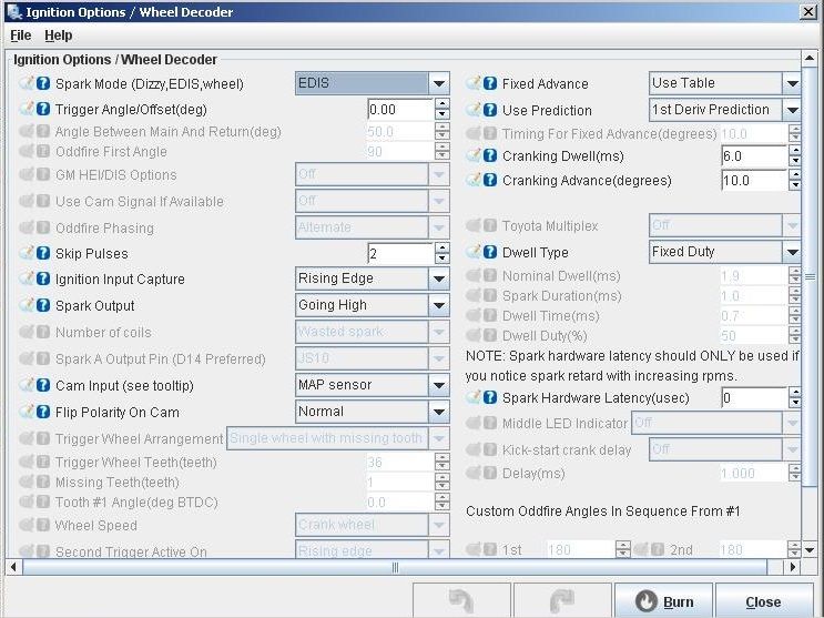
The EDIS was configured in tunerstudio with a few clicks of a mouse. At this point all that was left to do was twist the ignition key and see if this montage of parts work as expected....Yep!, the engine started right up.

Stay tuned!

beans
beans Dork
7/17/16 6:07 p.m.

I had no idea you were in the A2 area... You're only about 30 minutes from me in Toledo! I'd love to check this thing out in person.

Doc Brown
Doc Brown Dork
7/18/16 5:30 a.m.

In reply to beans:

The Doc Brown residence is a mere 25 miles west of A2. You're more than welcome to stop by for the full tour.

Doc Brown
Doc Brown Dork
7/23/16 2:08 p.m.

Its berkeleying hot today ....perfect opportunity to enjoy some cool air conditioning and update this project.

in the last episode the GM DIS got voted off the island and in its place, a Ford EDIS-4 was installed.... now for the rest of the story.

The new ignition system makes the little B3 run different... not better, not worse.... just different. The first thing I noticed is I can dial in more advance before the engine starts complaining... I have thoughts and theories but in the end it is still a mystery. I haven't given up on the GM DIS, it will be installed on my neighbors Ford 9N tractor.

Ok, so I'm happy with the EDIS, what next?........Camshaft timing! But before we explore this subject, I should try and explain how I' evaluating any adjustments....

A few post ago, I went into detail on how the Megasquirt was modified to sound an alarm when the engine temp went into the danger zone. At the same time I also rigged up a second alarm that would activate based on throttle position angle. This second alarm is mostly for research and development for the drive by wire system that will be implemented soon. Anyway, the throttle position alarm is also a useful tool for tuning the engine at highway speeds. After pouring through a lot of data, I determined the best fuel economy for this engine is at a throttle angle of 10% or less. With this information, I went ahead and set the alarm to go off at 11% and above. Although it is berkeleying annoying, I managed to drive the car for several weeks with the alarm blasting almost continuously. The goal was to tune the engine to make the most power at 10% throttle.

When I started this experiment, ten percent throttle translated to 50 miles per hour... that sucks. After fiddling with the camshaft timing I was able to get the car to go 65 miles per hour at 10% throttle angle.... mucho better.

Advancing the camshaft really brings the little B3 alive. So much so, the clutch was having a tough time keeping the power connected to the wheels.... unfortunately this shifted the power band to a less than optimal range and top speed was 50 miles per hour at 10% throttle.

Retarding the camshaft produces lackluster performance( yawn)...but amazingly the top speed increased to 65 miles per hour at 10% throttle.

Taking away some of the ZOOM ZOOM for better fuel economy sucks, but that is the nature of the project. For now I'll live with it.

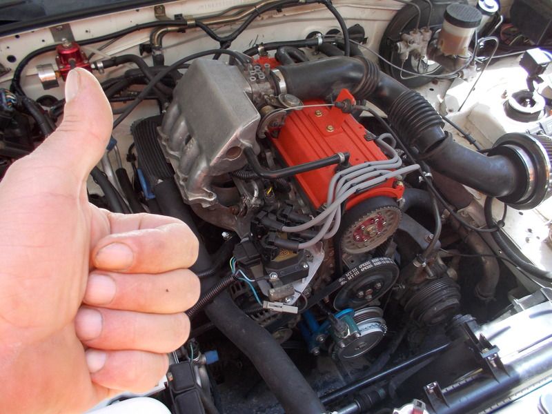
Thumbs up for the EDIS-4

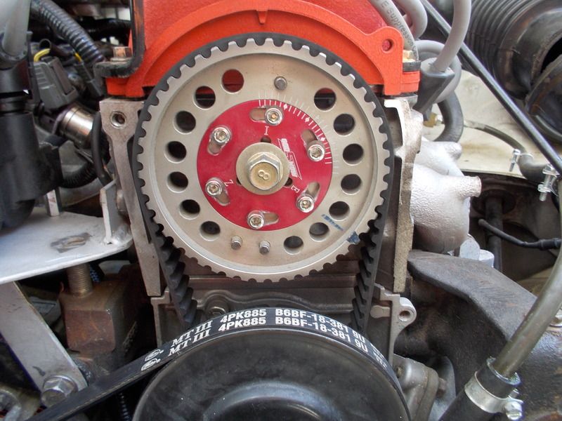
Although I'm on the tail end of the experiment, the sweet spot looks to be about 1 tick retarded on the camshaft. I have no idea what this translates to in degrees.

BrokenYugo
BrokenYugo UltimaDork
7/23/16 2:14 p.m.

Isn't that a vernier scale on the pulley?

Doc Brown
Doc Brown Dork
7/23/16 3:53 p.m.

In reply to BrokenYugo:

Looks to be a scale of some sort, I have no idea how it translates into degrease.

simon_C
simon_C New Reader
7/25/16 12:44 a.m.

On that type of pulley, it's 4.5deg for each inner tick (hub), and 5 deg for each outer tick (gear ring)

These are cam degrees, btw. Just double for crank degrees.

Heres a video on how to read a vernier scale https://www.youtube.com/watch?v=FNdkYIVJ3Vc

Zomby Woof
Zomby Woof PowerDork
7/25/16 7:58 a.m.

In my experience, those adjustable sprockets cannot be trusted. They work fine, but the scale may not have any meaningful relationship to crank degrees, which is how you measure cam timing. In other words, you're slightly retarded now, but from what? Unless you degree it off the crank, you don't really know where you are. You could be advanced. I think the last one I checked was off by 6 degrees.

Doc Brown
Doc Brown Dork
10/19/16 12:57 p.m.

Whelp, once again not much happened with the Miata this summer and unfortunately I probably wont finish many more experiments before the snow starts flying.

After installing the EDIS-4, the Miata more or less spent most of the summer in the garage. The car runs great but due to job obligations, I elected to drive the Saturn.

In this update, the camshaft and ignition settings have remained the same and I focused on the heated throttle body.

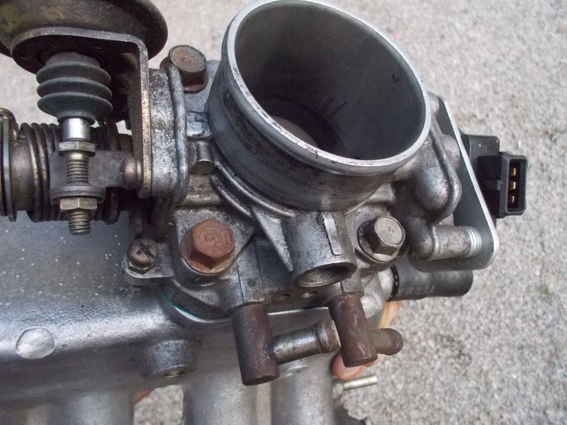
The stock Festiva throttle body allows coolant to flow through the device and will raise the air temperature going into the engine. What effect this heat had on performance and fuel economy was something I wanted to find out.

The throttle body heat circuit was bypassed and right away I noticed the engine sounded different after it was warmed up. Interestingly enough, I was able to detect a slightly stronger bark to the exhaust on acceleration. Its hard to say, but it felt like the engine was making a bit more power. After a week or so, the data indicated this mod had positive effects on fuel economy. I was actually a bit surprised.

To confirm the mod was actually causing the increase in fuel economy, I went ahead and put the throttle body back into the coolant circuit. Yep, the heat seemed to change the exhaust note and the economy dropped slightly... interesting...

Well, the data sort of speaks for itself and the throttle body was once again removed from the coolant circuit.... and sure enough I saw an increase in fuel economy.

Stay tuned!

DDT
DDT New Reader
10/19/16 4:02 p.m.

Cool to see you playing with it again, can't wait to see- final aero reaults, turbo possibilities, comprehensive ignition tuning, other random things like the iat tuning.

simon_C
simon_C New Reader
10/19/16 6:14 p.m.

hey you're still alive! I'm glad you still have this project going. Looking forward to some more updates and aero mods :D

RossD
RossD UltimaDork
10/20/16 8:25 a.m.

With regards to timing and 10% throttle: is there any way to make an algorithm to change the timing with respect to vehicle speed? Are there any tone rings on the Miata? You could do a simple reset schedule. Interpolate between the two set points and make the timing constant before and after the max/min of the interpolation.

Doc Brown
Doc Brown Dork
10/20/16 10:30 a.m.

Thanks for the encouragement guys,

In reply to RossD:

I'm not certain what you are asking is possible without revising the code on the Megasquirt. Anyway, at this point that is way above my paygrade

On a happier note, I did develop a tool and strategy to sweep the ignition timing +/- 10 degrees in real time. I have used the tool on the dyno with interesting results. In theory, the tool can be used to safely fine tune ignition timing while driving. In the next update I'll have the tool installed in the Miata and I'll do a write up with schematics.

Stay tuned!

RossD
RossD UltimaDork
10/20/16 11:16 a.m.

In reply to Doc Brown:

No need for a frowny face. You do things I can't do all the time. Like most the stuff in your build threads!

Is your tool a mechanical device or software based?

Doc Brown
Doc Brown Dork
10/20/16 11:57 a.m.

In reply to RossD:

Its actually quite simple, I was shocked that this hack hasn't been published before in the megasquirt community.... although it has some degree of risk and is temporary.

The tool is a simple box with a potentiometer and a push button. The pot is wired into the megasquirt to replace the air temperature sensor. The trick is to calibrate the pot to represent ambient air temp when the pot is centered. This bit is tricky because ambient temps obviously vary quit a bit.. so on some applications this may cause more problems... especially on turbo cars.

Anyway on the B3 Miata, the air temp is more or less stable once the car is moving so this hack should work on the car as well as it did on the dyno.

Once the device is wired and calibrated then some shenanigans must be done with the air temp timing retard feature in tuner studio. A huge offset is needed but when the pot is centered the offset is nulled. With the large offset, twisting the knob on the potentiometer fools the megasquirt to add or remove timing.

The push button mentioned earlier is wired into the engine temp sensor and when the timing is dialed in, a quick push of the button will put a small spike on the engine temp values... this is so you can focus in on the exact moment in the datalog file the timing 'felt' right via butt dyno.

Its hard to give a complete and well written synopsis at this moment, but this is a workable solution to fine tune ignition timing using datalog files and a simple (temporary) device.

Doc Brown
Doc Brown Dork
11/13/16 3:44 p.m.

Oh, I forgot doing the write up on the ignition timing hack device I'll defiantly put something together in the next week or so.

Anyway, not much to report on the project, just driving the car whenever I can

A few days ago I jumped into the car and started my journey to work. Within a few miles I noticed the power had drastically changed for the worst. Fortunately I was able to get off the expressway before the engine completely died. A good Samaritan helped push the little Miata a couple hundred feet into a gas station. At this point in the morning, the coffee had not taken effect and for the first time in my like I had to call a tow truck.

Let's lookie at some pictures....

The culprit that disabled the car turned out to be the 36-1 crank wheel had slipped and the ignition timing was all berkeleyed up. This would have been and easy roadside fix, but not enough coffee to get the thinker going and a tow truck was required to get the car home.

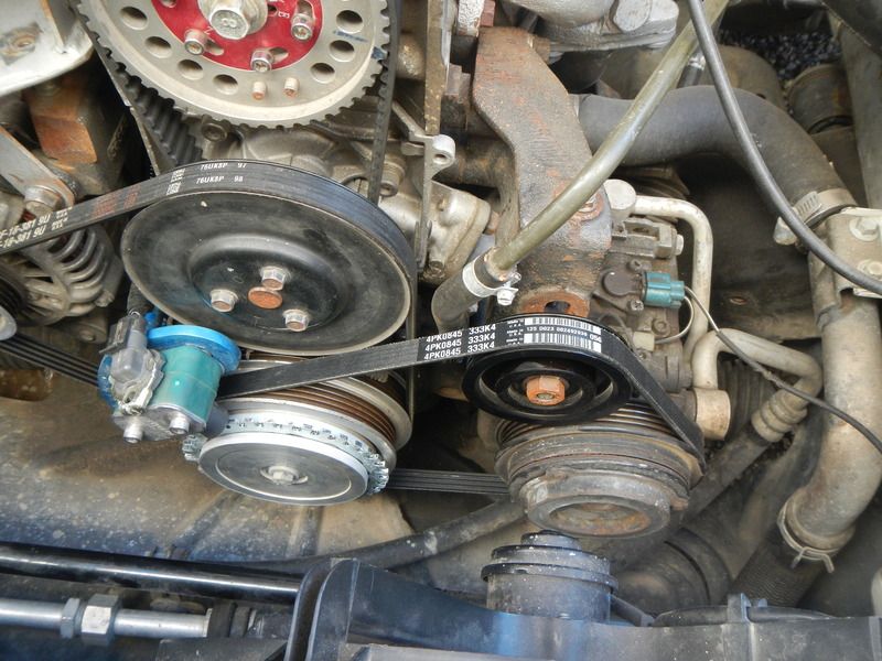
While we are looking at pictures, here is a shot of the power steering delete setup. I pulled the bracket off a Mazda 323 but a Ford Festiva or Aspire bracket would have worked. These parts would also work on the 1.6 and the 1.8 engine.

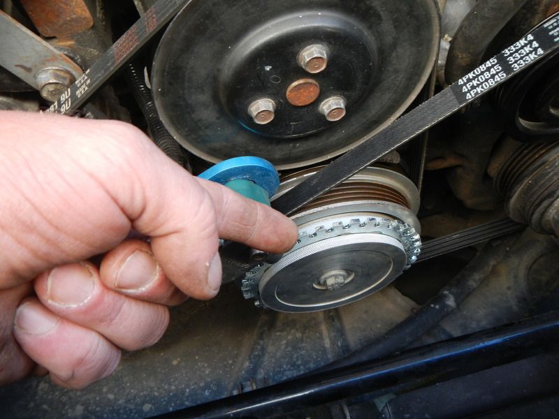
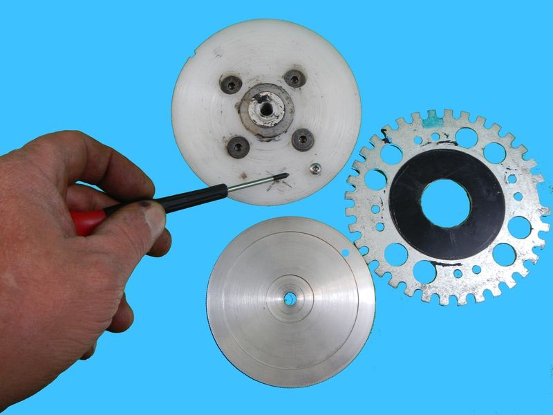
The only thing that kept the 36-1 crank wheel from slipping was friction...... So I drilled out a few parts and put a small screw in to keep the wheel from slipping again.

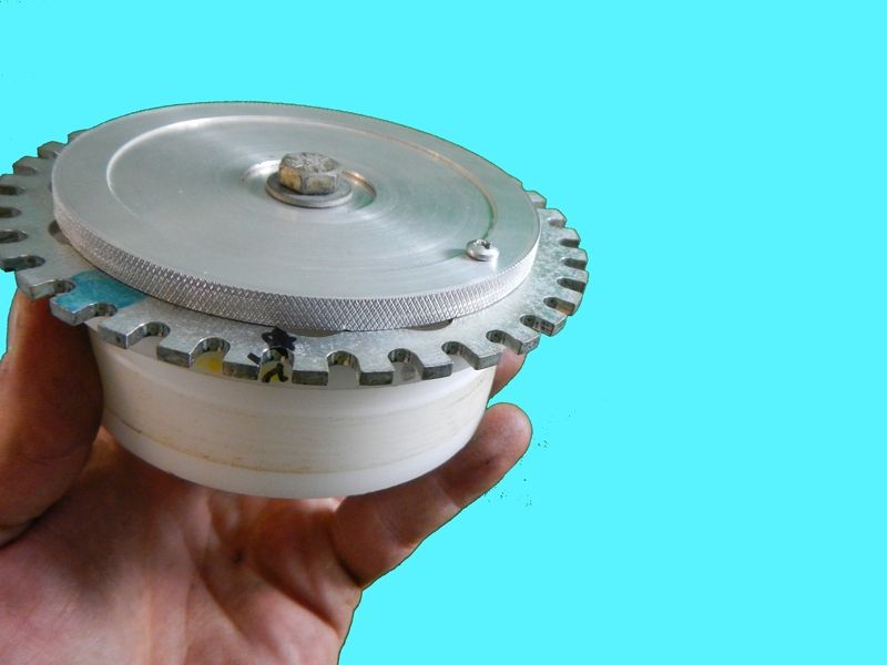
This is sort of how it all fits together, this time the little screw will keep the wheel from moving and upsetting the ignition timing.

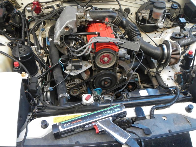
All back together and running again

Stay tuned!

1 ... 9 10 11 12 13

You'll need to log in to post.

Our Preferred Partners
e2siz1HnxQM4Qby2U3xrKGgw9NaILYAZjVGFdFY78XMK5ihxndlssZdq9wTFucRj