1 2 3
ShawneeCreek
ShawneeCreek GRM+ Memberand Reader
5/6/12 8:19 p.m.

So I had the interesting pleasure today of using the racecar to tow the pickup truck home (Oh the irony!). The truck made a loud clunk and the engine immediately stopped and refused to turn over. My Dad suspected that the engine had dropped a valve so he called for a tow home. The strongest vehicle left in the family fleet was the BMW; everything else has a 4-cylinder. We got the truck home and started to tear it apart. It turns out that the alternator had seized so much that it was able to stop the 350 Chevy in the truck and split the serpentine belt down the middle. Broken alternator:

Split belt:

In other news we sold the electric lock actuators from the car to a group in one of the Mechatronics classes at Trine. They used them as linear actuators in their machine to sort gobstoppers by color.

ShawneeCreek
ShawneeCreek GRM+ Memberand Reader
5/15/12 11:47 a.m.

During the autocross I soon tired of the very slow steering on the car (nearly 4 turns lock to lock). So I started keeping an eye out for an E36 to get a new steering rack from (they have 3.2 turns lock to lock). Well, a ’98 318i popped up at the Take-a-Part and I grabbed the rack for about $25. Brought it home and got to cleaning as it was covered in a literal layer of grime. Before:

After:

As part of converting an E30 to use an E36 steering rack the steering linkage in the engine bay needs to be shortened and clearance slightly and the tie-rods switched from the old rack to the new one. It’s not too difficult and there are lots of helpful how-to’s online. Shortened linkage: 

We got the rack put in last week with only a few small difficulties. Now all that is left is to adjust the toe back into spec. Next project is to gut the interior and start selling unneeded parts off on Craigslist.

ShawneeCreek
ShawneeCreek GRM+ Memberand Reader
6/16/12 6:55 a.m.

Long overdue update. Over the past couple of weeks I’ve been taking 3-4 hours after work each day to work on tearing down the car. First up was removing the interior. I removed everything but the front seats and dashboard. This created yet another pile of BMW parts in the garage. 

Next up was to remove unneeded wiring. To make this easier I removed the dashboard. I also eventually partially removed the HVAC box to remove the last bit of carpet and the remaining AC components.

The radio, speakers, electric locks, interior lights, check control system, and all of their related wires were removed and thrown into this bushel basket.

Any guesses at how much weight was removed in just the wires alone? (not including the components). After that I cleaned up all of the loose wiring and tucked it back into the channels and clips. Then the dashboard and other necessary components went in. Since I had removed the interior door panel I lost the handle to pull the door closed and quickly grew tired of grabbing the sharp edges of the door to close it. I got to looking at my pile of parts and I noticed the grab handles from the back seat. It turns out that with a leftover plastic nut they can be screwed to the door. It works well, and hey, it’s free. You can just see one in the picture below.

Next up the wideband O2 sensor gets installed. Then on to Mega-Squirt.

Chocoholic
Chocoholic GRM+ Memberand New Reader
6/18/12 4:05 p.m.

No guesses then.

Well we removed 7.6 pounds of wires.

AngryCorvair
AngryCorvair GRM+ Memberand PowerDork
6/19/12 8:56 a.m.

i guess 7.6 lbs. what do i win?

yamaha
yamaha Reader
6/19/12 10:11 a.m.
Chocoholic wrote: No guesses then. Well we removed 7.6 pounds of wires.

You answered before I saw the thread, I was going to say 11.5 though.

Quick question that may help you in the long run. Does the E30 have the tar based sound deadening on the floors like the E36? If so, a heat gun and paint scraper will help you lose 40-50lbs of weight. When we did the ti, there was 2 overflowing 5 gallon buckets of the stuff.

Chocoholic
Chocoholic GRM+ Memberand New Reader
6/19/12 3:54 p.m.

In reply to yamaha:

Yeah, there are patches of sound deadening around the car. you can see some of it in the last picture of the backseat; it's the brown stuff. There is also a 1" thick layer on the trunk floor rumored to weigh more than 30 lbs.

We had figured on trying the dry ice method before resorting to a heat gun.

ShawneeCreek
ShawneeCreek GRM+ Memberand Reader
10/20/12 9:35 a.m.

Wow, long time without an update. It seems that I’ve been busy. Let’s see if I can catch everyone up to the present.

I managed to sell the seats and sun visors from the car. After doing that I found a used race seat and 4-point harness on Craigslist. I’ve gotten the seat mounted to the car to make the easier to move around. The roll bar and harness will have to wait until after school is done with. While staring at the car one day I noticed how bad the grill looked. I had some satin black plastic paint lying around so I took some time and painted it up. It looks so much better. I also found a set of wheels on Craigslist. The tires were trashed so I got some nice new Khumos mounted up. This is basically how the car sits now:

Now the original plan for this car was to redesign the suspension as a senior project at Trine. Well, during the summer I was junkyarding for a turbo and stumbled upon this mounted to a Buick:

It’s an Eaton M62 supercharger off of the 3800 engine in a ’95 Buick Park Avenue Ultra. I picked up the supercharger and the throttle body (with sensors) for $100. I figured that I could work on installing this next summer before the Challenge. Once the senior design group had been formed we decided to change plans a bit. The suspension was already good with the Bavarian Autosports lowering springs. So we decided to mount the supercharger on the car instead. Now our senior project includes mounting the supercharger, changing the ignition system to Ford EDIS-6, installing MegaSquirt, and designing a serpentine belt system.

First up we took the car to the dyno at CJ Racing Engines in Auburn to get baseline power numbers. Stock, the car should have 168 hp and 160 lb-ft of torque at the flywheel. We ended up with 129 hp and 128 lb-ft of torque at the wheels. Not bad for a 24 year old car with more than 200k miles. Next we opened the hood and started prototyping the location of the supercharger. We ended up taking out the entire intake system up to the head. What we plan on doing is mounting the supercharger with the exhaust surface vertical and pointed towards the engine. We’ll build an intake manifold to support the supercharger and mount the fuel injectors. The intake will be in about the stock location, then go through the Buick throttle body, then loop around to the supercharger intake. Here’s about where we want to put it:

It will actually be mounted lower than this. The oil dipstick is currently in the way. This should be fun. We’re hoping for more than 200 hp at the wheels; 250 would be even better. This is where we are now. I’ll try and keep this updated more often. We welcome any helpful suggestions as this is the first time that we’ve done anything like this.

Jerry From LA
Jerry From LA Dork
10/21/12 12:03 a.m.

How does the blower get lubrication? Does it have its own built in reservoir or does the lubrication come from the crankcase? The orientation could be a concern lubrication-wise should you decided to mount it sideways as in the pic above.

JohnyHachi6
JohnyHachi6 HalfDork
10/21/12 2:59 a.m.

It should have it's own reservoir in the snout. I think that it's pretty much filled with oil so the orientation may not be a concern. Would be good to double check though.

Good luck with the supercharger install, sounds like fun.

Chocoholic
Chocoholic GRM+ Memberand New Reader
10/21/12 11:30 a.m.

Yes, the blower has a fluid reservoir in the snout. We'll be replacing the coupler in the snout, so we can check fluid levels then.

Jerry From LA
Jerry From LA Dork
10/22/12 11:03 a.m.

Of course, it also depends on the fill plug orientation as well.

ShawneeCreek
ShawneeCreek GRM+ Memberand Reader
10/25/12 7:48 p.m.

We made some more progress. We rebuilt the supercharger today because the coupler in the snout had a large amount of play. While everything was apart we thoroughly cleaned the 190,000 miles of gunk that had accumulated while it was in the Buick. You can see that here:

All shiny and clean:

The rotors didn't look too bad after cleaning. Obviously they are a little worn and the Teflon coating is coming off in places, but not bad:

All bolted back together and filled with fluid: 

4cylndrfury
4cylndrfury UltimaDork
10/26/12 8:49 a.m.

Awesome progress...considering those blowers are relatively easy to find, Id make sure to document the manifold design, and overall installation...Would be a great how to - lots of those bimmers, and lots of those blowers may even mean a kit w/ instructions could be a neat little side business...

Either way, very much looking forward to the next round of updates...

ShawneeCreek
ShawneeCreek GRM+ Memberand Reader
1/9/13 2:06 p.m.

Some more progress was made recently. The engine wiring harness was labeled and removed from the car. We simplified it by removing the diagnostic connector and wiring for things that are no longer there. We also added in wiring for the new sensors that didn’t exist in originally (MAF, stepper IAC, etc…). To make things simpler, a new wiring harness diagram was created to account for the numerous splices and changes. The diagram also has the wiring from Megasquirt to the BMW ECU connector and connector locations and pin numbers.

ECU wiring in progress:

Completed:

Engine harness in progress:

Completed: (other than wiring on a few sensors after their locations are determined)

I’m not really a fan of wiring, but I’m much less scared of it now. It’s best to take it slow and double check everything before soldering wires together.

Nashco
Nashco UltraDork
1/9/13 7:24 p.m.
Chocoholic wrote: I’m not really a fan of wiring, but I’m much less scared of it now. It’s best to take it slow and double check everything before soldering wires together.

Did you already get it running?!? If not, I would knock on wood if I were you. Wiring is pretty easy, when you do it right. When something is wrong, it can be a real bugger to figure out sometimes, and if it fried something in the meantime it's even more frustrating. I'm not scared of wiring, but I certainly respect it.

Bryce

irish44j
irish44j UltraDork
1/9/13 8:03 p.m.
Chocoholic wrote: No guesses then. Well we removed 7.6 pounds of wires.

I did the same thing to the rallycross car, except that "basket" included the cruise control stuff, the four window motors (changed to hand-crank), and all the lock actuators. Total weight of all THAT stuff, IIRC, was in the neighborhood of 50lbs!

phenryiv1
phenryiv1 New Reader
1/15/13 9:43 a.m.

I am with Irish44j. I have not updated my GRM thread in MONTHS, btu I removed about 50 lb. of deadening between the trunk and the floorboard, and that is not counting the carpet jute and other interior weight.

I am about to pull the dash to remove all of that wiring that I don't need, but I plan to keep my power windows...for now.

The only risk with removing all of the trunk weight is that it does unbalance the car a bit, particularly in the 325 models (unlike Josh's 4-cyl). I have found that I might need to add the spare tire back into the trunk to increase traction slightly. YEMV.

As for that grab handle on the doors, the roof handles will actually screw directly into the 2 OEM handle locations and have a more natural angle than what yours has. If you look at your door there is another plastic insert up near the power window controls- use that mounting point.

ShawneeCreek
ShawneeCreek GRM+ Memberand Reader
1/18/15 1:27 p.m.

Let's bring this back from the dead (I mean really, really dead, just over two years. I had to go to page 31 to find it). As happens to many of us, life gets busy and the project car gets sidelined. Since my last post I've graduated with my bachelor's in mechanical engineering, gotten married, moved three times, bought a house, started my career as a product development engineer at a tire company, and adopted two kittens from the local humane society.

I've been away from the forum for a while, but I spent the past few days reading Tuna's epic build thread for his truck. I came to the realization that if I had time to read the thread then I had time to work on the car a little at a time each day. I'm starting by getting this thread back up to date. So thank you for the motivation Tuna. Enough with the excuses. Let's get caught back up to the present.

When we left off I had a cleaned supercharger, a customized engine wiring harness, and a MegaSquirt ECU. I'll start with the intake manifold. Based on some calculations I determined that we needed an intercooler to prevent detonation. Mainly because we weren't changing the engine internals. As a reminder, here's the room that we're working with (the radiator is removed here):

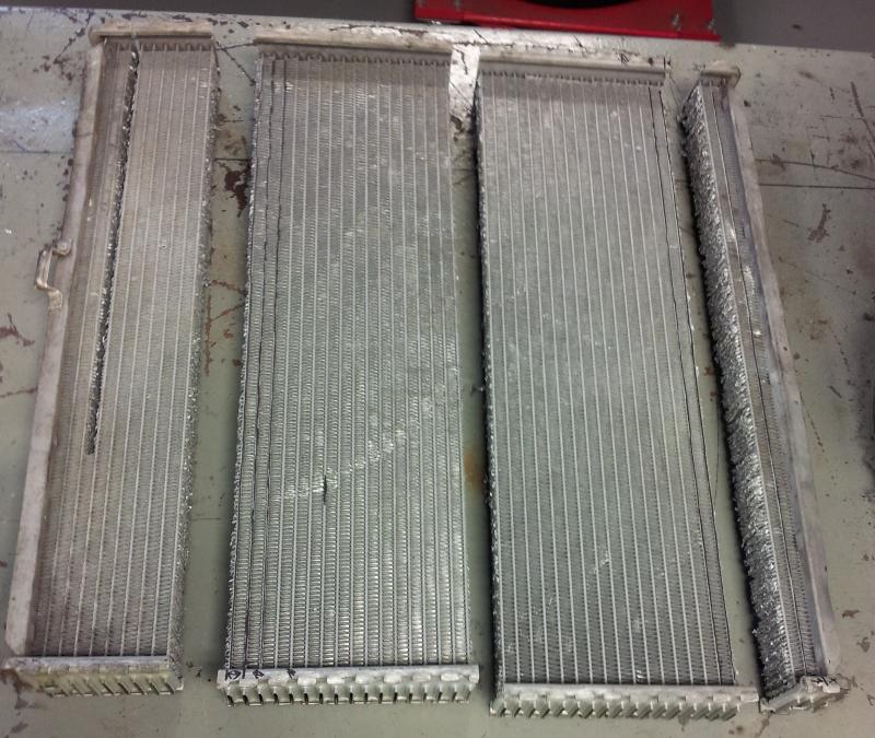
Not a lot of room. An air-to-air intercooler is out of the question. So air-to-water then. But I've got to do this on a Challenge budget. Off to the junkyard! There I found an aluminum radiator of appropriate width on a BMW 5-series. Next I cut two sections out of it. One to cool the air in the intake manifold and the other to cool the water back down.

So the idea is to build a new intake manifold that mounts to the head, has the fuel injectors, contains the intercooler, and has the supercharger mounted to it. The way we decided to do this was to salvage the part of the original intake manifold that mounts to the head and has the fuel rail and injectors then build off that. Pictures will explain it better. Salvaged part of original manifold tacked to the beginnings of the box:

Other side:

And now with the radiator core / intercooler mocked in:

Unfortunately, I made the classic engineering mistake of designing something that I couldn't build. The majority of the box is 3/8" aluminum (in retrospect, probably too thick) and the school's TIG welder was only rated for 3/16". Head, meet desk. Desk, meet head. Seeing as the semester was rapidly coming to a close we decided to move forward with what we had. Thankfully, the school has connections with a local company that does industrial welding. We got it done for free and they did an excellent job. It took 9 hours to do. I'll talk about how that killed my budget later :( Anyways, pictures of beautiful TIG welding:

Mocked up:

Next I'll sidestep back to the intercooler system.

unevolved
unevolved SuperDork
1/18/15 2:44 p.m.

Holy hell, 3/8" wall manifold?

Glad to see you're making progress. Where'd you get so much aluminum?

ShawneeCreek
ShawneeCreek GRM+ Memberand Reader
1/19/15 4:47 p.m.

Yeah, 3/8". I was worried about supporting the 26lbs of supercharger nearly a foot off the the engine head, along with the internal boost pressure. So I made a mildly educated estimation with some safety factor thrown in. I got the aluminum from a local Metal Supermarket. You can order the metal rough cut to any size. Intercooler system: First up, the front intercooler to go in front of the radiator and cool the liquid back down. We used the second section of the junkyard radiator and had end tanks welded to it.

Then we made up some brackets and mounted it in front if the radiator. Done. According to the calculations that I'd done earlier I knew that we needed a volumetric flow rate (of the cooling liquid) greater than about 5 gallons per minute. So I needed a pump designed for liquid, fairly powerful, capable of running on the car's 12V power system, and of course, cheap. It took me a while, but I finally had a light bulb moment: bilge pump! I stopped at the local boat shop and picked one up. It meets all of the requirements: powerful (nobody wants their boat to sink) and designed to pump water using the boat's 12V system. Then we did a quick test with a bucket of water, a stopwatch, and the components of the cooling system to ensure we got the flow rate that we needed. Sorry, no pictures. Now we need a reservoir to put the pump in and to increase the fluid capacity of the intercooler system. Again, it needed to be cheap, but also watertight. After a little thought we came up with this:

6" PVC pipe with a couple of caps. An inlet and outlet port, the pump inside, and the wires running through the cap. One of my teammates noticed that it looked like a crude version of a pipe bomb. Oops, can't have that on campus. A quick coat of paint later it looked friendlier. Then we strapped it to the passenger floor and wired the pump to a switch on the dashboard: 

We got some 1" diameter tubing and plumbed the system. The hoses run through the firewall where the A/C lines used to. Perfectly sized and there was already a grommet there. Next up, the pulley system.

solfly
solfly Reader
1/20/15 10:36 a.m.

following, love the ingenuity

echoechoecho
echoechoecho New Reader
1/20/15 11:43 a.m.

look at the prius inverter coolant pump, cheap and pumps about 6gpm. Its a nice little pump and has mounting holes already.

conesare2seconds
conesare2seconds HalfDork
1/20/15 12:07 p.m.

Nice to see this thread going again.

ShawneeCreek
ShawneeCreek GRM+ Memberand Reader
1/20/15 4:51 p.m.

I think the bilge pump we have should work well. It's rated for 1,000 gph (16.7 gpm). I think we ended up with something in the range of 10-12 gpm when we tested it with our system. The Prius pump isn't a bad idea, though. Pulley system: Stock, the BMW has an accessory V-belt system. One belt for the water pump and alternator, one for the power steering pump, and one for the A/C compressor. But the supercharger was designed to run on a grooved serpentine belt. I'd already tossed the A/C system, so no worries there. I wanted to keep the power steering if at all possible. And of course I need the water pump and alternator. Just to make things even more interesting the back of the crankshaft pulley has the trigger wheel integrated into it.

Interestingly, the crank pulley is actually two-piece. The outer two V-belt grooves (A/C and power steering) are separate from the inner V-belt groove (water pump and alternator) and trigger wheel. Hmmm.... I wanted to use a serpentine belt to run the supercharger because I knew that it should work without slipping. But there's not enough room between the engine and radiator to run the two inner V-belts and a serpentine belt. Solution: custom outer crankshaft pulley and power steering pulley, both with serpentine belt grooves. Many measurements and CAD designs later we got the two pulleys made in the rapid-prototyping machine at school. Mocked up:

Not bad. It needed a few tweaks but it was close. I ordered up two chunks of round bullet aluminum and started talking to the DET (design engineering technology) department. They have a very high tech CNC mill and, more importantly, a CNC lathe. The professor was very helpful and taught me G-code, which is CNC programming language. It's cool stuff. Yes, I'm a nerd. Machining in progress:

Completed pulleys:

vs stock pulleys:

 Now that we had the pulleys and test fit them we needed to anodize them. I researched how to do it at home. It involves battery acid and a battery charger. In progress:

Then, since they were anodized couldn't pass up the chance to color them. Water, Rit laundry dye, and a little heat:

Oooh, shiny!

Next I’ll finish up the intake system.

1 2 3

You'll need to log in to post.

Our Preferred Partners
mOK2O7DmEeqZkhkDVyAWH7QKN94LK6dOwB1PFKikP61TiOqBkKTeGicSipT9CsbX