


I'm not sure my car quite falls under the "everyday second hand sports car" description ![]()
But that's just a function of the owners, not the cars. Just think of what we've seen done to things like Geo Metros around here.

I'm not sure my car quite falls under the "everyday second hand sports car" description ![]()
But that's just a function of the owners, not the cars. Just think of what we've seen done to things like Geo Metros around here.

In reply to Keith Tanner :
I mean no disrespect to your Miata, as I know it is a far cry from the average example.

Productizing would probably take all the fun out of it, and be a pita to boot.
IMO open-source the software and sell or package enough hardware that someone can get going with it in a miata and I bet it'd take off with other applications as well.
The hard part for people to DIY would be the gauge faces, I think. Everything else is readily available off the shelf. If I were looking for a cottage business, it might be fun. But it wouldn't work at FM, which isn't set up for "just like that but with reverse rotation and a 8000 rpm redline and my name on the bottom".
When it's good enough, I probably will publish the code.
Excellent - see you on GitHub :)
It would be rude of me not to do so given how much time I spend learning from others.
As promised, here are moving pictures. I seriously didn't do a great job on this, I apologize for the rambling. Also, my RPM-sensitive colors on the tach face went away which led to lots of questions about shift lights. Argh.
Slipping needles: the OD of the shaft on my Miata speedo is 1.01mm. The OD of the stepper is 0.96. The OD of the tach is 0.71mm. So it's clear why the speedo needles were a loose fit and the tach wouldn't go. I could get GM needles (some are now on the way), but I realized while talking to someone that I could probably heat up the plastic and do a nice press fit with the tach needles.
Success. A nice fit.

Reassembled, powered on and ran through some of my tests. Much, much better. Not perfect. The steppers are skipping slightly, I think when asked to do an immediate change of direction at maximum speed while doing their calibration sweep. But I can fix that in code. I am much happier - although I'll be happier yet when I get my tach colors right and move the LEDs to the correct locations.
Progress!
I haven't been focusing on this too much because I got distracted with building a super brake kit for the Miata, but I did spend a bit of time on it today. And got frustrated with the steppers almost immediately. So I figured what the heck, in theory the "air core" gauges that come on the car should be simple to implement.
Air core gauges are basically voltmeters. You feed them one voltage for the sine of the angle you want and another for the cosine. None of this tedious step-step-step stuff, it will WHAP to the new angle with a single simple command and sit there waiting for more. So the programming is easy.
(nerding)
The motor control hat I'm using can run DC motors or steppers. And DC motors usually use PWM control to manage speed, which is effectively like controlling voltage. Basically, I just need to treat the air core as two DC motors. The software that controls the DC motors uses a throttle range of 0-1. Actually, -1 to 1 because they have reverse. And very conveniently, if you were paying attention in high school trig, you may remember that the results of sine and cosine are in a -1 to 1 range. Super-easy. I wired up a gauge that way and...nothing. Then I hooked up the power to the gauge (oops) and WHAP, it worked.
That should speed up the response of the cluster pretty nicely and clean up a bunch of code. Plus I already have all sorts of air core gauges sitting around from all of the clusters I've taken apart. I'm sure I'll need steppers for something at some point, but not this. Victory!
Progress report: I'm spending a lot of time sitting and staring at this.
I have the air core gauges in place and some regret that I spent as long as I did on the steppers :) But hey, I learned stuff. Installation involved cutting and painting some new gauge faces because of different mounting holes.
Now I'm starting to think about how to "de-prototype" this. Not turn it into a polished product, but to make it a little cleaner and vibration-proof. That means mounting solutions, soldered wires or proper connectors and code that will let it power on/off properly in a car. I have a few ideas about the latter but I may just have it completely power off when the ignition is turned off for now. Depends on boot time. I also need to come up with a bracket for the accelerometer and the stack of electronics. This is requiring a lot of thinking about ideas - I have the accelerometer mount figured, but the electronic stack is going to be a big ugly box. I'd like to have this installed and driving around within a couple of weeks. I could do it today but there would be many zipties involved :) Might still be a good idea for testing when I think about it.
Current wish list:
- dimming with headlights
- high beam indicator
- clean shutdown
- MIL indicator (I may have already done this when I think about it)
- maybe a way to put light on the gauge faces, but that is a low priority for my particular use case
I've already added a threshold so the friction circle indicator isn't constantly jittering around.
And because moving pictures are more fun than a wall of text, here's my demo program running on the air cores. The sweep at the beginning is pointless but it really shows the difference in speed. At the time I shot this, I had a little bit of binding on the speedo so it wouldn't relax to zero. That has now been fixed. I still have a little calibration to do on a couple of things but that's just details right now.

Really interesting. Why in the world did OEMs move away from air core motors to steppers? I can only guess there's a cost savings involved.
I'm not sure a lot of them did. And I have a report that current Corvettes use air-core gauges. So, umm, I've got nothin'.
There is a very good chance you will have the option to buy something like this in the future. I'm working with a Miata enthusiast at an electronics company to make this happen. The first prototype of the production version is coming together. The goal is basically "OEM+", adding the LED light capabilities to a factory cluster and responding to the inputs that are present in the factory cluster. It will have a defined set of options so you can configure it to suit your needs without the amount of programming I've done. And I've requested that it also have a UF2 bootloader setup on board so you can load in CircuitPython and take full control for a DIY implementation. It will also be able to use stock-style gauge face overlays so you can get custom gauges with Pokemon on them or a 4500 rpm redline in case you've done a VW TDI swap.
Figure six months to reach market. I'm pretty jazzed. I'm going to have to come up with some extra capabilities to justify the overpowered Pi running my own version. Maybe I datalog everything and have it magically upload the logs to a server when I park in the garage. Or an integrated dash cam.

In reply to Keith Tanner :
Thought about using the Raspberry Pi Pico instead?
In reply to RossD :
I'm not sure it would bring anything to the table. My biggest concern about the Pi is dealing with boot and shutdown. The Pico is cheap but doesn't address the limitations if I understand it. Power consumption is not a problem for me, I have a 500 hp generator :)
A friend just pointed out that Adafruit has an M4 Feather with built-in CAN. They also offer a motor hat in the Feather form factor. Since it runs a Python variant, I should be able to port my code over without much effort at all. That will probably allow me to use more efficient code for my LED (no more conflict with the CAN board) and will get rid of the startup/shutdown factor. Basically, the general Pi was good for development and the next step is to use a more specialized microcontroller. It'll help with packaging in several ways, so the current plan is to strap the current pile of wires into the car and do some road testing, then when the M4 I just ordered gets here I'll switch to that platform and see how it works.
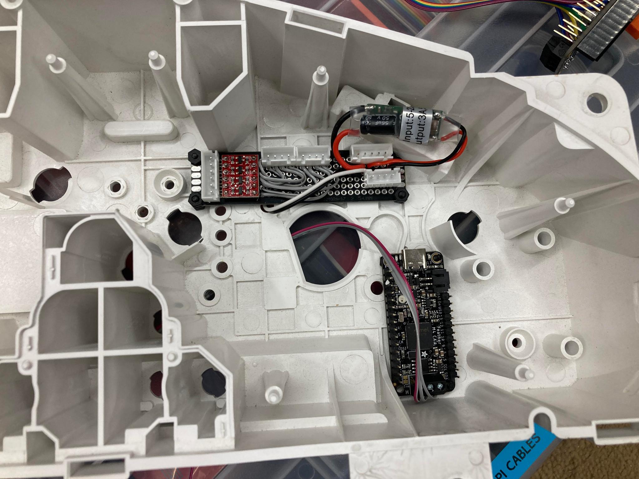
Spent some pleasant hours this weekend playing with the programming. I now have a headlight indicator - green for lights, blue for high beams - and dimming when the lights are on. I also cleaned up some code and spent time thinking about packaging...
...until I realized that with the little Feather setup, I can probably put everything inside the stock cluster. Not possible with the Pi but the Feather is considerably more compact. Nice little side effect. I'll probably be able to get everything I need from the cluster inputs other than the CAN and the accelerometer. So I'm not doing any more packaging work in that regard.
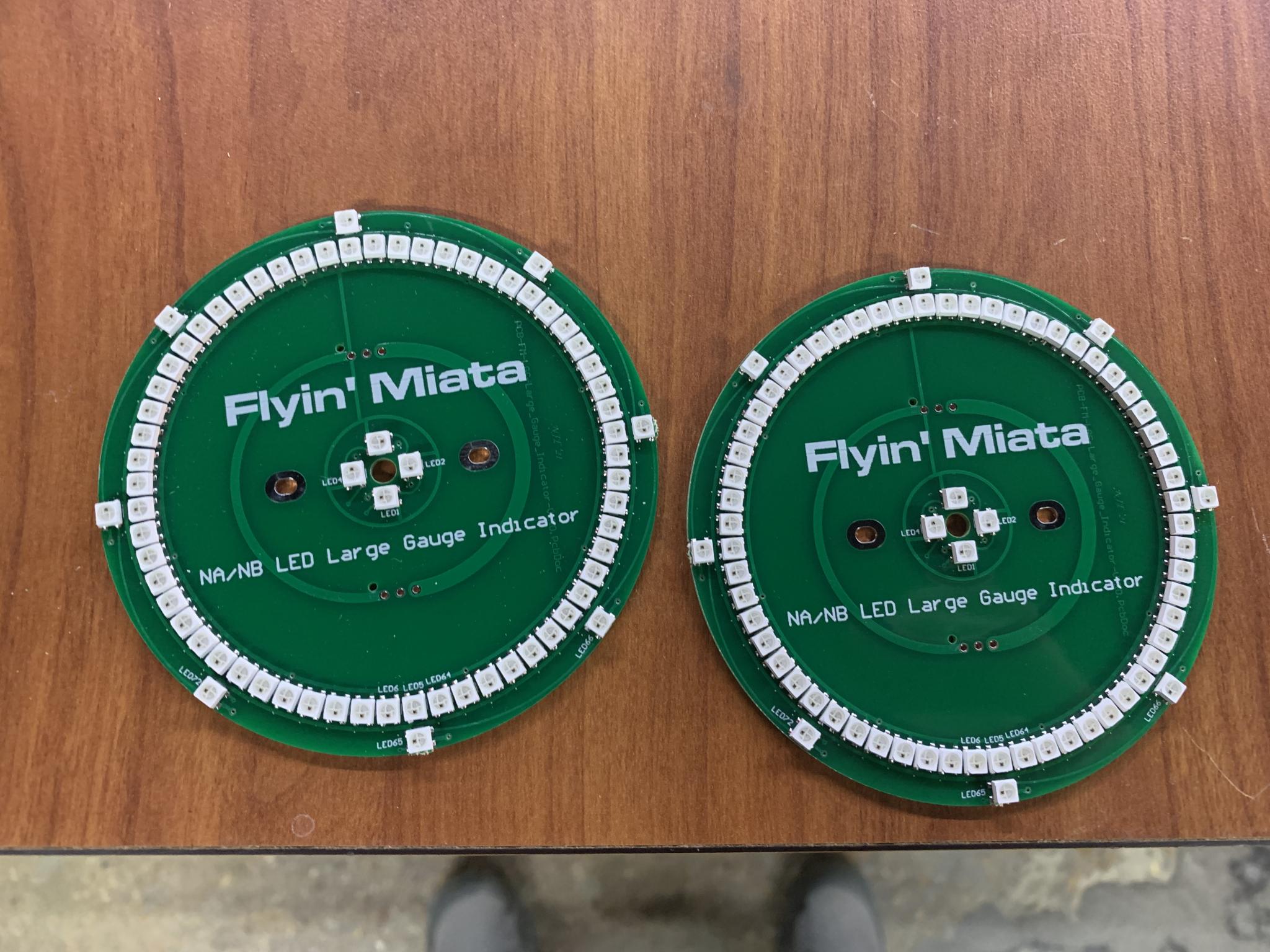
I may also see if I can code the two 60 LED rings as one array of 120 LEDs. I have some ideas on how to do that well, but the only real advantage is that it saves me a few wires. The LEDs may also respond faster but I'm already doing pretty well in that regard. So it's something I'll keep in my back pocket.
So I decided to work on mounting the accelerometer. Since I have a big fat roll bar tube as a dash support, that was the obvious place. A little 3D work and voila! I did print it the wrong way up but that's unlikely to be an issue.
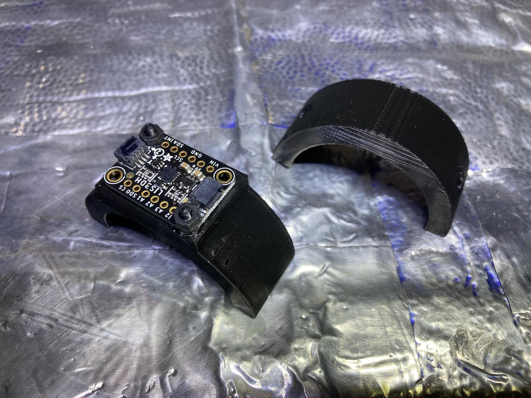
Threaded inserts! You stick these on a special soldering iron tip and they just smoosh right in to place. I think I'm in love.

In situ.

More details when the Feather gets here!

Very cool. Any chance of them producing a similar universal tach? I would love to run something like this in my build.

If you're going to comercialize this (and I think you should) you may want to look at a less hobbiest oriented microcontroller. The cost per part will be lower and you can get a version that complies with the ISO 16750 recomended temperature rating of -40C to +90C. You'll probably have to change to C or assembly for programming but it'll run faster without the interpreter overhead.
APEowner said:If you're going to comercialize this (and I think you should) you may want to look at a less hobbiest oriented microcontroller. The cost per part will be lower and you can get a version that complies with the ISO 16750 recomended temperature rating of -40C to +90C. You'll probably have to change to C or assembly for programming but it'll run faster without the interpreter overhead.
Did you see the post from a few days ago about the production version? The plan is for it to use an STM32F4 microcontroller (I didn't mention that at the time), that meets your temperature specs and is considerably less expensive. Really, I should have started with something like this from the start but I worked with what I had and knew and I learned a few things because of it. I'll tear the Pi down and it'll get used for other projects.
Turns out that cars run really slowly compared to computers :) A high frequency signal such as the tach is sent every 12.5 ms, which is 80 Hz. That's nothing.
bgkast, I don't know if we'll ever push this as far as a universal unit with the various packaging that requires. You could probably adapt one of the Miata-specific boards to other applications with some screwing around, but a standalone tach in a can? That's a different market and one we're not well suited to serve. We'll probably leave that to the gauge manufacturers like Autometer.
Keith Tanner said:APEowner said:If you're going to comercialize this (and I think you should) you may want to look at a less hobbiest oriented microcontroller. The cost per part will be lower and you can get a version that complies with the ISO 16750 recomended temperature rating of -40C to +90C. You'll probably have to change to C or assembly for programming but it'll run faster without the interpreter overhead.
Did you see the post from a few days ago about the production version? The plan is for it to use an STM32F4 microcontroller (I didn't mention that at the time), that meets your temperature specs and is considerably less expensive...
No, I did not. I should have known that you'd be on top of that. I also shouldn't post early in the AM before I've had coffee.
I can't take credit for the chip they chose, the electrical engineers are the adults in this particular situation :) Basically, my video caught the attention of a Miata nerd with a specific set of skills who is using this as an excuse to build a better one on company time. That's how a lot of FM's products came to be, honestly.
Update! It took forever for the new hardware to get here. Well, 10 days, but it was like the 10 days before Christmas when you're six. So yeah, foreeeeeever.
First impression: tiny.

This little guy runs CircuitPython and I did most of my programming in Python. They're awfully similar but the libraries (chunks of pre-written control code) are a bit different. Enough that I'm having to go through pretty much the whole thing. But the Feather boots immediately and has no problem with power up/power down so it's a better choice for this application no matter what. I did discover last night that CircuitPython has an existing library that makes controlling the LEDs ridiculously simple and a bunch of my custom code is no longer required. That's okay, I now know how to bit bang so it's a win.
The goal today is to get it working again, then package it up and install it. You know, everything. I'm starting with breadboarding all the wiring to make sure it worked. I spent several hours on it last night trying to figure out why the LEDs weren't working, gradually stripping off all the extra parts until I had the bare minimum. Still no work. I had new software and a new microprocessor and some different wiring and a new code library so it was difficult to troubleshoot. The only thing I was reusing was a logic level translator - it takes the 3.3v signals from the computer and bumps them up to the 5v the LEDs want to use. It's a simple thing. Finally, just because, I swapped out this one known part and the LEDs started working. Sheesh.
Fingers crossed I can get this done! I'm doing another Facebook Live video on the thing tomorrow at 2 pm Mountain if anyone wants to join in. Since I did the last one in March, I've changed the motors, changed the controller, cut new gauge faces, rewritten the software and rewired the LEDs.
My life right now...

Spent a bunch of time yesterday bringing everything back online. Some things ported over without a problem - the motor control was already using a CircuitPython library so I didn't have to touch it. But there were enough changes to other things such as the LEDs and the accelerometer hookup to keep me troubleshooting small problems for a while. A very enjoyable way to spend time if you have a certain type of mind. At the moment, it's almost back to where I was but slicker - but I haven't tried hooking up the CAN signal yet. Will it have a stroke when it sees an RPM signal? Maybe.
Turns out CircuitPython has a built-in library for controlling these LEDs that is ridiculously simple to use. Had I known about that, I could have saved myself quite a bit of work getting on top of that. But I'm glad I didn't, because I learned a lot doing it the hard way right down to building my messages via on-off-on binary.
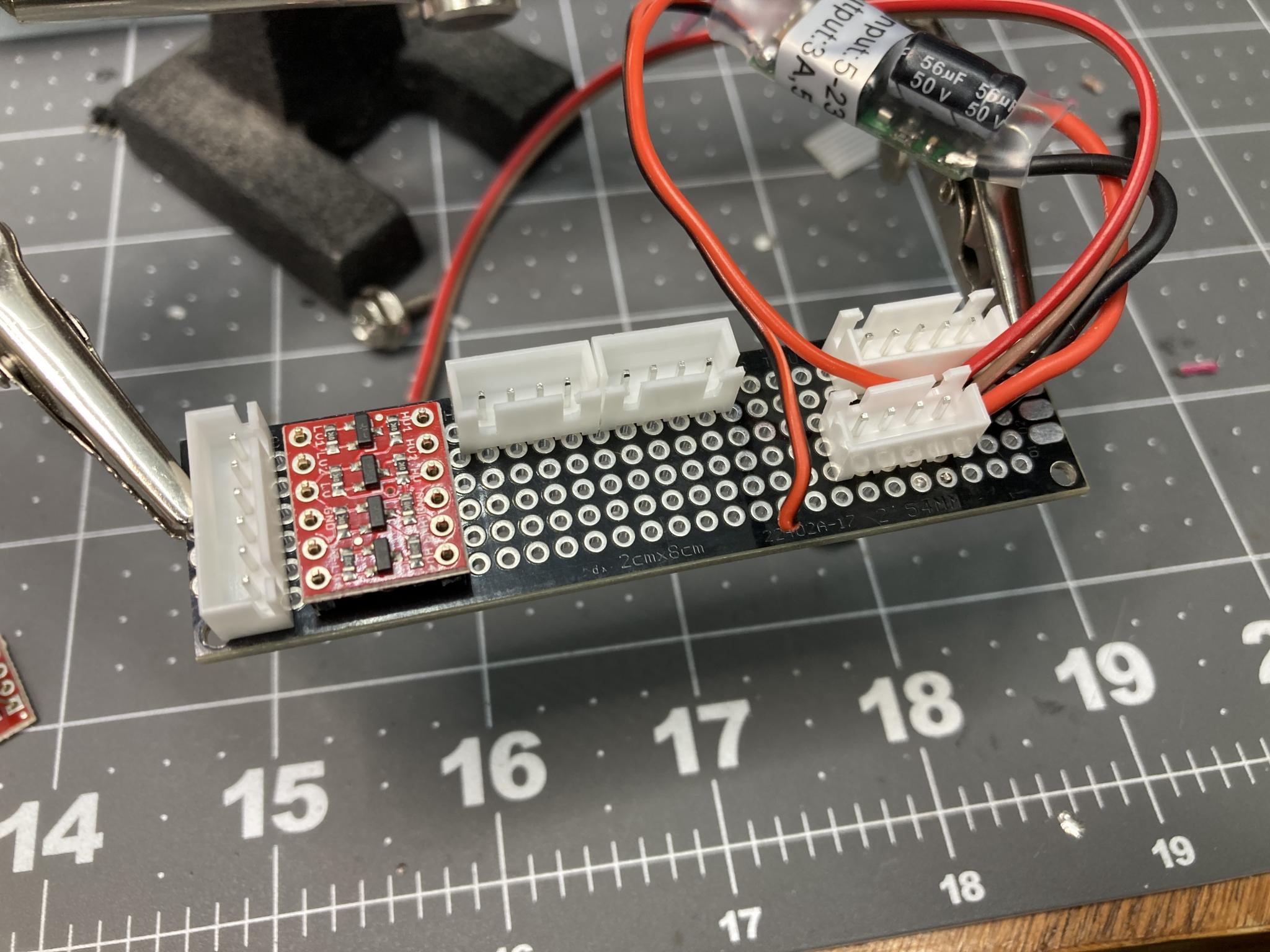
I was also trying to turn it from a very prototype setup to a semi-permanent one. I have a couple of small "breakout" boards that have little specialized chips on them, such as the logic level translator (turns 3.3v signals from the controller to 5v signals for the LEDs) and the optoisolator (turns the 12v car signals into 3.3v). In prototype mode, they're just floating around on the end of wire bundles. I decided to solder them on to a piece of circuit board and add proper latching connectors, which was a fun learning experience and fiddly.
This picture (no optoisolator yet) makes it look well organized.

But the reality is a little chunkier than I'd like. Those air core motors are fast but a bit bulky. I may have to alter the wire hookups. As it is, I can't quite get everything inside the cluster.

The rework from Python on a Pi to CircuitPython has also given me the opportunity to clean up the code somewhat. Not completely, but it's a little more portable now. I could also run this thing as Arduino (the Feather is bilingual in that regard) but that would pretty much be starting from scratch. As it is, this is a good version 1.1.
If I can manage to get this cluster packaged, I'm basically ready to get it in the car and get mobile. Everything is now powered from the cluster using some extremely convenient screw points that are ideal for hooking up with ring terminals. I just need to plug in the stock wire harness, the accelerometer and two wires to the CAN. I'll figure out the hookup to pull in the signals for headlights and high beam later. The Feather can also take analog inputs so I could potentially throw something in there for low fuel, although that's not a capability I am used to.
One big change with the Feather is the fact that it boots crazy fast and I no longer have to worry about shutting down the Pi cleanly. Here's a video that shows how quickly it wakes up after I plug it in (aka turn on the ignition). One of the power wires for the tach came off so you don't get a tach needle sweep, but as soon as that speedo responds it's alive.
Reminder: Facebook Live on this thing at 2:00 PM Mountain today via the Flyin' Miata FB page. I welcome questions - I'm probably going to be talking mostly about the production version and it would be a lot more fun as a conversation instead of a monologue. Questions and comments today will likely affect the final product.
The video went well although it suffered for me not building a show-off function that whipped needles around and made fancy colors. I'll post it here.
But I did get this in my email today. It's happening! My hacked-up dash will be obsolete. But I'll keep it :)
Veedeo! Watch the blinky lights and listen to the babbling.
We're getting a LOT of interest in this. Man, who knew that my weird little science experiment would get so much attention.
Comments/requests/questions at this point have a good chance of influencing the final product. This is important, the GRM community has seen far more of this thing than anyone else and I have a lot respect for the minds here - so c'mon, give feedback!
While we go back and forth on the spec sheet for the final version and figure out how the heck to backlight it, I've kept working on my own to see if I can get it into a car. That means more packaging work. I picked up a number of these "protoboards" a while back - they don't have any connections between the holes, so you just have to blob solder around. But it's a way to make a circuit board without all the messing around with actually making a circuit board. First, I worked on layout. Good thing these boards and connectors are cheap, I ended up starting over a few times after I had a better idea after starting in with the soldering iron.
Much better. I can close up the cluster with this! The boards are anchored with small nylon M2.5 screws.
I'll spend some more time troubleshooting and checking things out tonight and hopefully have it in a car soon! I'll put the optoisolator on a different board, that's a lower priority.
You'll need to log in to post.


