
https://youtu.be/vpEV_uX1zf8
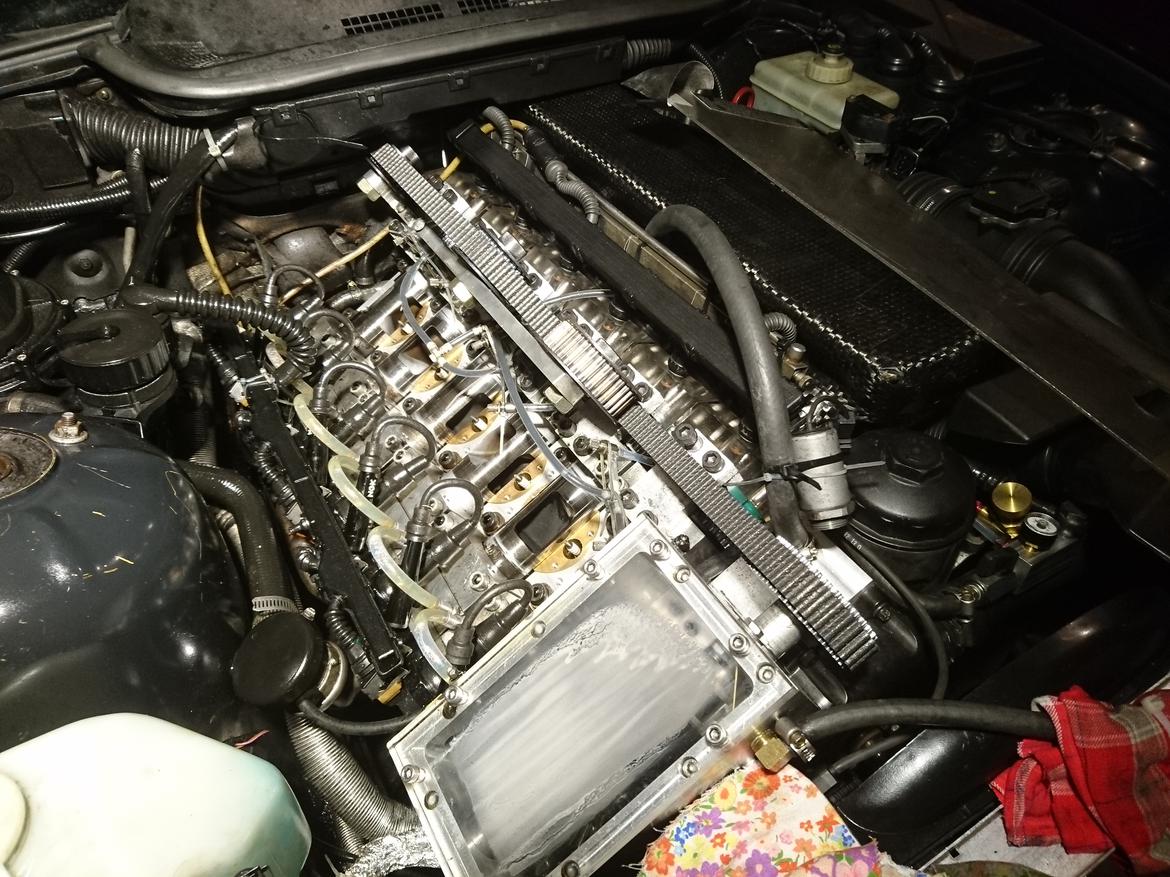
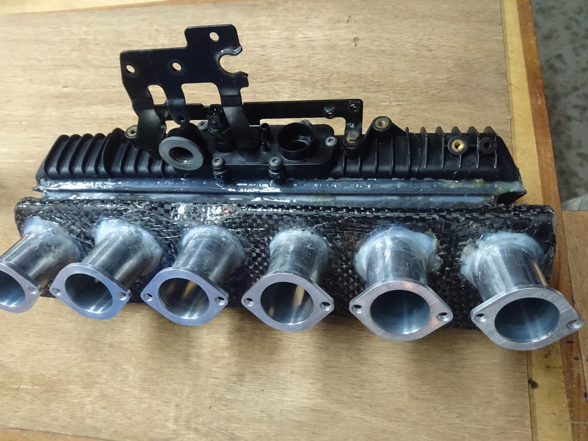
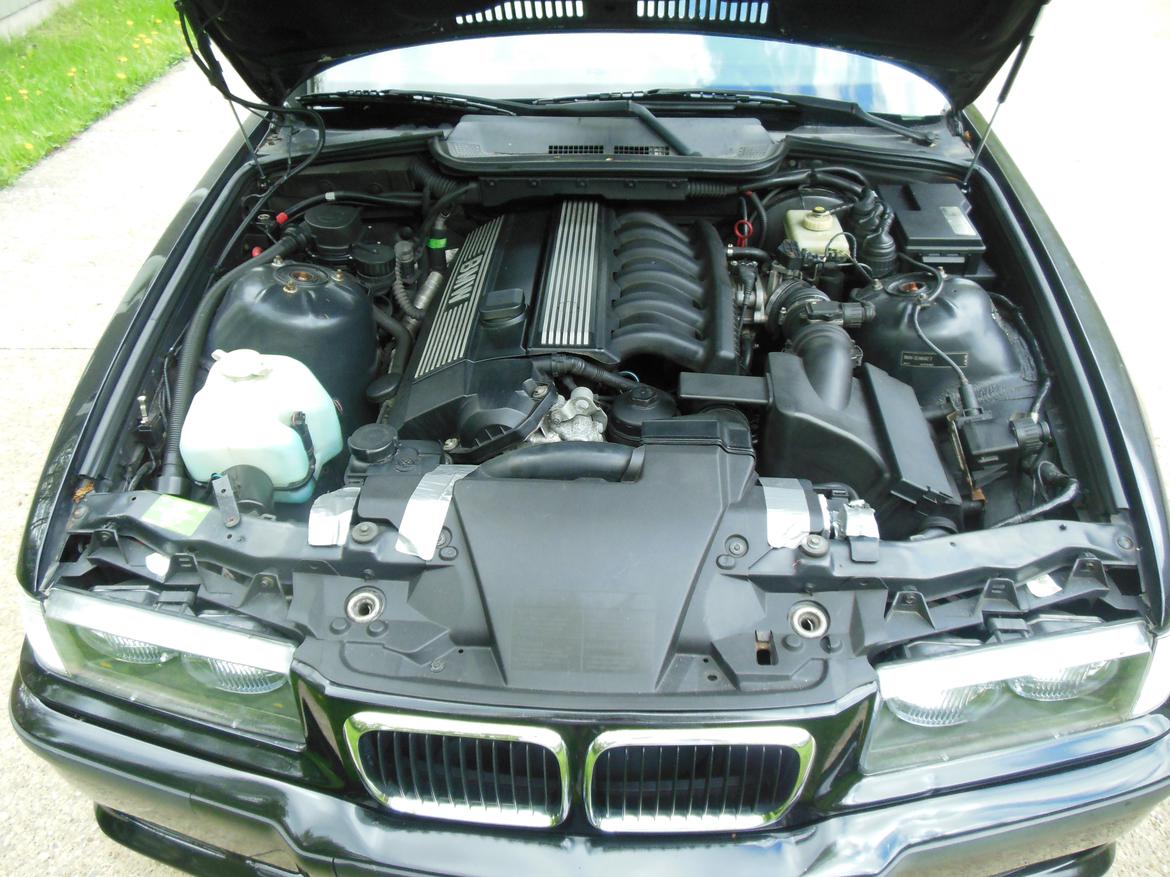
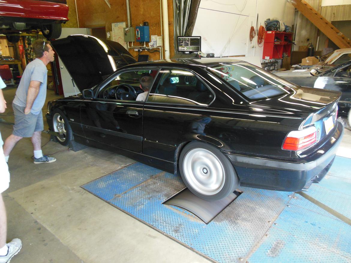
This is my explanation video of the rotary valve engine head that myself and my brother have designed from scratch, machined many of the components ourselves, assembled, trouble-shooted, tuned and improved over the last three years. The car is a 1999 BMW 328iS with a 5 speed manual with 163k miles on the 2.8L inline 6. We dyno tested the engine before hand and plan on re-testing it in the near future. We purchased the car in April of 2015 and one year later, we had a running rotary valve engine in it after spending about 5 months backwards engineering the interfaces of the stock cylinder head, 6 months of machining parts (over 700 pcs in total) and a month to assemble it in the car and make it run. The head is fully integrated into the car, utilizing the stock exhaust(ported and polished), stock ECU and sensors, and is grafted into the original intake manifold with 6 velocity stacks and a custom carbon fiber intake plenum.
There are many Youtube videos of it on my channel: Mrpizzaman09. Else, you can search for rotary valve engines.
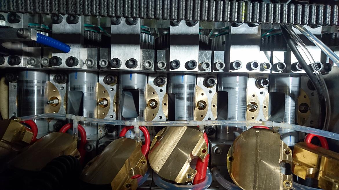
This is a photo of it while it still had the double sided belt for the valve train.
I'll try and post for details and photos in the next couple of days.
This is the first modern production car that I'm aware of with the axial flow rotary valve design, and the first inline 6 version that I've ever seen, particularly with 6 individual valves.
If you have any questions, I would be more than happy to answer them.

759NRNG
SuperDork
9/29/18 8:19 a.m.
You're utilizing the bronze shaft bearings also?
Oh and wow also.....
Hey I know you! Welcome to GRM, where frankenstein engines and cars are truly admired and fatally enabled. Sounds like it's running great! Can't wait to see dyno results!
Incredible!
When do you guys plan on taking it to the dyno?
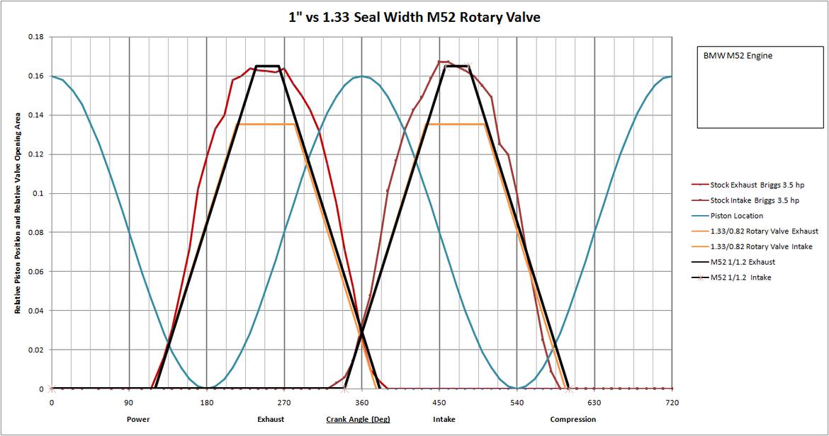
The goal of the project aside from proving you could make an engine with this design, was to increase the power to be equivalent to a Euro M3 from a hp/L standpoint. With no poppet valves in the way, the air can flow much more freely into the cylinder, especially at high speeds. The valve timing on this engine is super aggressive, likely equivalent to 250-260 degrees of duration at 0.050" of a normal cam.
More pictures!
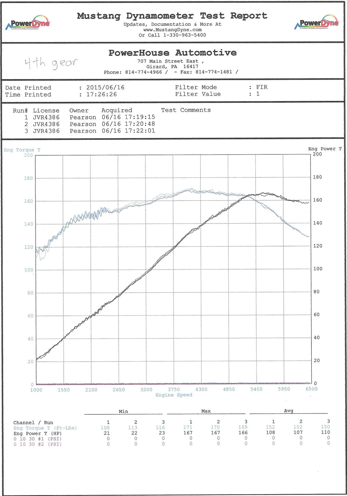
Stock dyno graph
I need to get some of the photos from this year off of my phone to show the latest changes and pictures of the valve and floating seals.
I believe the whole cylinder head could be bolted straight to an E36 M3 block and would work quite well. It has upgraded 24lb injectors and I have the tuning software to change all of the tables in the ECU.
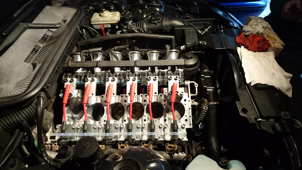
Here's an older photo, but it shows the valves really nicely.
You guys are nuts in the best way. Keep it up. And as Feiburger said "If it works it's not dumb."
I don’t know wtf i’m looking at but i’m pretty sure it’s awesome
759NRNG
SuperDork
9/29/18 12:44 p.m.
What is the weight differential between this arrangement and the stock cylinder head?
759NRNG said:
What is the weight differential between this arrangement and the stock cylinder head?
It's about the same. We didn't really try to optimize for weight, so I'm sure you could cut 20-30 lbs out of it. The car weighs about 3050 lbs.
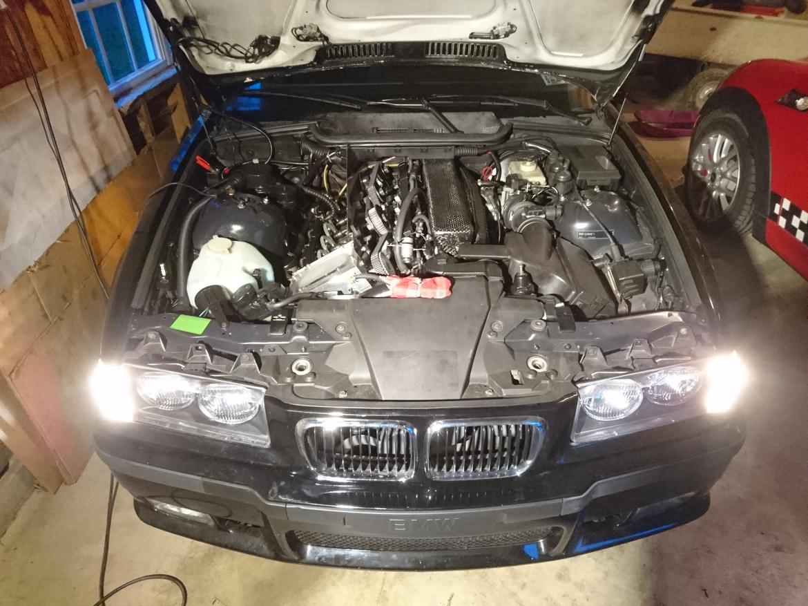
The car is about as close as you can get to an M3 without actually being one from the factory. It has the upgraded suspension package, M visual package and some of my favorite wheels.
We have about 60 miles on it so far and probably ~100 hours of run time.
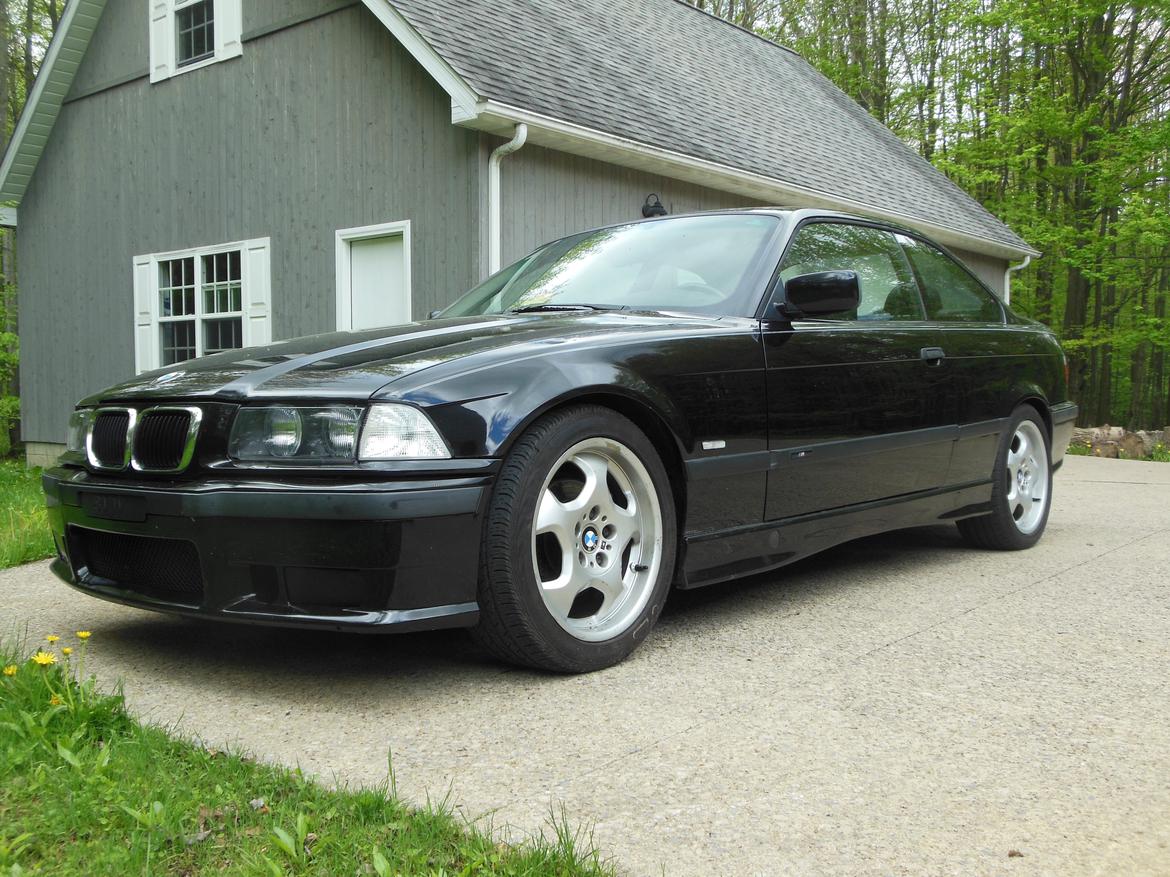
This is how it started off.
Judging by the date that's a stock dyno chart for this car? I'm really interested to see MPG figures and the torque curve on this car.
Slippery said:
Incredible!
When do you guys plan on taking it to the dyno?
Hopefully in the next few weeks. Today we are working on the cooling system a bit to fix some leaks, but otherwise it's ready to go. It will be fun to adjust the relative valve timing and see how it reacts on the dyno.
https://youtu.be/_3egpax5sZI
This project is absolutely incredible. It is great to see someone do something so outside the box.
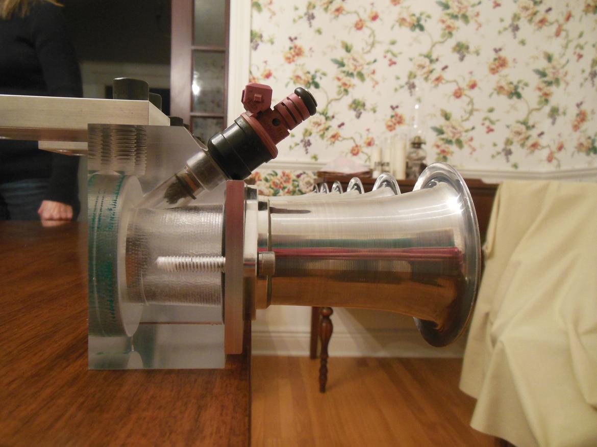
Some photos from when we machined the parts. The clear blocks for the injectors are awesome since you can sometimes see flames from any backfiring and sometimes the fuel being sprayed in.
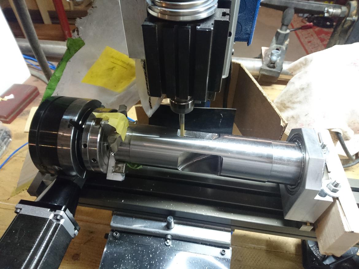
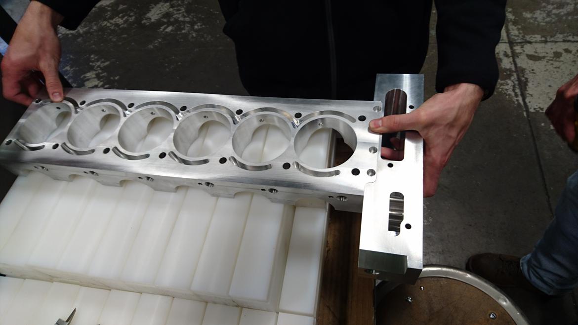
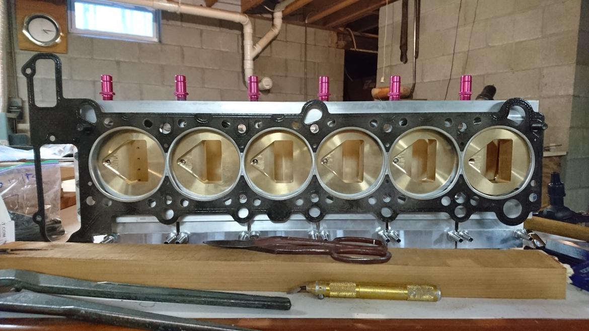
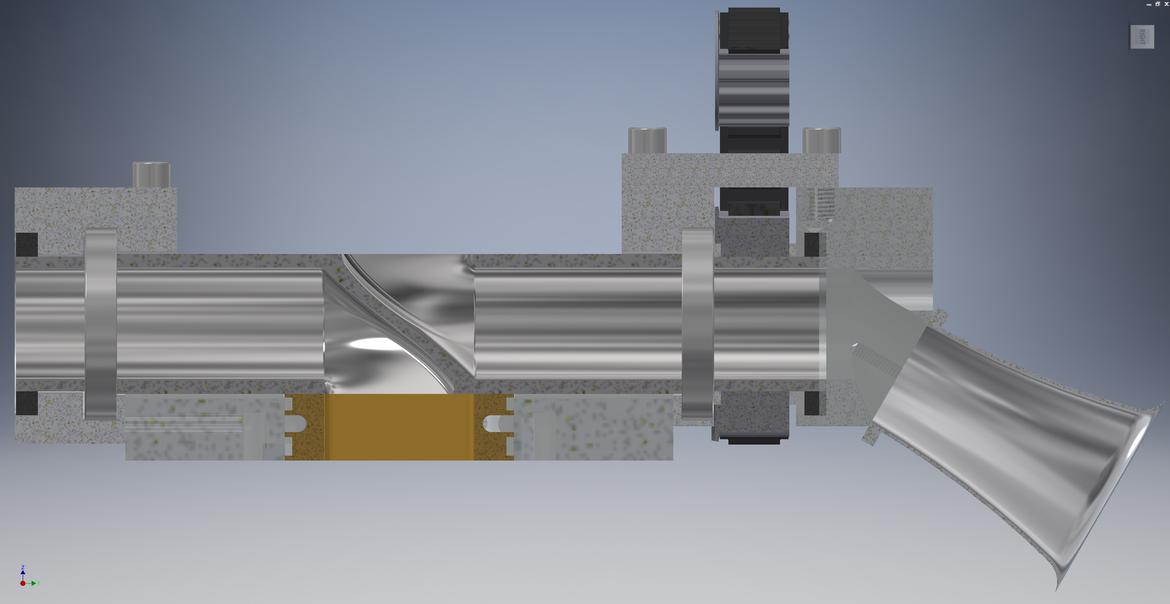
The passageway for the air is amazing.
That idle is fantastic. It reminds of something old and aviation related.
So I'm curious... have you put the head on a flow-bench?

Ian F
MegaDork
10/1/18 9:36 a.m.
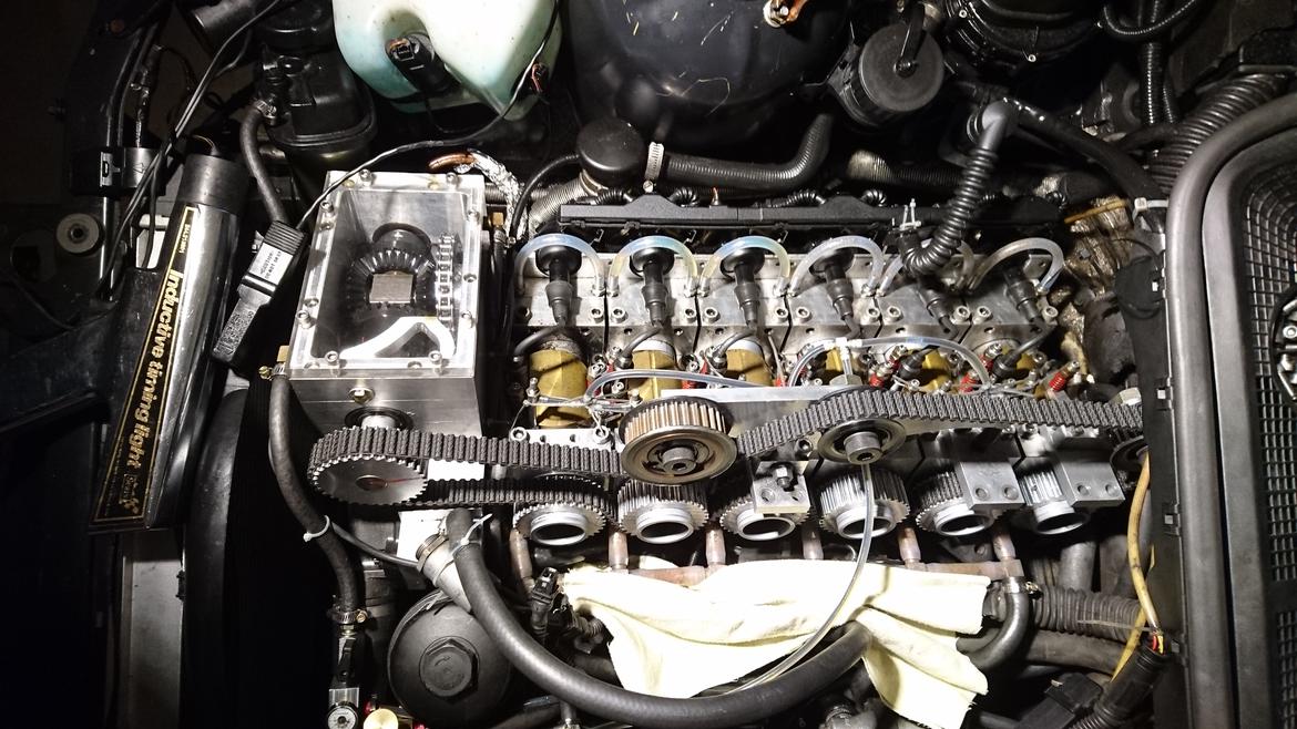
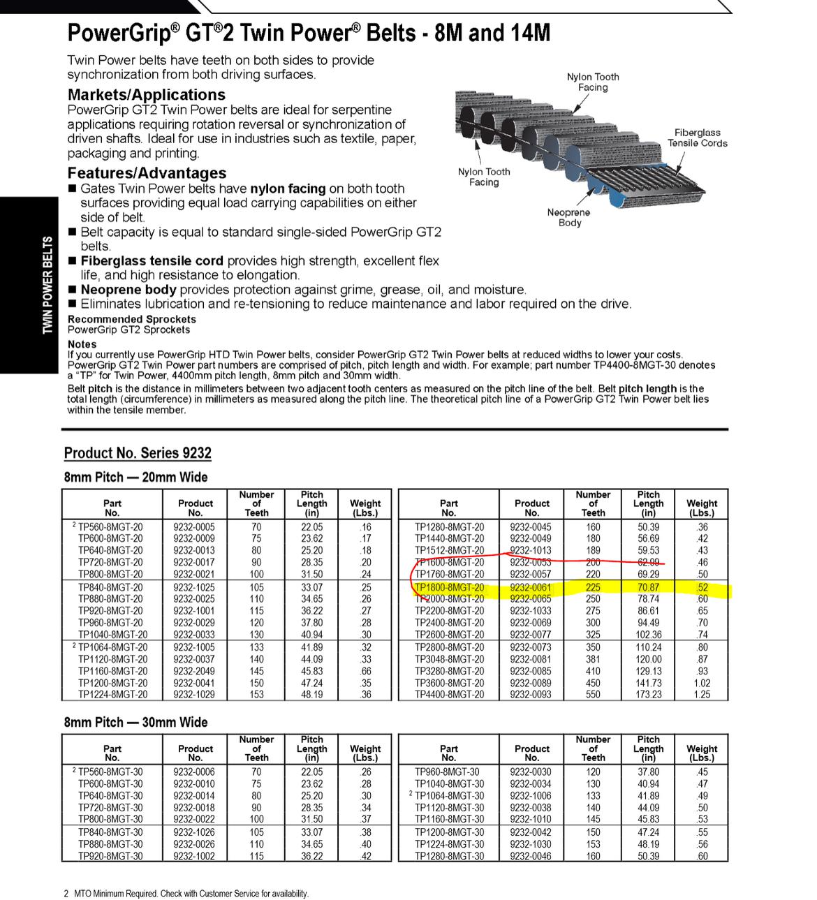
That looks like the mother of all toothed belts. 
How did you lock all of the valves in place when setting the belt tension?
In reply to ProDarwin :
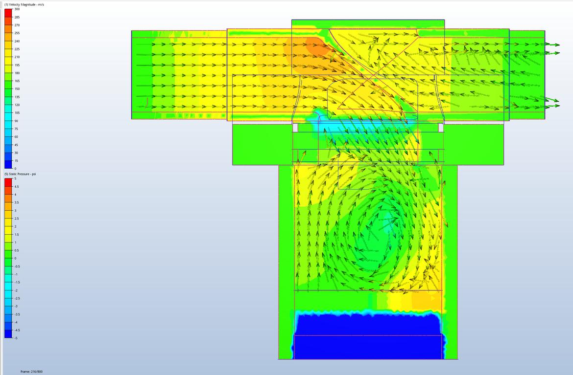
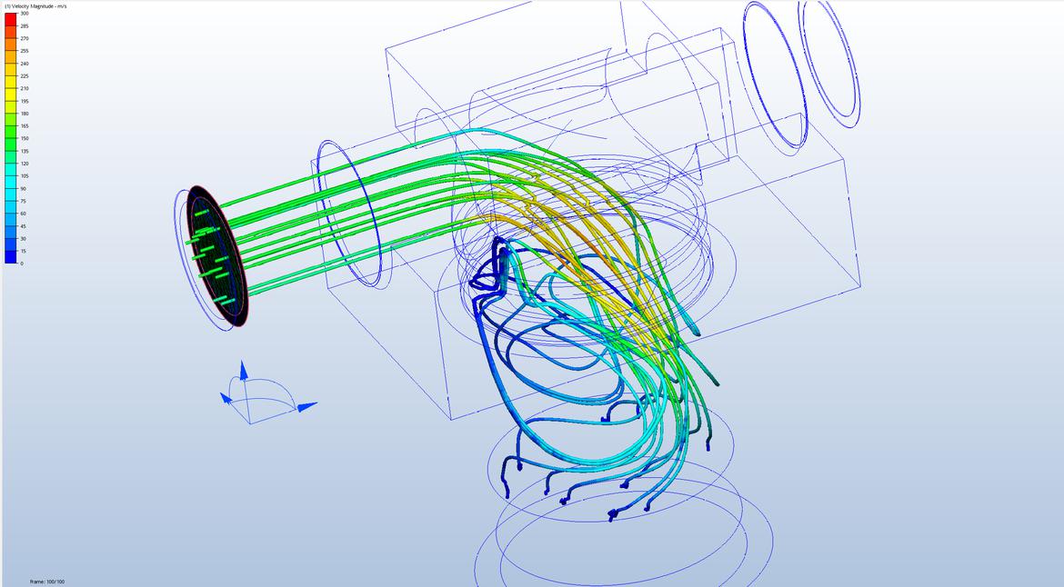
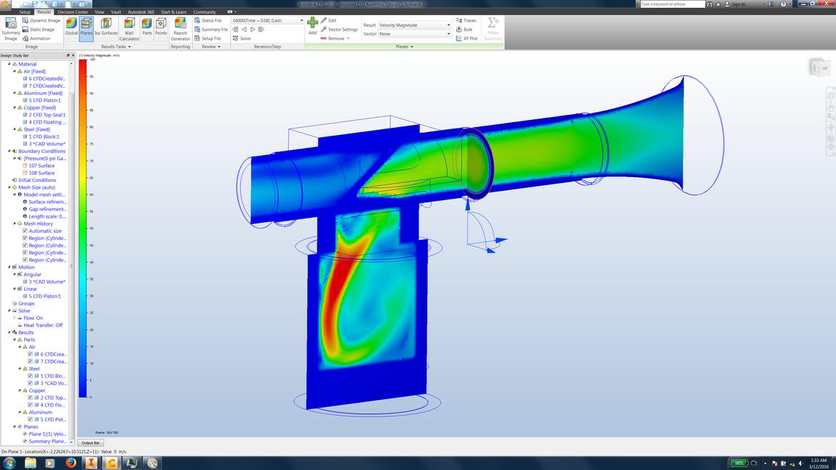
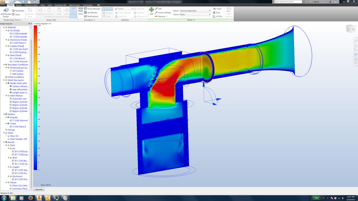
No, but if the head comes off again, I want to make my own flow bench (or find someone) and compare it to the stock head. Here's some CFD I was playing around with.
A video of the CFD. https://youtu.be/afi5tcE-qkA
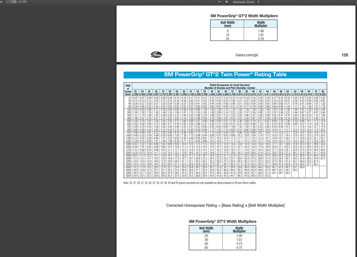
On the chart below, I figure I'm at about 250-260 degrees on the left most column.
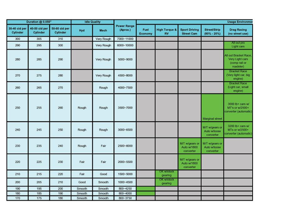
Ignore all other lines except for the black lines. That is my relative valve timing.
Ian F said:
That looks like the mother of all toothed belts.
How did you lock all of the valves in place when setting the belt tension?
Setting the timing was tricky, as you had to position each valve and feed the belt through the whole system. If you didn't take the intake off, it was 100x more difficult, but we did it a few times. Over 2 years, we improved this process by sending dowel pins through the sprockets into the valves for the chain set up so it was perfect every time. With the belt, it would stretch and also skip teeth under hard deceleration (or early on when you shifted from 1-2) or when you turned it off. Now you can change the timing in less than a minute instead of 5 hours... much better for morale of the person turning the wrenches. We also have improved the process of removing the entire intake system to the point you can do the whole thing in 60-90 minutes, in and out.
And yes, it was rated for about 30 hp. They were about $100 a piece and I broke 5 or 6 of them. Every time they saw oil, fuel or heat, it would break. Rubber doesn't like those things(having worked for a company that does this). I think we got 10 hours out of one.
Ian F
MegaDork
10/1/18 8:32 p.m.
Neat. I wonder if it would help to do it the way VW does it with some of the TDI engines. The cam sprocket (and injection pump sprocket) floats on the cam during a belt change. The cam is locked and the injection pump is locked, but only the crank sprocket is fixed. Install the new belt, set the tension, then lock down the cam and pump sprockets.


