1 2 3
adoyle88
adoyle88 New Reader
7/23/15 8:02 a.m.

It is hard to believe that it has been over 2 months since my last post. We've been quiet on here because my dad and I have been dividing every waking hour between the shop and the kit car. With the Goblin P2 frame now heading off to get powder coated, I figured it was a good time to catch everyone up before we start assembly.

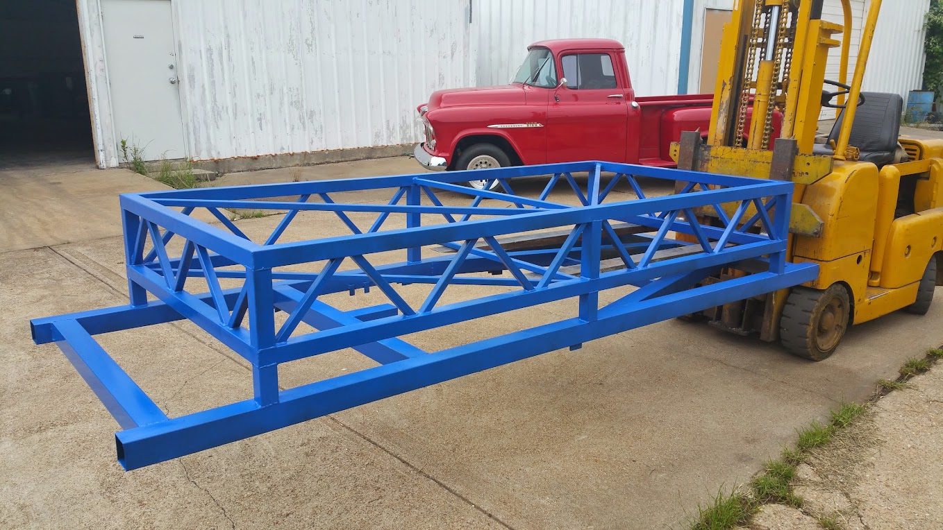
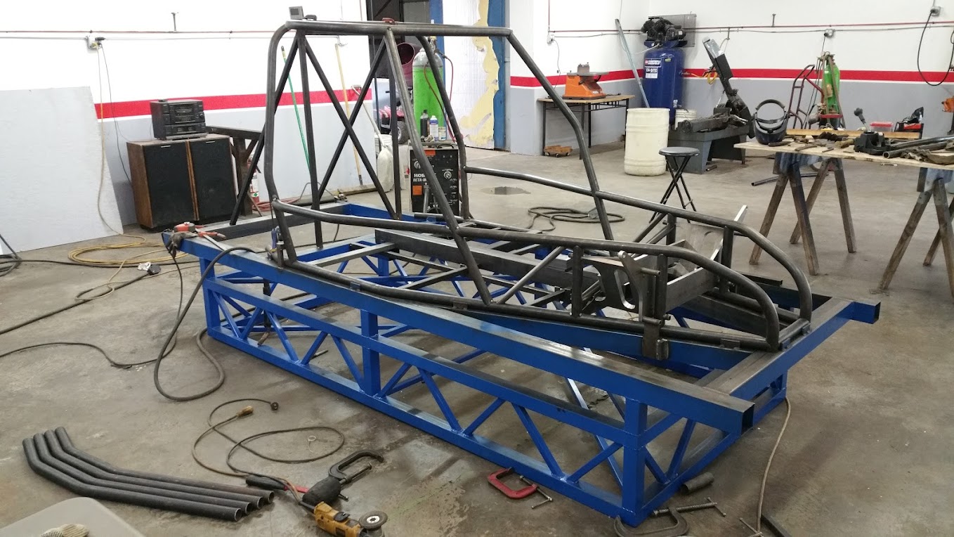
After finishing the CNC tubing bender long ago, we prepared to fabricate the second chassis by first building a very rigid frame to act as a chassis jig. We had it finished and painted on May 22.

DF Kit Car chassis jig freshly painted

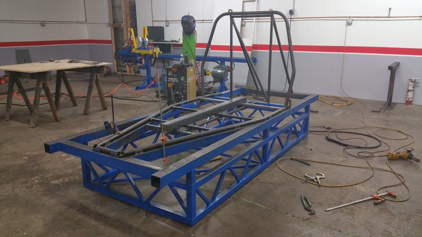
We started building from the floor up: lower frame rails, tunnel and floor bars. Then we added a temporary framework on the rear of the jig to install the main hoop. I was keeping track of the target bend measurements and the actual bend measurements of the tubes so that I could keep tweaking my bend gain and spring back equations. It worked out really well.

DF Goblin prototype 2 floor bars and main hoop on jig

To align the front suspension, we built an aluminum fixture that bolts directly to the chassis jig. This fixture holds the mounting tubes for the control arms and front shocks in the correct place during fabrication.

After locating the suspension mounts we made the upper frame rails, roll cage front down tubes and halo.

front suspension fixture and roll cage

On the ground in that last photo you can see the upper door bars. Two of them are welded to the car and the other two became tools. The upper door bars make the car slightly harder to climb into than the short diagonals on the first prototype but they offer a lot more intrusion protection for the driver and passenger. You can see them installed in the next photo.

We made some simple mounts for the new seats and installed the driver seat to test the fit.

DF Goblin prototype 2 upper door bars, dash bar and pedals

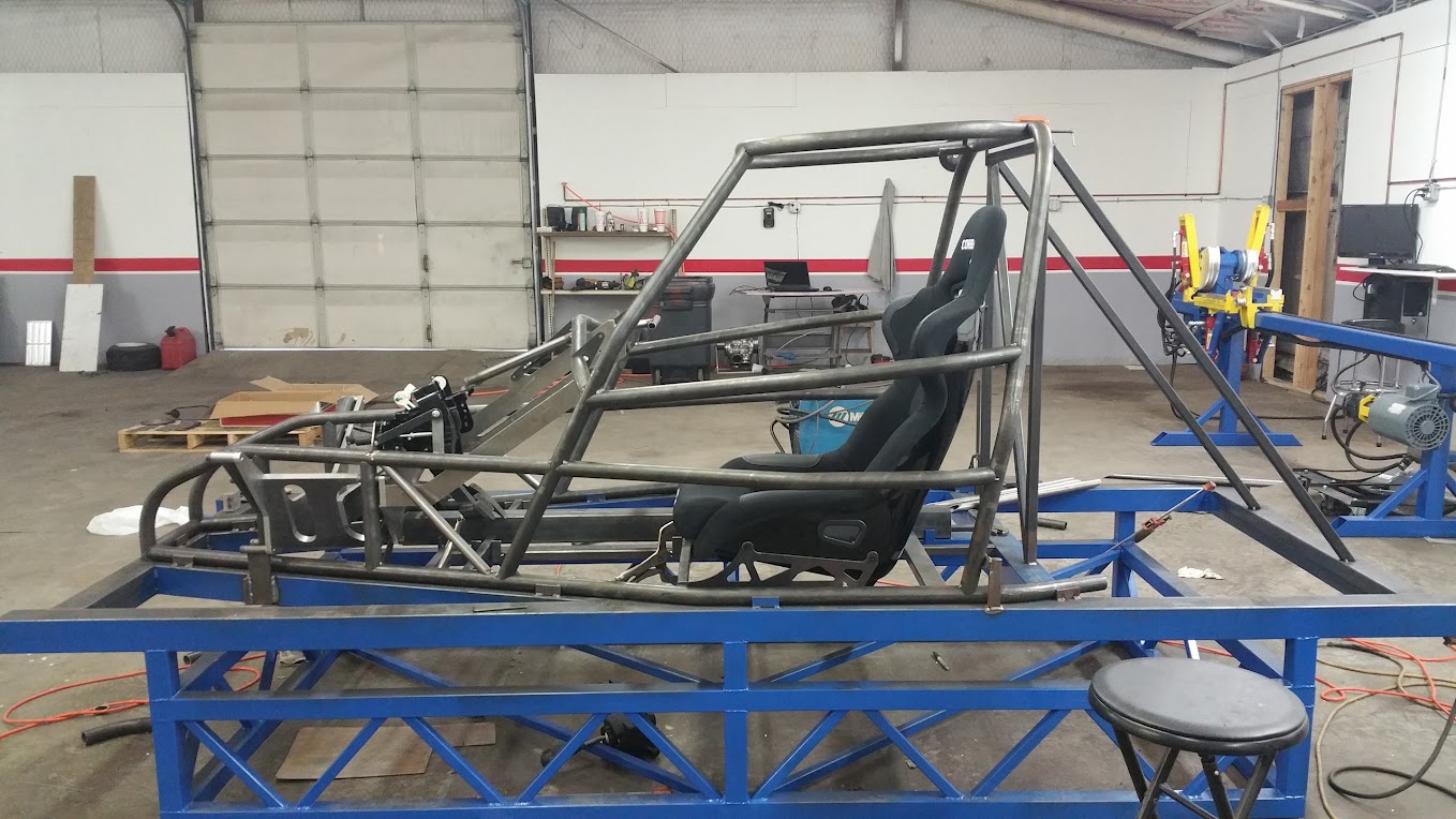
In that last photo you can also see another aluminum fixture extending back from the front suspension fixture. This one is used to locate the dash tube and dash accessories.

The first prototype didn’t have a hoop diagonal but this prototype, and all Goblins from now on, will have a diagonal and shoulder harness bar welded in.

Moving further toward the back of the car, we built a removable square tube frame to locate the upper strut mounts. This frame will also be used to locate the main hoop in future builds. The rear cage went together pretty easy.

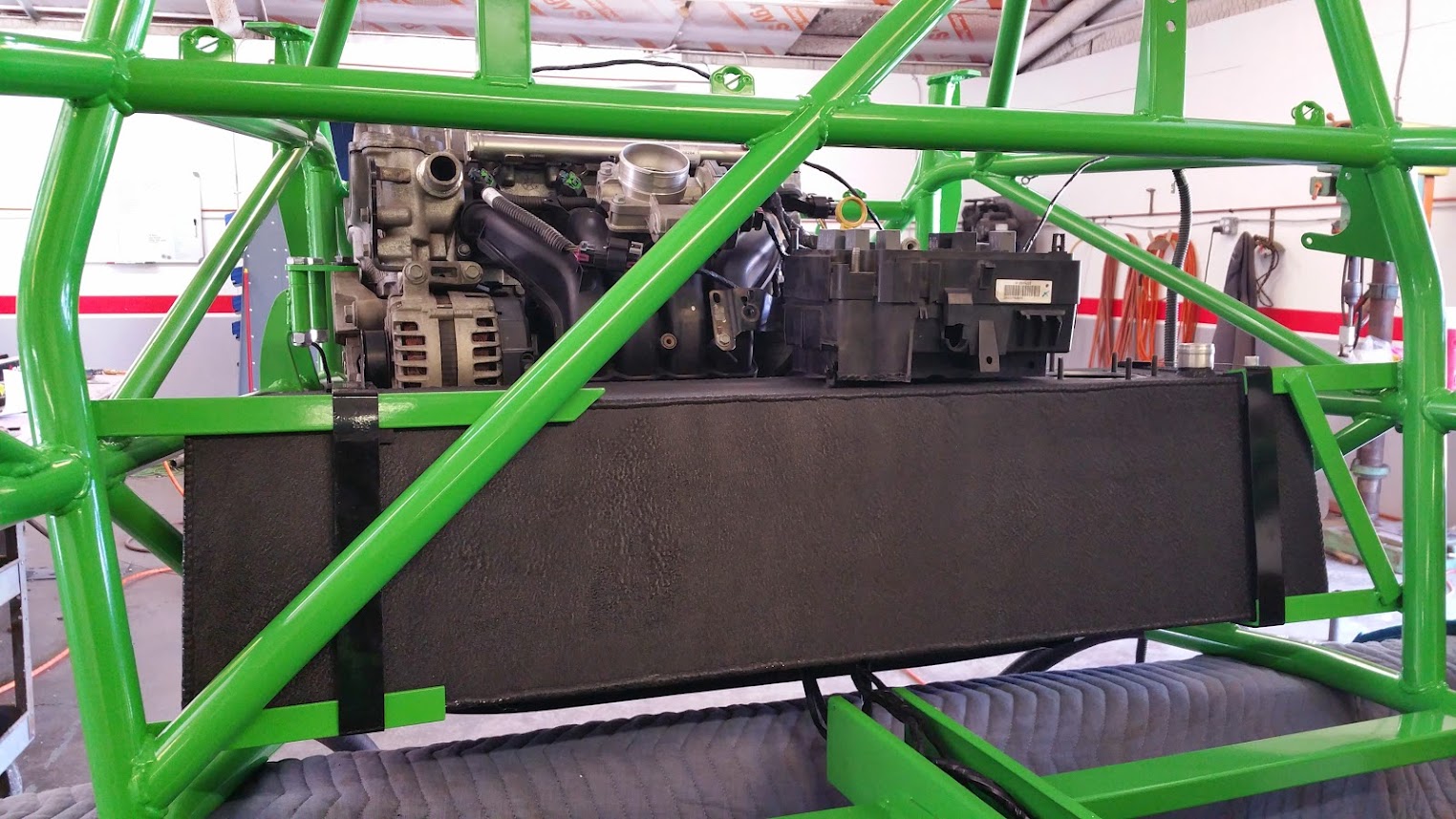
We lifted the chassis off the jig to install a donor subframe and engine. With the subframe attached we were able to make the upper engine mounts.

DF Goblin prototype 2 rear cage with engine installed

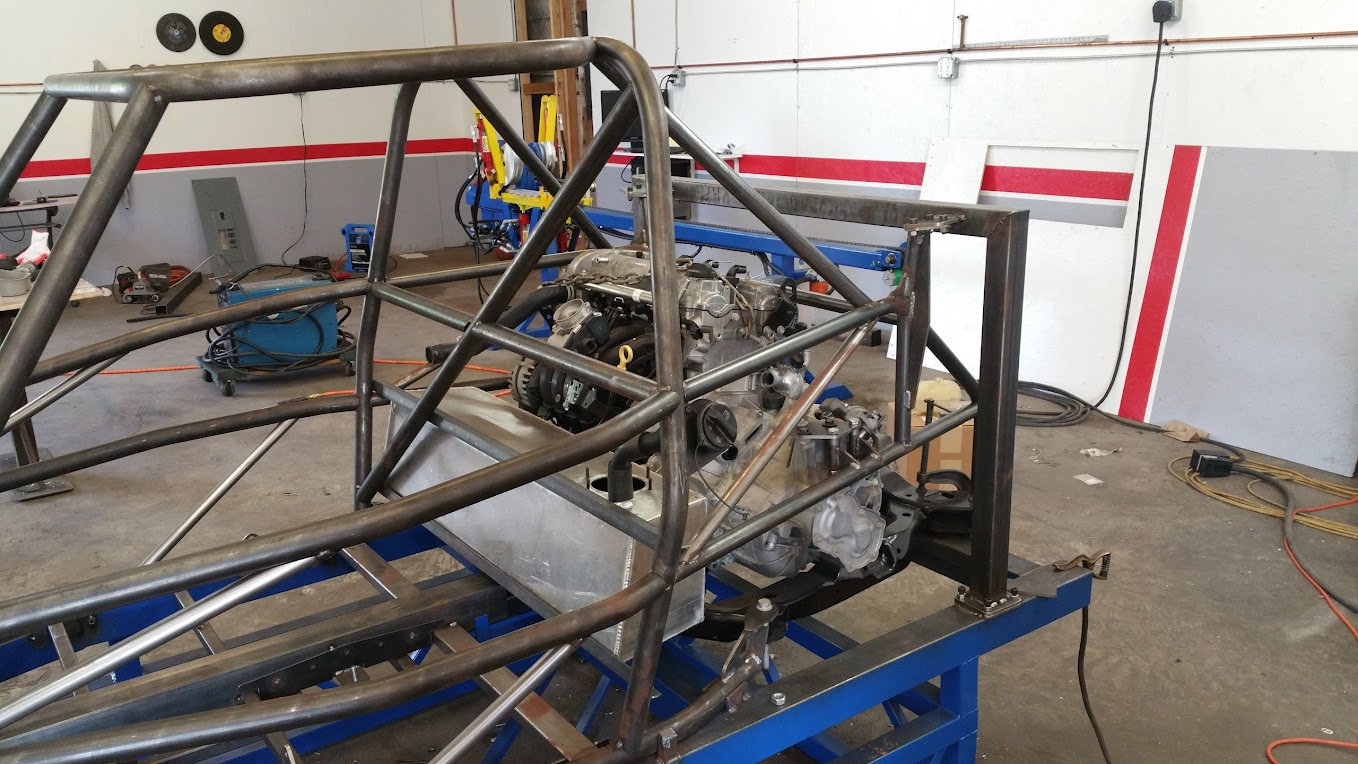
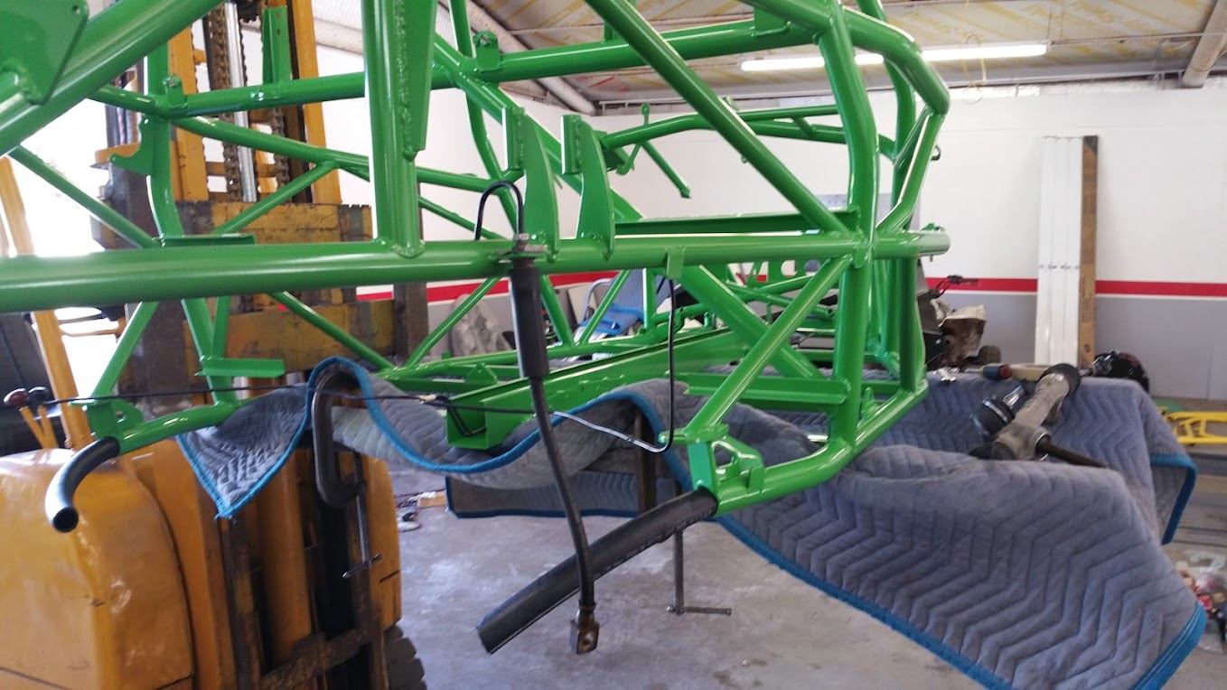
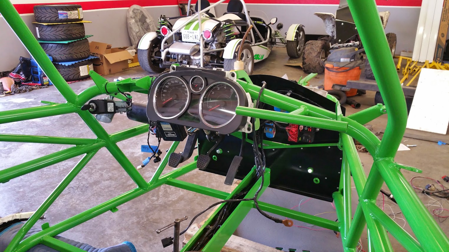
Observant viewers noticed a big change to our car in the last photo. For safety reasons, we moved the fuel cell to a more central location in the car. With the tank being behind the seats, it is better protected from being punctured in a crash and, as an added bonus, it is now larger than the first prototype (10 gallons vs. ~8 gallons).

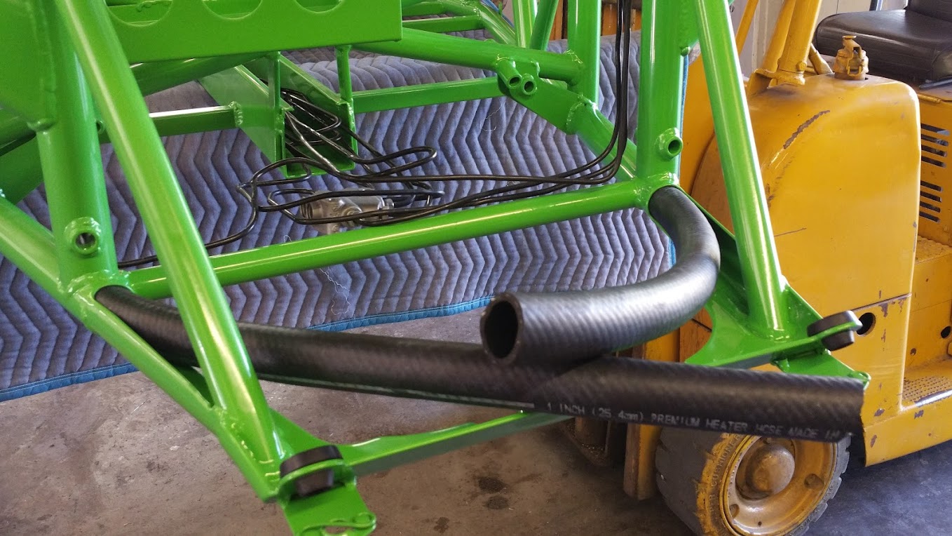
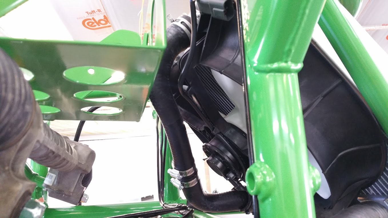
So with the fuel cell in the back, where’s the radiator? Well, its located exactly where a radiator should be: at the front. There wasn’t room for the donor’s single core radiator in the nose, so we changed things up to use an aftermarket aluminum 3 core radiator. This required a change to the front of the frame and the fiberglass nose will have to be modified as well. The new nose will be shorter (far less likely to scrape the ground) and will have a nice big opening for air.

Another bonus of moving the fuel cell to the back was that it opened up a lot of room up front. This allowed us to reposition the steering rack in a way that makes it possible for us to use the donor Cobalt’s electric power steering. On top of that, we had room to install the donor brake booster. Both of these will reduce fatigue while driving around town and on the track but either can be removed if the driver doesn’t want them.

DF Goblin prototype 2 radiator in the front, eps, brake booster

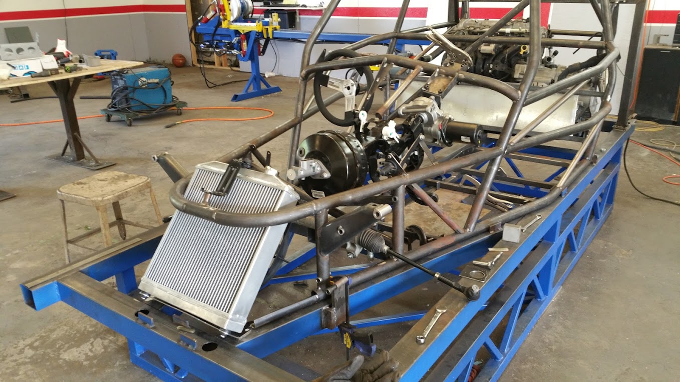
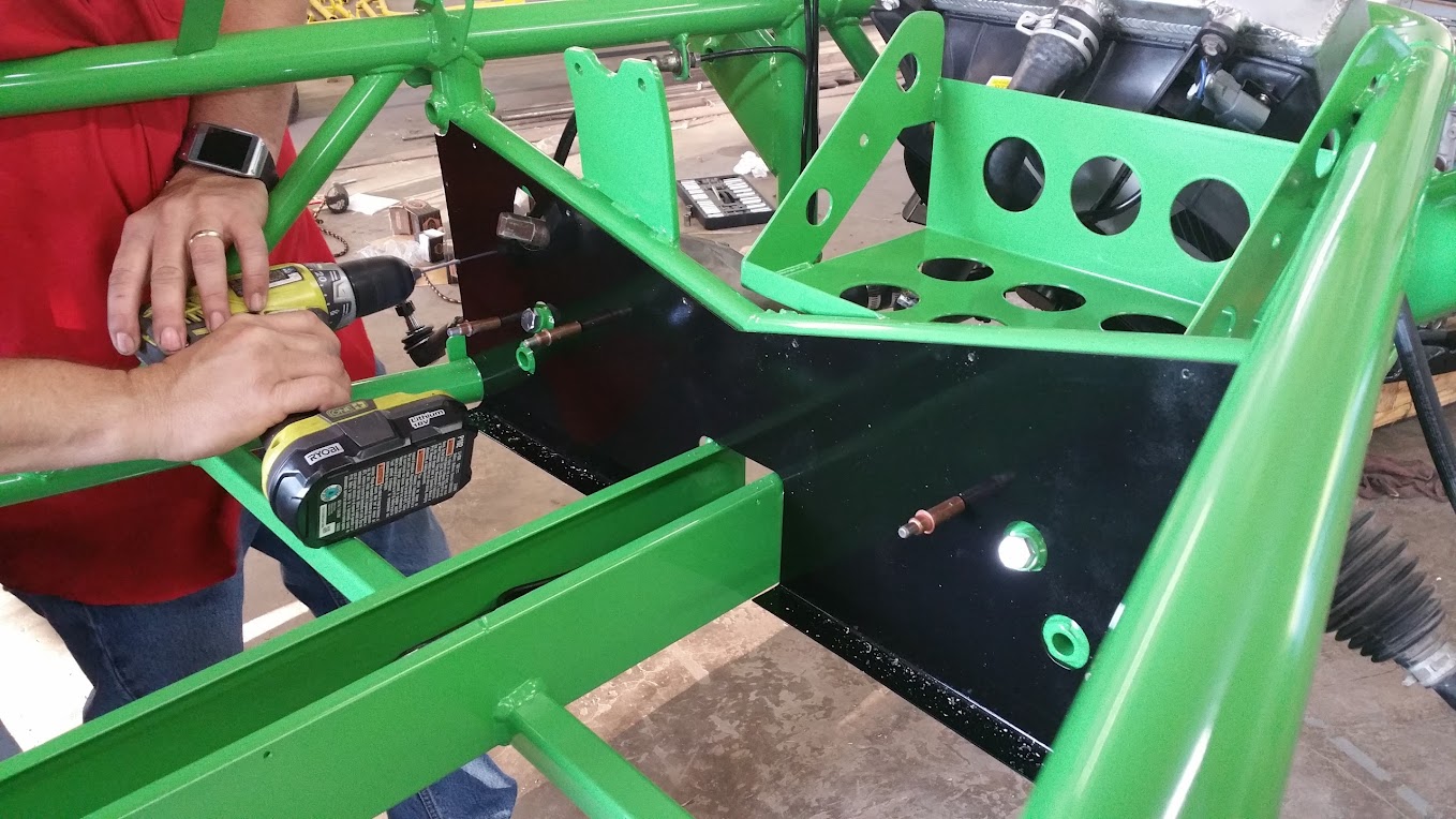
In that last photo you can also see our new front shock mount towers. We made them by cutting flat plate and forming them with a die on our hydraulic press. They are made as halves and then welded together.

I mentioned earlier that some of the tubes (specifically the extra door bars) were turned into tools. Here is a photo of our notching tools:

DF Kit Car notching tools

We set up a notching system that uses our largest drill press. To notch a tube for the car, you clamp the cut and bent tube into the appropriate tool, hook the plates on the end of the tool onto a fixture on the drill press and then notch the tube. It is easy, quick, consistent and didn’t cost us a bunch to set up.

With the frame complete, we moved on to the front suspension.

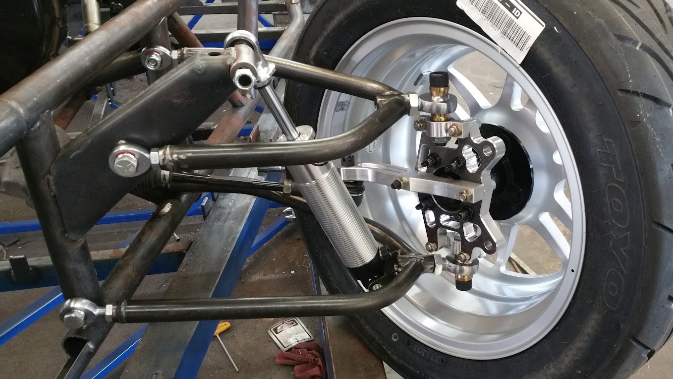
The control arms of prototype 1 were very simple but they were a little tight around the coilover so we weren’t able to stand the shock up much. On prototype 2, we wanted the shock and spring to be more effective, so we had to make more room for the shock to stand up. This was achieved by designing the control arms with bends in them to clear the coilover.

To bend the control arms we machined press dies and used the hydraulic press. Then each tube was snapped into a fixture on a CNC mill and the ends were cut. Finally, we fit the tubes into a weld fixture and welded each control arm.

After completing the control arms, we started on the steering knuckles. Just like the first prototype, we machined the uprights out of .75 inch aluminum plate. Instead of 1/2 inch rod ends out at the hub, we used chrome-moly rod ends with 3/4 shafts and 5/8 balls. The inner rod ends are still 1/2 inch, but they have been upgraded to chrome-moly as well.

DF Goblin prototype 2 front suspension

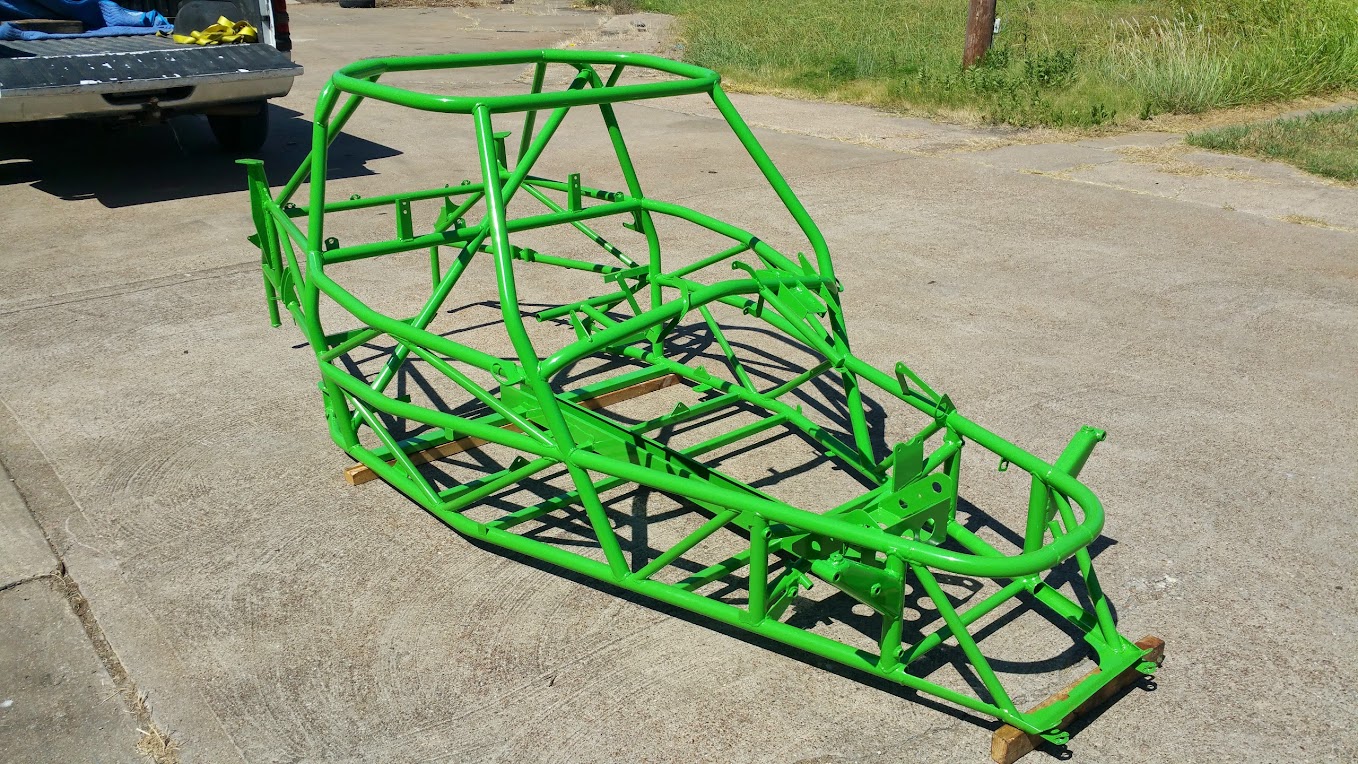
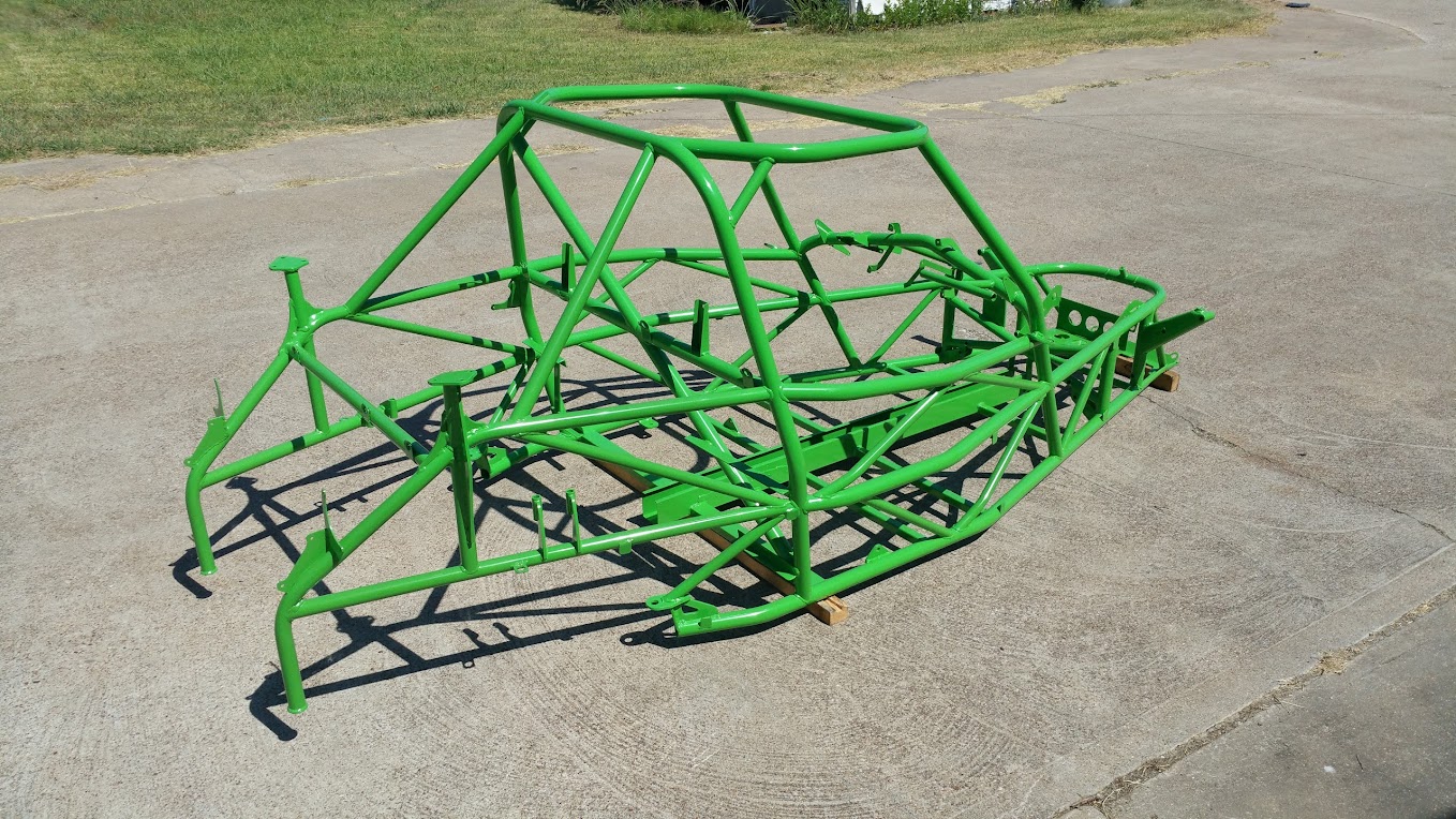
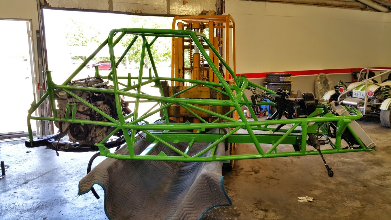
The rear of the car was easier to assemble and in no time we had the car down on its own four tires:

DF Goblin prototype 2 roller on its own four tires

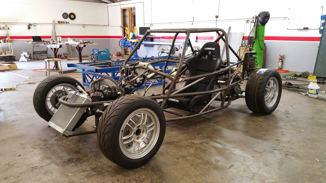
After taking that photo, we took it all back apart and welded out the chassis. Now it is at the powder coater getting a nice goblin green coating. Once it gets back, I’ll keep you all updated as we assemble it.

wvumtnbkr
wvumtnbkr GRM+ Memberand SuperDork
7/23/15 8:16 a.m.

hnnngggg.

Those door bars DO look rather high! Are the street versions of this car going to have those that high as well?

Mad_Ratel
Mad_Ratel HalfDork
7/23/15 9:18 a.m.

Not a huge fan of the strut AND upper control arm mounted to that lever. The lever is pretty beefy looking but the tube holding it does not appear to be as strong...

java230
java230 New Reader
7/23/15 12:15 p.m.

Looking way better than the first design! I like the changes.

Mad_Ratel wrote: Not a huge fan of the strut AND upper control arm mounted to that lever. The lever is pretty beefy looking but the tube holding it does not appear to be as strong...

Agreed. Seems like it should be braced to the top tube at least.

Mad_Ratel
Mad_Ratel HalfDork
7/23/15 1:38 p.m.

It also has no placement forward aft. Which means that any turning or braking forces are twisting the HECK out of it.

Keith Tanner
Keith Tanner GRM+ Memberand MegaDork
7/23/15 1:53 p.m.

You'll want retaining washers on each side of those rod ends, too.

Mad_Ratel
Mad_Ratel HalfDork
7/23/15 2:39 p.m.

Looking closer. I just do not like that lever at all. I love your design overall dude but your shock only bolting to one side imparts HUGE twisting forces on the lever and therefore your tube. It'll hold up for a while and then your welds/metal around the welds will fatigue fail. Could you not modify the lever so that the strut is bolted into the end? (through bolt towards the center of the car.)
I'd also make that lever either more triangular and run it down to the bottom and up to the top tube while also wider ... Just a WHOLE lot of force goes through there. There's a thread on locostusa about braking forces on control arms. (I think.)

edit: corrected strut to shock.

Keith Tanner
Keith Tanner GRM+ Memberand MegaDork
7/23/15 2:41 p.m.

It is a shock and not a strut - that implies different forces in cornering and braking at the top of the shock. You'll get those through the control arm instead. But on full bump, figure at least a 3g hit.

Mad_Ratel
Mad_Ratel HalfDork
7/23/15 2:45 p.m.

Keith, the shock and the upper control arm are both bolted to that lever.

Keith Tanner
Keith Tanner GRM+ Memberand MegaDork
7/23/15 2:53 p.m.

The shock and one side of the upper control arm. And the control arm mounting point is not in single shear and is closer to the mounting tube.

tuna55
tuna55 UltimaDork
7/23/15 2:56 p.m.
Mad_Ratel wrote: Keith, the shock and the upper control arm are both bolted to that lever.

!!!

Yes, I see this and now am scared of it too

Mad_Ratel
Mad_Ratel HalfDork
7/23/15 3:30 p.m.
Keith Tanner wrote: The shock and one side of the upper control arm. And the control arm mounting point is not in single shear and is closer to the mounting tube.

You are more of an expert than I. He'll have tons of weld bead on that lever.

adoyle88
adoyle88 New Reader
7/25/15 3:05 p.m.

We had drawn the front shock mounts with .25 inch thick gussets, .125 inch thick shock towers and 1.5 inch x .095 DOM tubing for the rest of the front frame but after researching locost front frame designs and discovering that quite often they are constructed of .065 wall 1 inch square tubing, our design suddenly looked overkill. So we modeled a locost front end similar to some we saw online (we ended up with a design much like McSorley's build) and compared it to ours on SolidWorks.

Removing the gusset and comparing the current design in SolidWorks vs the .065 wall square tubing front of the locost, we found similar deflection distances and factors of safety when a 1500 lb force was applied. In real life though, our front end is lighter and shouldn't see the same loads as a front engine locost.

This isn't to say we won't go back to the gusseted design, but for prototype 2, we wanted to test without it. We are going to be making a few tools to help us monitor the front end during testing. P2 is going to get abused for this very purpose. We also have an idea about building up a front end and testing it on our hydraulic press.

Thanks for your concerns. Glad to know someone cares about us not wounding ourselves or others.


Moving forward on the prototype build, we got the chassis back from the powder coating shop. In the past, we've always painted our tube frames with rattle cans, so this was a first for us. We are very pleased. It seems that powder coat makes every weld look about 10 times better.

As for the color, you can probably tell that we got some inspiration from JThw8's Lot Lizard.

DF Goblin Prototype 2 powder coated chassis front view

DF Goblin Prototype 2 powder coated chassis rear view

We like how it looks and can't wait to see it built up. Also, the light green color will make it easier to monitor the joints for cracks or bends.

I'll post more photos as we cross things off the build list.

adoyle88
adoyle88 New Reader
7/26/15 11:35 a.m.

We kicked off assembly by installing the coolant hoses that connect the radiator in the front with the engine in the back. We read about rock crawlers running the coolant through the steel tubes of their frames but we wanted an extra layer between the frame and the coolant so we decided to pull 1.25 inch heater hose through the tubes.

The hose is a snug fit in the 1.5 inch .095 wall tubes so we aren't concerned about chafing. To pull them through the tubes, we cut one end of the hose at an angle, poked some holes and tied a long piece of rope to it. After using an air blower to send the rope through the tube, we spritzed some tire wet on the outside of the hose and pulled it through. It was way easier than we had expected. We repeated the process for the second tube without any trouble.

Here is a shot showing how we attached the rope to the hose:

rope tied to coolant hose

Hoses up near the radiator location:

coolant hoses by the radiator

And at the back of the car (not sure why the color is all weird in this shot):

coolant hoses at the rear of the car

In those last two photos you can see that the next thing we did was install the brake lines. We are using the donor Cobalt's brake lines. Since they are so long, we had to wind them back and forth to eat up some of the length. Luckily, this portion can be hidden away in the tunnel. We've decided that we are going to ship pre-made brake lines with the kits because it is too hard to work with the ones that come with the donor.

Next we installed the steering rack and the radiator. By splitting and splicing preformed radiator hoses from the auto parts store, we were able to plumb the radiator.

DF Goblin prototype 2 radiator plumbing

We riveted in a two piece front bulkhead. This will seal to the floor sheet metal on the bottom, to the hood on the top and the side panels will seal the outside edges to keep the driver compartment from being super heated by the radiator.

Lower bulkhead being installed: DF Goblin Prototype 2 lower front bulkhead

After installing the upper bulkhead, we mounted the pedal boxes (one for throttle and brake, another for the clutch).

DF Goblin Prototype 2 pedals

Now we are working on the clutch hydraulic line. I'll try to post another update tonight.

Mad_Ratel
Mad_Ratel HalfDork
7/26/15 2:26 p.m.

You guys do some top notch work.

NOHOME
NOHOME UberDork
7/26/15 5:28 p.m.

I am way impressed with this whole thing. I would also love to see the business plan for wherever you are going with this.

adoyle88
adoyle88 New Reader
7/27/15 8:08 a.m.

Thanks Mad_Ratel and NOHOME.

In reply to NOHOME: Our basic business plan at the moment is to try not to get too distracted with the kit car so that we can keep the CNC machine shop going too. This has resulted in my dad and I working 60-80 hour weeks with the overtime (and the occasional shop time) going to the kit car. Luckily, two of my brothers and our shop manager Jeff keep the shop going even when we are distracted.

Now that we are through the tooling process, it won't take long to start sending out stage 1 kits (frame, fuel cell and enough to get the engine in and running). There are at least four people that have let us know that they have purchased donors and are ready to start transforming them. We don't want to keep them waiting too long, but we are going to test Prototype 2 first, as mentioned in the previous post.


We started on the car yesterday at 6:30 AM and planned to work late last night but we only made it to about 7:00 PM. After my last post we installed the clutch hydraulic line.

The original line was about two feet of Nylon-12 tubing. This is a type of nylon commonly used for fuel, brake and other hydraulic lines because it doesn't absorb moisture like other nylons. We bought a roll of the tubing and spliced several feet of it into the original clutch line using 300 PSI acetal push connectors. We routed the line through the tunnel with the rear brake lines.

Next we temporarily mounted the BCM to the front upper bulkhead. There are several wires in the main harness that have to be extended so we need the BCM in place to see just how long they need to be.

The electronic power steering bolted in next. It is mounted with a single angle bracket at the moment. We are going to monitor the rigidity of this setup and if we aren't happy with it, we are going to add a clamp-on adjustable bracket to support the motor near the frame rail. It needs to be adjustable so that if you need to adjust the height of the wheel, you can also adjust the height of the EPS. It will have about 1.5 inches of adjustment.

DF Goblin Prototype 2 electronic power steering

Next, it was time to mate the engine-transmission-subframe assembly to the chassis. The subframe has four large bolts that connect it to the frame. The engine is supported by two mounts on the subframe (currently they are the stock rubber mounts but we will be making solid replacements) and by two mounts on the chassis. The process is pretty easy. You just lower the frame down over the engine and bolt things up.

DF Goblin Prototype 2 engine mated to subframe

DF Goblin Prototype 2 engine mated to subframe wide view

We ended the day working on the body and dash wiring harnesses. The wires for the stereo, doors, HVAC controls and other unused systems were cut out (we will use these wires to extend the harness). Most of the wires can reach from the fuse block near the engine to the BCM above the passenger's feet but one plug has 16 wires that need to be extended. So with the harness now thinned out, we've got to lay it in the car and measure how much the 16 wires need to be extended. Then it is just a matter of snipping, soldering and heat shrinking the wires.

After running all the wires, we are going to move on to the fuel system and get the engine cranked up.

RossD
RossD PowerDork
7/27/15 8:15 a.m.

Awesome work! Keep the updates and pictures coming!

T.J.
T.J. UltimaDork
7/27/15 8:17 a.m.

I love threads like this, but they tend to make me feel unskilled and lazy. Keep the updates coming.

Mad_Ratel
Mad_Ratel HalfDork
7/27/15 9:47 a.m.

random question, how many miles on goblin 1 now? still enjoying it?

how much room for a larger person?

adoyle88
adoyle88 New Reader
7/27/15 10:13 a.m.

In reply to Mad_Ratel:

We've put somewhere around 1200 miles on Goblin 1, but my brother and his wife have started driving it all the time so that number is rapidly increasing.

I enjoy driving it because it feels like driving a grown up go kart on the road. I've never ridden a street bike, but I assume driving our car is very similar, and I can definitely see the appeal of being out in the open air. Out on the highway a helmet is recommended because car tires are far noisier than expected but around town it isn't bad without.

I'm nearly 6 feet tall and 250 pounds and I fit with the stock Cobalt seats in Goblin 1. In Goblin 2, the Corbeau seats give a lot more room and we were also able to move the pedals 1.5 inch further toward the front. With the seat in its full back position, the throttle pedal is uncomfortably far away for me so we think someone quite a bit taller can fit, especially if they are pretty lanky. (On a side note, we raised the main hoop on Goblin 2, so with the Corbeau seats there is a lot of head room)

Room side to side is great. We've had super seven type people tell us they were surprised by how roomy it is but apparently those cars are extremely narrow.

adoyle88
adoyle88 New Reader
7/27/15 6:03 p.m.

We got the bulk of the wiring and dash accessories installed. We still need to run the large positive cable from the battery at the front of the car to the fuse block in the back and a few other little things.

DF Goblin Prototype 2 gauges

DF Goblin Prototype 2 dash wiring

We also installed the fuel cell.

DF Goblin Prototype 2 fuel cell

Tonight we are going to try to finish all of the wires. Then we are going to tackle the fuel system. Let me know if there is anything you want to see a closer shot of. Trying not to over do it with too many photos.

mainlandboy
mainlandboy Reader
7/27/15 6:25 p.m.
adoyle88 wrote: Trying not to over do it with too many photos.

Don't worry, I don't think that will ever be a concern for anyone here!

DeadSkunk
DeadSkunk UltraDork
7/27/15 7:47 p.m.

Nice work. One concern on my part though. I look at those heater hoses and wonder if they are large enough to flow adequate coolant.

adoyle88
adoyle88 New Reader
7/27/15 8:20 p.m.

In reply to DeadSkunk:

The heater hoses measure 1.02 inside and the engine's water necks measure 1.04 inside. We were very happy to find heater hoses that had that close of an internal diameter and an external diameter very close to the inside of the frame rails.

1 2 3

You'll need to log in to post.

Our Preferred Partners
ZhilbzHAtg5NK7LGKTK40nHxiwioTZna0C799VCLMkcezqtvMLaO344d6zmifgAp