the first issue i needed to address was the exhaust. figure this requires the most room to do and the trucks headers were not going to work as they did in the truck. i had always assumed i would need to alter the headers to make them fit and i also assumed i would aim them forward to take advantage of the extra space ahead of the motor. we have also been toying with the idea of adding a turbo and this would give us room to do that. as luck would have it, taking the drivers side header and locating it backwards on the passenger side yielded some good results


ignoring the proximity to the miatas gas lines there is lots of room there. it is in the plans to bring the gas line in from the trans tunnel location anyway so that won't be a long term issue.
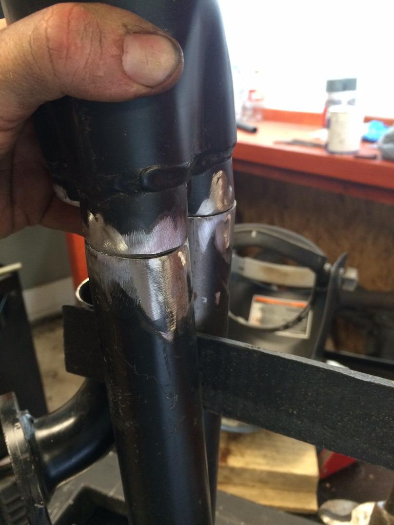
the other side? well, not so lucky. this side was full of issues. the header stuck out so far from the block on the two rear cylinders that is was hitting the firewall and frame rail... even after they had been cut back. it was also too long and had a dogleg turn at the end that would have brought it into contact with the subframe and water pump inlet. so...... time to cut it down. moving bits around a little and few tacks to field adjust. ..... i pulled the middle cylinder tube about 3/4" of an inch in to clear the frame.

i then took a full inch out of the rearward cylinder's tube so it could clear the firewall and frame location. i also turned the pipe down more to get it clear of the frame faster. it will be heat wrapped and will have a heat shield behind it on the firewall, but it is still really close to the pedal box and every bit of distance will help.


i needed to re profile the tube a little since the bend was not ion the flange point. i was a little hesitant about this but someone posted a story in the grassroots motorsports section about the negligible horsepower reduction that comes from "clearancing" a header with a hammer, so i figure this can't be too bad....
with the tubes in place i then had to reinstall the collector. getting all the way around the tube with the welder seems like a difficult proposition. I'm not sure how others do it so my approach was to cut one tube short of the collector. fully weld those two tubes all around while i have access.
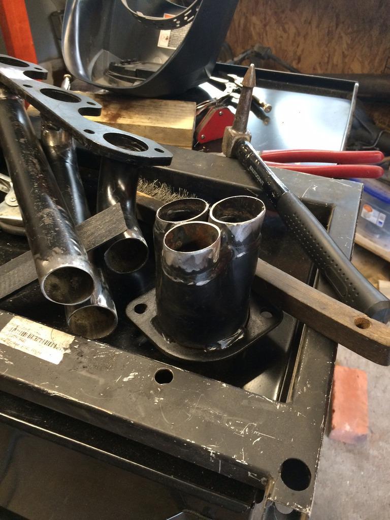

when that is done, i will fit a section of tube for the remaining part so it fits flush. then i plan to slice it open longitudinally. i figure then i can weld the hidden parts of this tube that are behind the other twi tubes from the inside of the sliced section. once in place, seam weld the sides and ends where it connects to the tube and collector to close it up. seems ike a lot of welding, but i can't figure out another way. if anyone has a suggestion I'm all ears as i haven't finished that part yet....
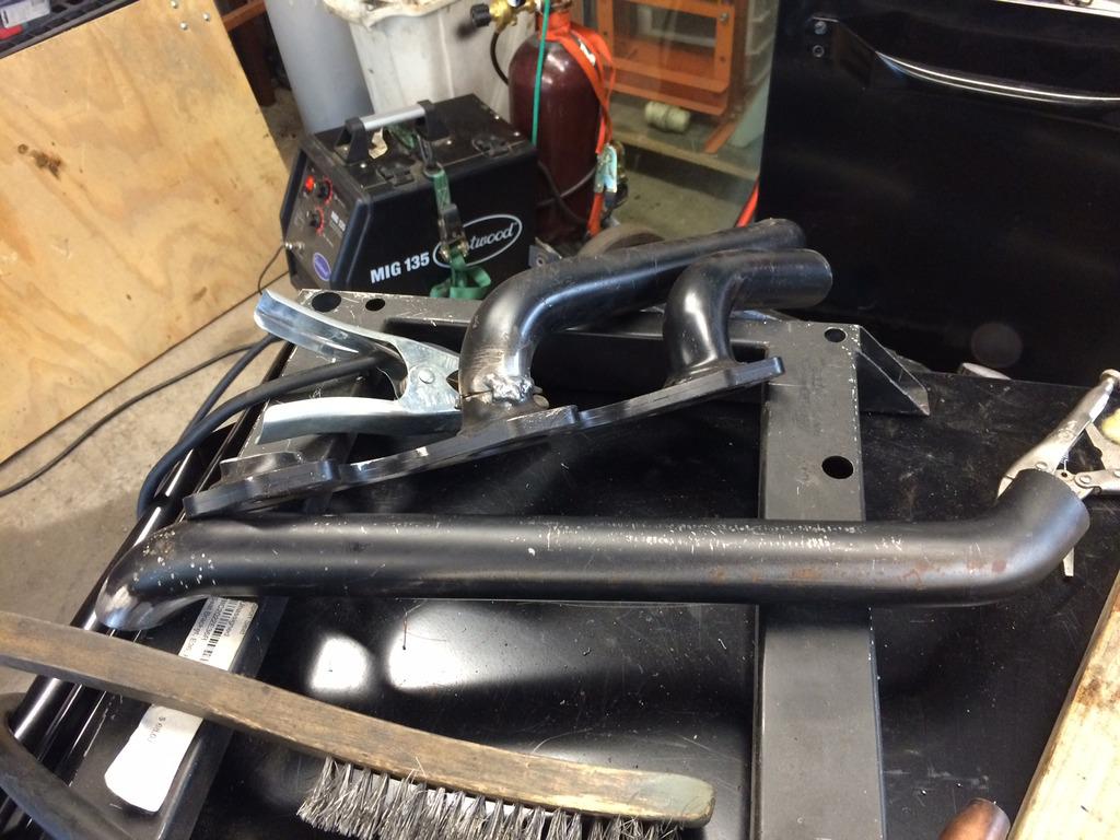
i did go ahead and test fit the completed piece though....

again, ignore the gas lines hanging across them as they will be redirected to the trans tunnel in the final fitting. but not too bad for a first time header build and an afternoon.
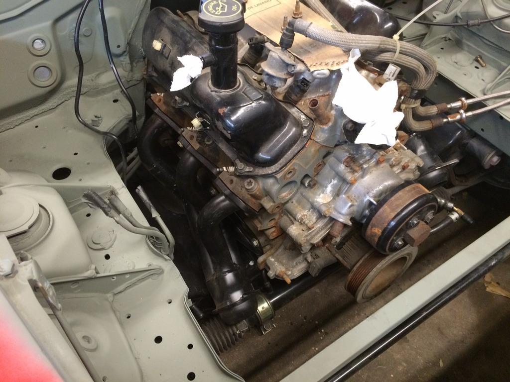
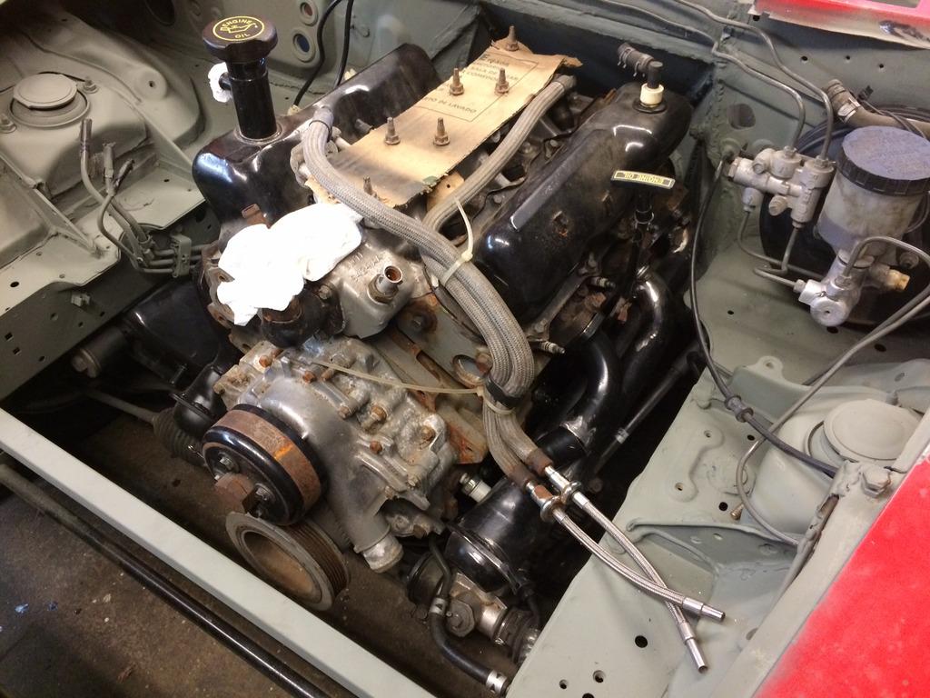
with the fiat body panels in place and the motor in its new home i did the final mock up piece for the weekend. in truth I've been putting it off for fear i would have to accept what i was pretty sure to be inevitable.

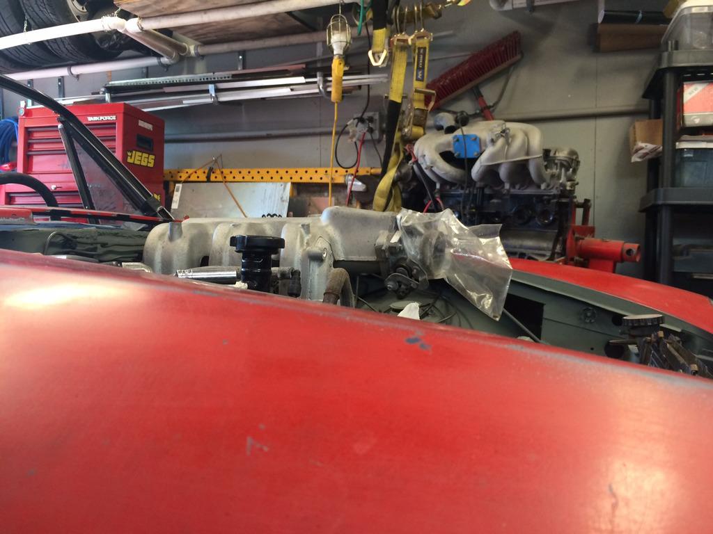
there is no way this intake will be fitting under the hood. i have grown fond of this little car and i would really like to keep changes to the hood line minimal and tasteful. oddly enough the bulge in the fiat hood is in exactly the right place for the oil filler cap to be as is, but the intake is a different story. the way i see it i have two options now. one, i can find another ford product that has the cologne V6 but has a shorter intake manifold that will work with tis motor..... and find it CHEAP. or , fab one that is shorter.... and also CHEAP! any ideas?

JoeTR6
Reader
6/13/16 1:45 p.m.
I was at first thinking early 70s Capri, but you probably want an injection manifold.
Yep. Definitely thinking fuel injection.
Find another intake, itb?
Or, what about a hood buldge, like the early 60s Ford thunderbolt scoop, only tasteful?
a quick wikipedia search say the 4.0 was only used in trucks...... im not optomistic i will find a shorter intake. i think i will be making one.
so the intake is dry the way it comes. i think my options are pretty wide open for materials. steel, aluminum, or composite seem plausible. id love to do alumnum but cant tig weld... so that leaves stel and composite. is there any reason to use one or the other from a boost poerspective? and would fiberglass be an acceptable composite material?
Fiberglass would be good, except the bolts would probably crack it unless you make steel flanges around the bolt pattern and somehow bond the fiberglass to the steel.
Here's an old thread on steel intakes. Nothing wrong with using steel, it's just heavier. Fuel and likely a bit of oil will keep it from corroding on the inside. Most older cars have cast iron intakes.
https://grassrootsmotorsports.com/forum/grm/mild-steel-intake-manifold/8425/page1/

NOHOME
PowerDork
4/8/17 6:09 a.m.
Don't you hate it when a great build that has gone dormant shows up and it turns out to be just a bump from another fan! So, even if no progress, what-up!
Hello?? is anybody out there???
Hey! Wheres the rest! Its like watching a good series and having them cancel it mid season.
I like these builds, it makes me feel like Im not the only nut in the tail mix.
Sorry peoples!
I needed a short break for keeping the homestead ( got a zoning variance to expand my shop space) , painted my DD, and had to rebuild the rear suspension on the track e30. But rest assured I am back in the shop working on the fiata again. I need to post out my pictures to keep the thread going. Included is the installation of the aluminum seat. Relocation of the steering wheel bracket, and the making of a composite intake.
I'm glad this got bumped as I hadn't seen it. Now keep the posts coming!

ok.....
so the consensus seems to be that people want to see the composite manifold work. i cant blame you. it has been the biggest elephant in my build's room for a while now. it started with some research. the most promising options were steel and composite and i really didnt want to add the weight of steel. the odd shaped ports would have also been a giant PITA so composite was the frontrunner. but there wasnt a lot of information about how.
fiberglass seemed to be more likely than carbon fiber and more research suggested that i could use styrofoam as a form and then dissolve it out with acetone. this would allow me to fully form the odd runner shape without risking any deformation with a split mold. i could also tailor the form and double check fitments with the hood and other elements before any serious material investment. i called several resin manufacturers and finally settled on an epoxy based resin with good heat resistance and the manufacturer indicated the acetone wouldnt affect it. (yet to be proven)
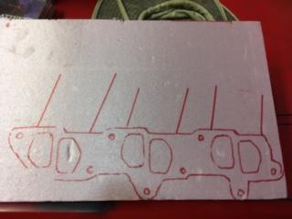
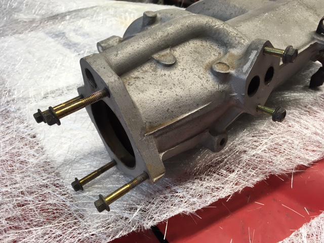
the trick to making a dissolvable form is to remember what you are making. you are not making the outer shell, you are modeling the airflow. it starts with an examination of the existing manifold and its connections to the engine, sensors, and the throttle body. you can see the manifold i was dealing with in previous images. i decided to use the existing manifold's aluminum base plate so i cut that off first. i then outlined that on some styrofoam

then i needed to add layers for thickness. i glued three layers of 1" foam together with powergrab. it didnt disolve the foam and when it is spread like butter and clamped overnight it forms a workable block of foam.
the next day i went at the block with cutting tools. i started with a utility knife to make crisp cuts in the top layer. i followed with an electric carving knife. this works best with the single blade type. the alternating blade type melts down the foam and doesn't cut well. single blade requires a stable base to hold the work but it is managable.
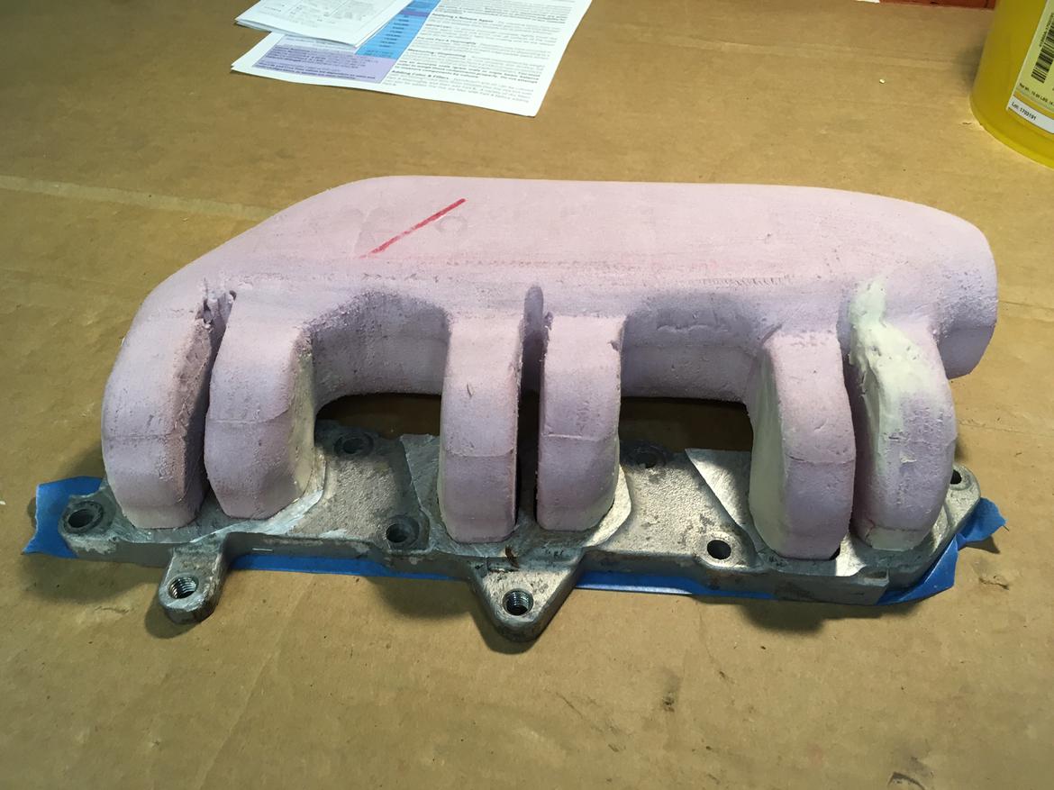
i followed this with a sanding disk on my grinder. messy but ridiculously effective. for finer work a set of files was employed to make the space between the runners and finer shaving. in the end the basic shape is finalized.....

there are three points of connection i needed to address on the intake. how it connects to the motor, how it connects to the throttle body, and how the idle air controller is integrated. the connection to the motor is accommodated by using the aluminum base plate. the throttle body i will address with the final casting work. the idle air valve needs to be addressed now. the picture below shows how the valve was connected in the factory intake...

i decided i would embed a channel in the mold. to make it work i located how i wanted the throttle body to clock on the end of the intake and where i could put the valve without it hitting the hood. i pressed a groove into the form with the cap of a sharpie. not high tech, but effective. more on this idle air tube later.... on to the first coat to form the backside of the idle air tube and affix the form to the base.


