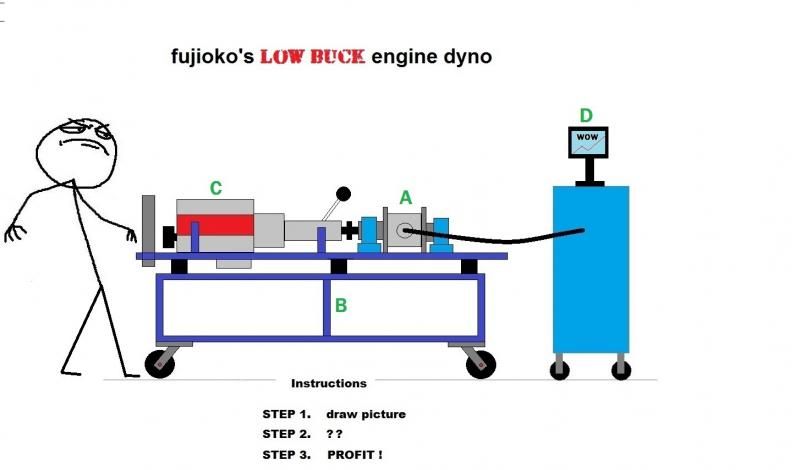
Like the title says, this is a low buck engine dyno project. I'm setting a budget of $1000.00 , lets see if that will be enough.
I guess I should clarify how I intend to use the dyno and what results I am expecting. This dyno is an extension of my Miata B3 project and will be used to bench tune a second B3 engine. I am not necessarily interested in measuring peak HP and torque on a B3 engine because that data would be depressing. Instead, I am going to use the dyno to simulate daily driving in a controlled environment.
With this dyno, I can test a few cams and dial in the one the works best. Work out the ignition table, experiment with a low boost turbo. Explore internet myths. If this dyno works, it will provide unlimited access to data that is currently unavailable.
With a little bit of electronic voodoo and some imagination the dyno can be rigged to play back variable loads that mimic a typical road test. Its not going to be perfect, but it should be repeatable.
I plan to record a profile with Mega Log Viewer and play back the loads on the dyno for tuning the engine. I have over 40,000 miles on my B3 project and I have yet to find the perfect tune.
Seem ambitious?... you bet! Everything in this project has to be custom built from scratch and be low buck. The title says low buck so I will use inexpensive solutions for expensive problems. It is actually not as hard as it sounds. ... or maybe it is and I'm just being ignorant. we'll find out.
THE B3 MIATA.
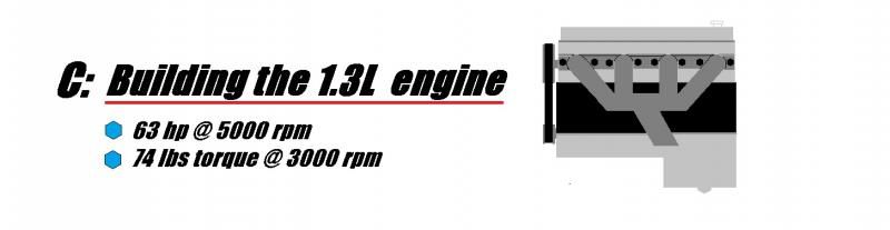
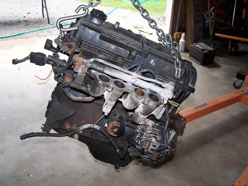
For those not familiar with my B3 Miata, here is a brief overview. The B3 project is my solution for sporty two passenger lightweight RWD commuter car. The original 1.8L engine was swapped with a 1.3L engine from a Ford Festiva. The car has been trouble free for over 40K miles and has delivered an average of 45 MPG during the daily commute.
My goal is to develop a tune that will allow the car to achieve 50+ MPG without sacrificing or suffering.
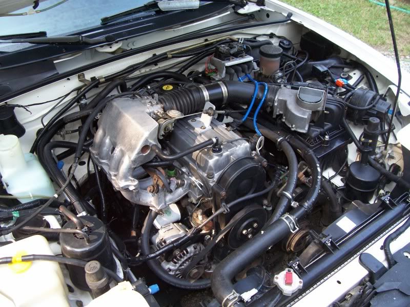
63HP B3 looks at home in the Miata engine bay.

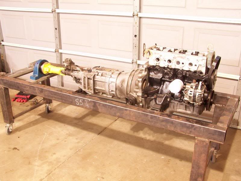
The Dyno.....
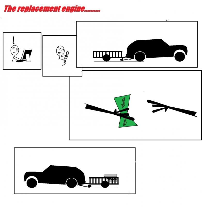
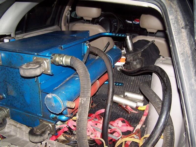
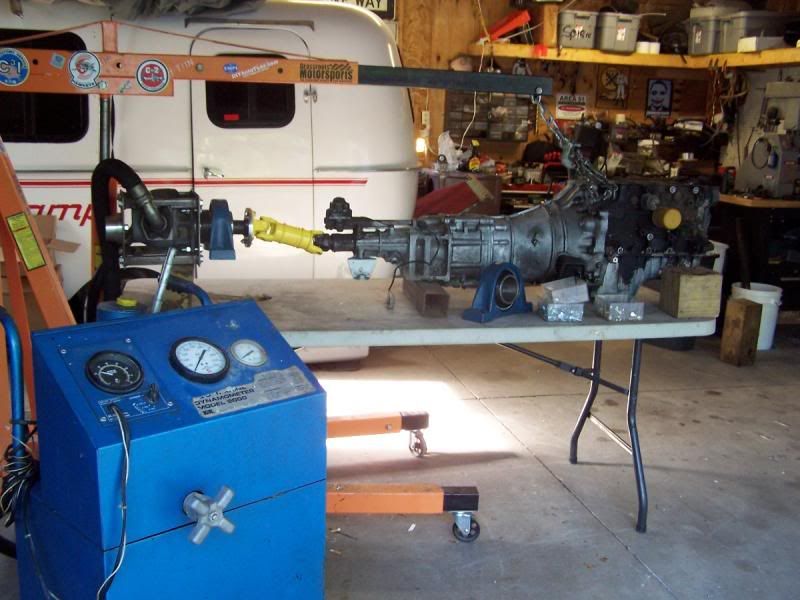
This dyno is made for marine engines and is able to absorb over 200 HP. It's basically a hydraulic pump with a controlled orifice. The bulk of this machine is the reservoir tank, which holds about 20 gallons of fluid. I spotted this treasure on CL for $425.00. I grabbed a friend and took a road trip up north to give it a good look over. The dyno looked great and was worth the $425, but I offered $375.00 and a deal was made. ($625 left in budget)
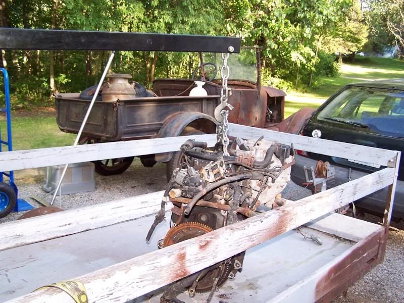
Getting this sucker home was somewhat of a challenge with my Saturn wagon. The dyno certainly fit in the wagon, but only if it was laid on its side. The problem is the dyno appeared to be leaking....
I have never been kind to my Saturn and was not about to start ... this trip will take its toll on the poor car. About half way home, I stopped for gas. While filling up, I noticed a puddle developing under the car. .... I paid cash for the gas and quietly slipped into the night, no doubt leaving a trail of hydraulic fluid in my wake.
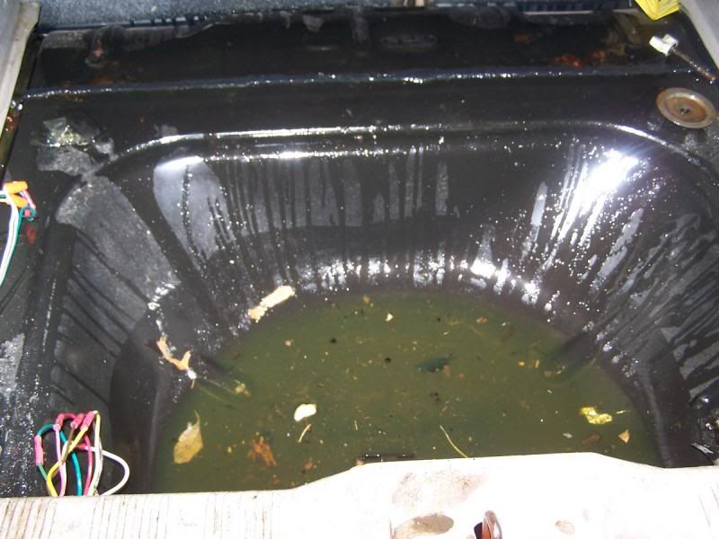
To date, I have recovered over three gallons of fluid from the interior of the car. I just drill holes in the floor and let it drain into a bucket. ... it could be worse.
Stay tuned!


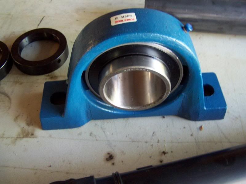 .
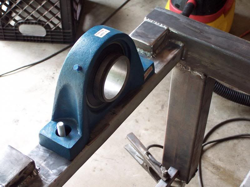
One of the two El-Cheapo pillow block bearings. $9.95!
.
.
One of the two El-Cheapo pillow block bearings. $9.95!
. 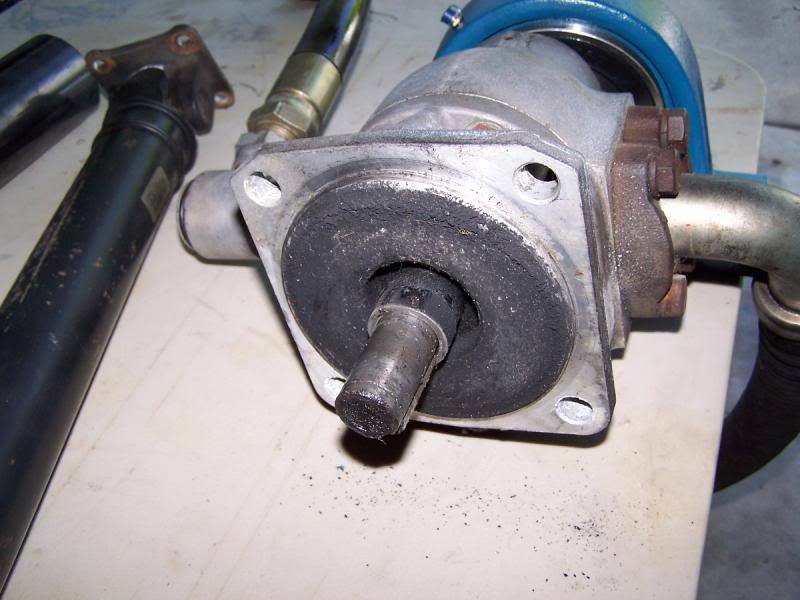 .
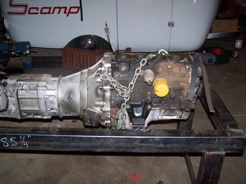
Here is the hydraulic pump that will act as the PAU.
.
.
Here is the hydraulic pump that will act as the PAU.
.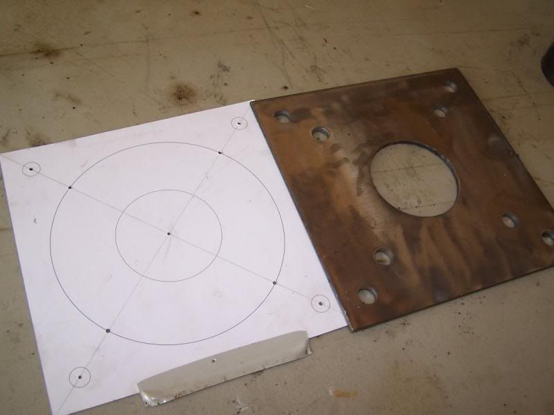 .
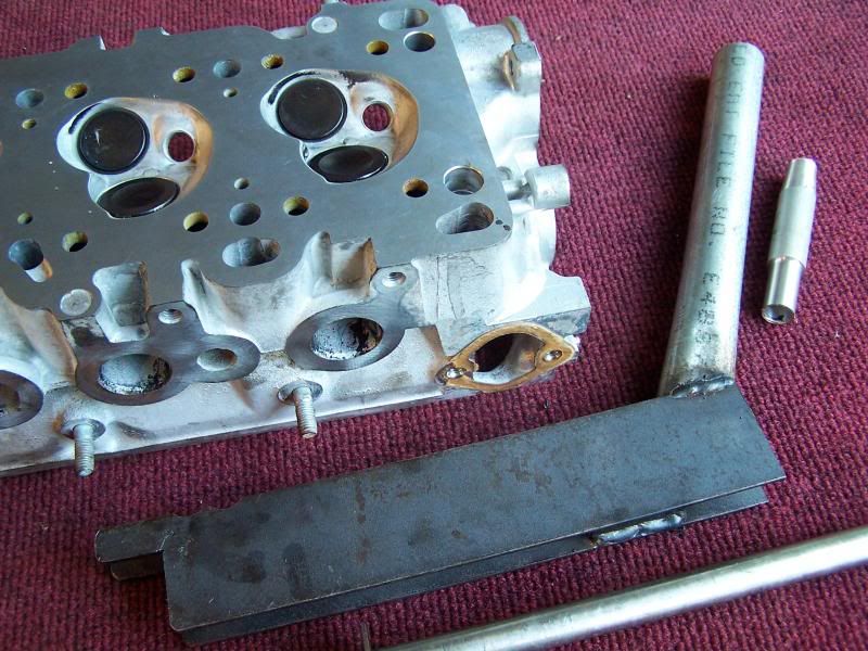
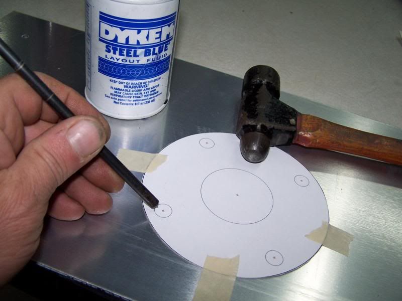
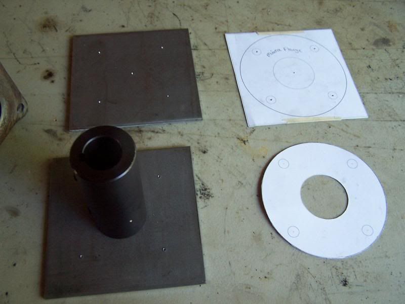
I started off making a template of the front of the hydraulic pump and transferred it to a 8x8 steel plate. Making templates is easy if you know how. I'll show you a quick and dirty cheat on templates in the next section.
.
I started off making a template of the front of the hydraulic pump and transferred it to a 8x8 steel plate. Making templates is easy if you know how. I'll show you a quick and dirty cheat on templates in the next section.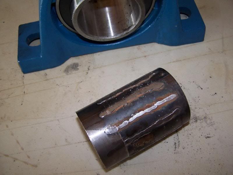
 [/URL]
.
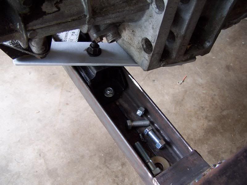
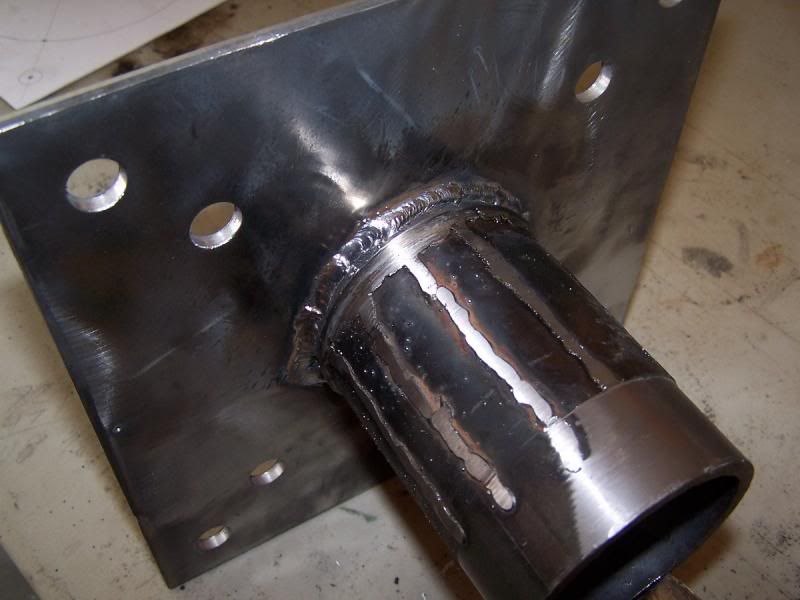
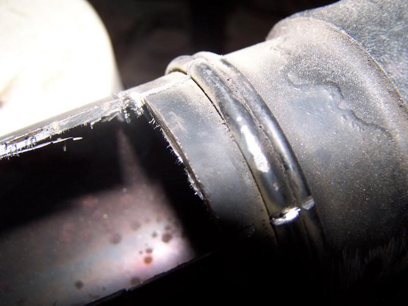
the pipe was then welded to the previously fabricated flange.
.
[/URL]
.
the pipe was then welded to the previously fabricated flange.
.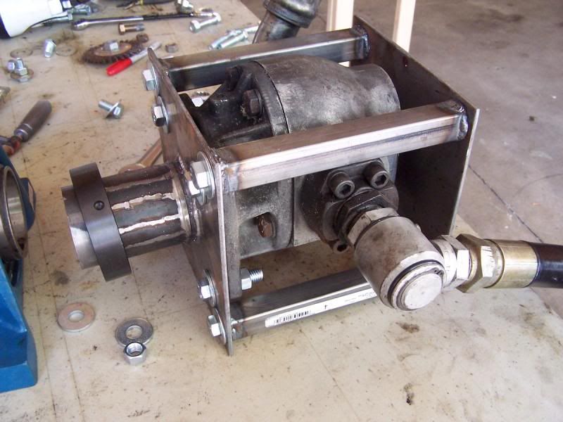 .
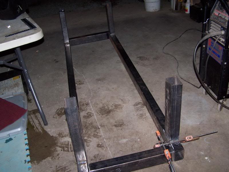
The pump lacked any sort of mounting surface on the rear so a removable cage was fabricated.
.
.
The pump lacked any sort of mounting surface on the rear so a removable cage was fabricated.
.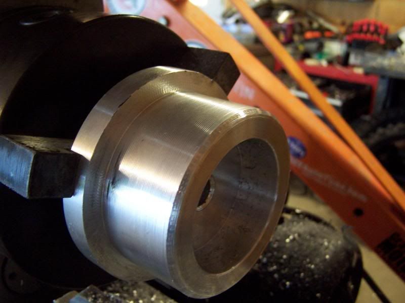 .
A hub was fabricated to support the rear of the pump. Pictured is half of the hub, the other half missed its appointment with the camera.
.
.
A hub was fabricated to support the rear of the pump. Pictured is half of the hub, the other half missed its appointment with the camera.
.
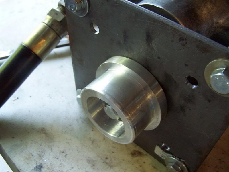 .
rear hub mounted.....
.
rear hub mounted.....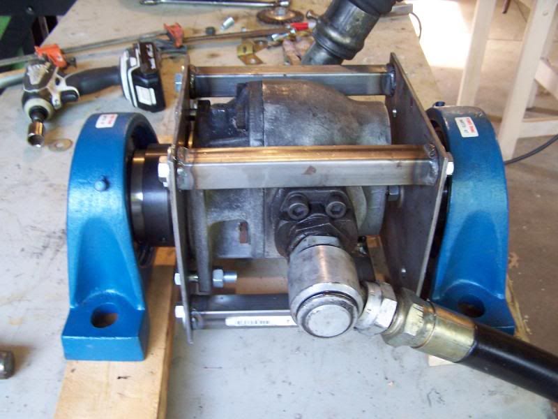 .
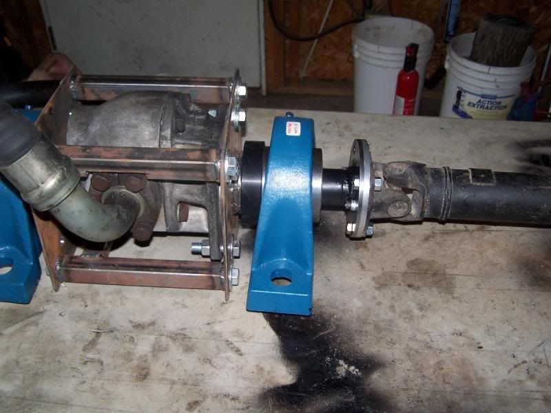
The pillow block bearings were test fitted to the PAU and the whole assembly moves with ease.
.
The pillow block bearings were test fitted to the PAU and the whole assembly moves with ease.


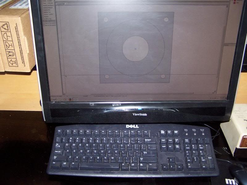
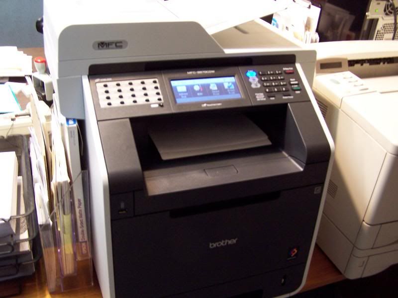 Distract the office manager long enough to get a useless picture of a printer spitting out the drawing....
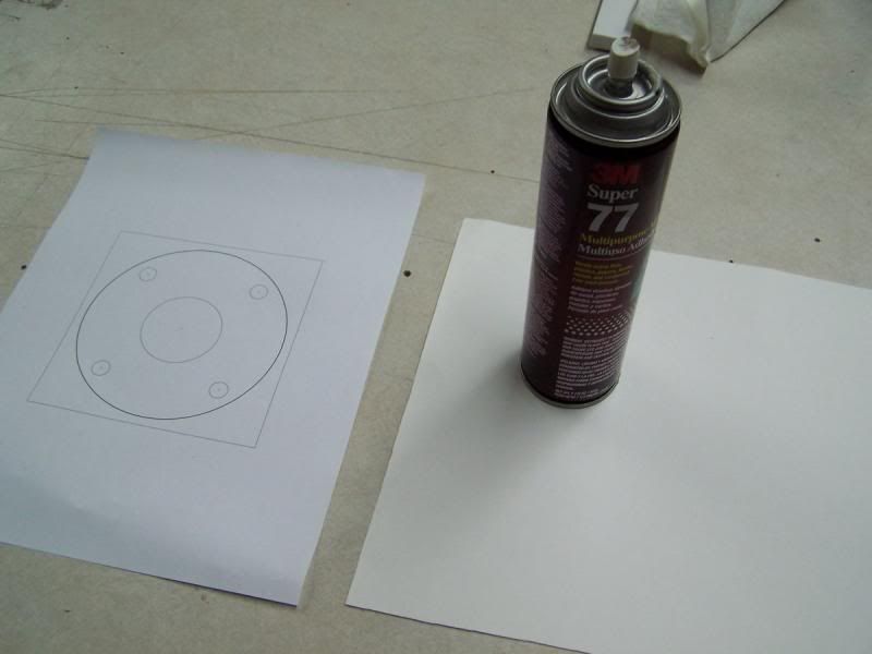 Spray the back of the drawing with artist achieve and affix to a piece of poster board.
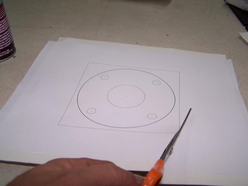 Cut template down to a manageable size.
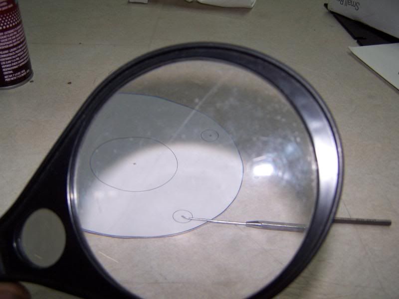
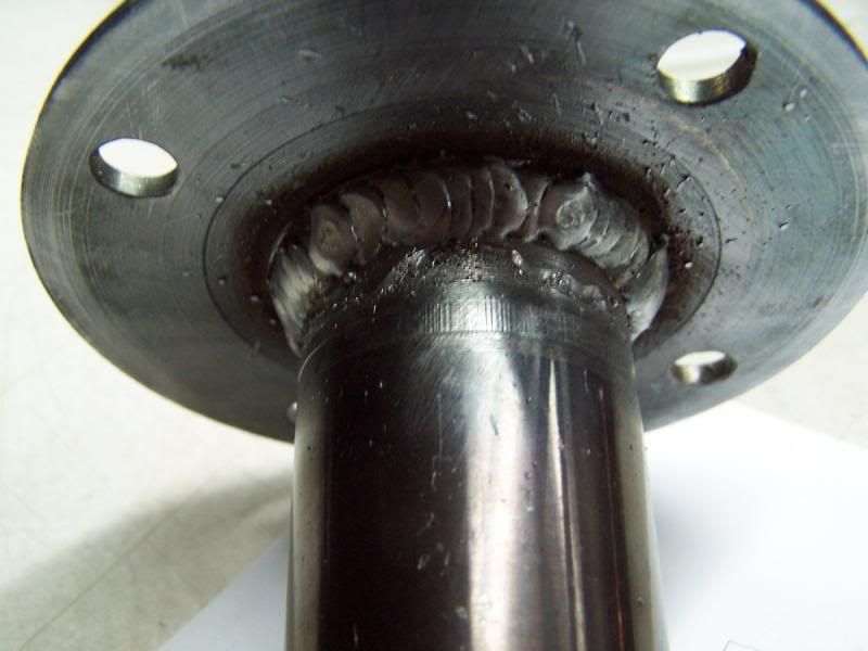 Welded!
 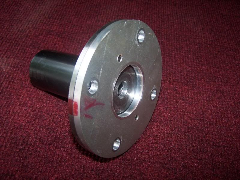 Secondary hub-centric flange mounted to adapter.
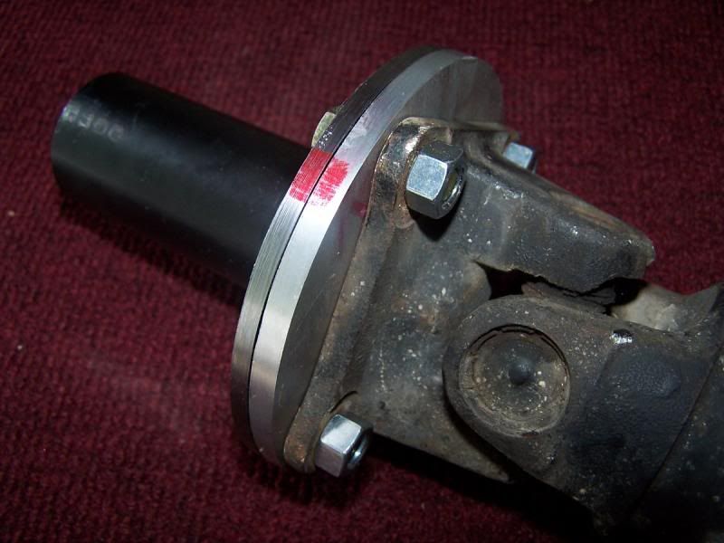
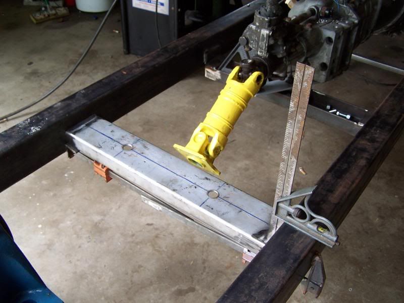
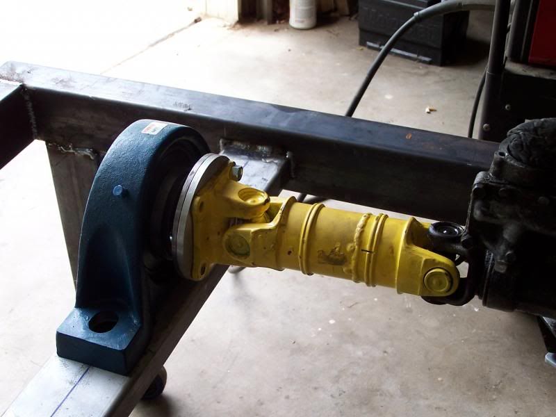
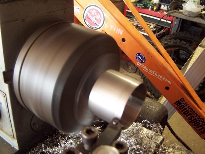
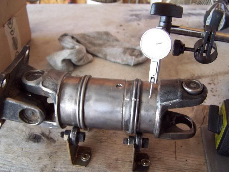
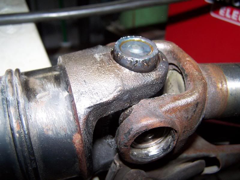
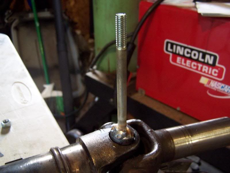
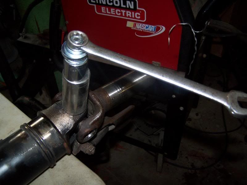
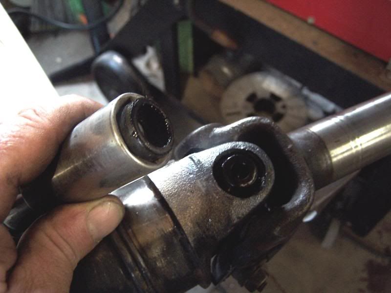
 Driveshaft test fitted to pump assembly.
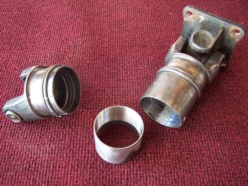
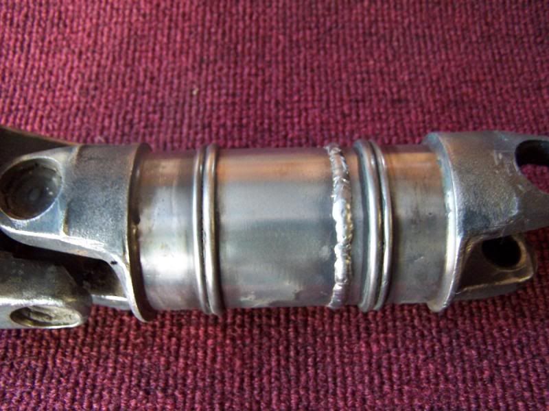


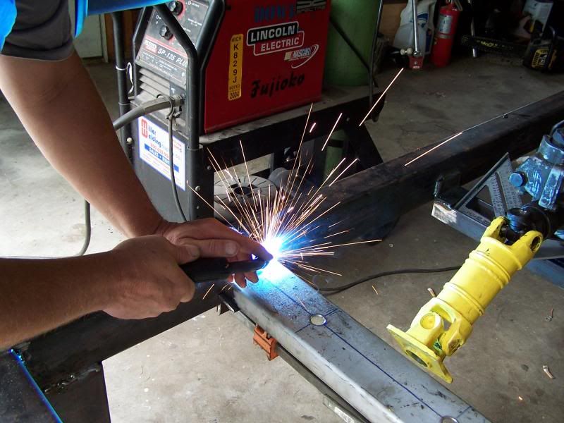
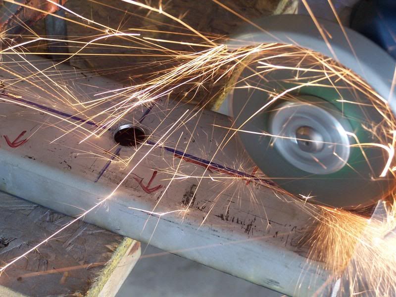
 cut, weld..... then light off some bottle rockets while the steel cools off.