


In reply to Curmudgeon: If you use a female heim joint to replace the rod end on the rack, no shortening required. Just have to drill the taper out of the arm.

In reply to Curmudgeon: If you use a female heim joint to replace the rod end on the rack, no shortening required. Just have to drill the taper out of the arm.

I thought about that, but there's two problems: if the rack is not shortened it won't fix the stock bump steer. Also, the Miata outer tie rods are angled which is part of how the engineers got the steering curve as neutral as they did. It's simpler and the outcome is better if the rack is shortened, moved back and raised.

Cool project and great work. I don't know if your aware of it but there is (IMO) a pretty cool retro body for the Spitfire.
 images
That's really cool! Looks like a D type and an E type had a baby that's not fully grown. I better not show that to my buddy. ![]()

Curmudgeon wrote: Hokay. Front suspension real work commences. The idea all along is to keep the wearable parts easily sourced 'off the shelf' and easily replaced, as much as possible. This will keep the car from being off the road while fabricating some weird one off part, if something breaks. So there's some adaptation involved. The GT6 upper ball joint won't fit the Miata upright, the shaft's too big. It's also tapered. Can't just drill the damn thing out.Tapered reamer to the rescue!
Now it fits.
The Miata lower ball joint comes nowhere near fitting the GT6 control arm. Some fabrication is in order.
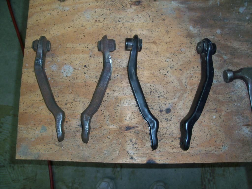
Closeup of the tip of the control arm:
The bolt hole for the ball joint is in the same place as the GT6 trunnion bolt. But the control arm is actually longer. How is this, you ask? The Miata ball joint pivots 1" from the bolt hole, the Triumph pivots at the bolt hole. So the modified arm is actually longer even though the hole's in the same place. This is very important, because it affects scrub radius and the motion ratio which affects the wheel spring rate and also the wheel travel. Triumph upright in place:
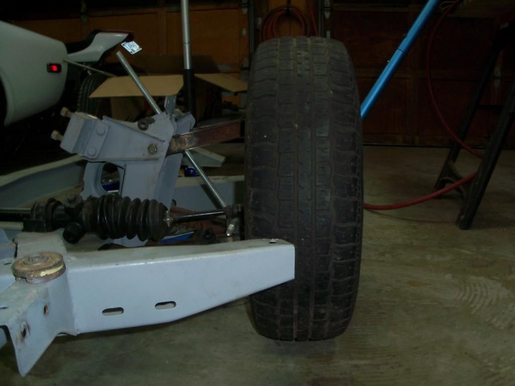
Miata upright in place:
The lower shock mount has been sorta 'roughed' in, it still needs to be boxed in to prevent bending. The final work on that will come after the shocks have been sourced and the fit is 100% verified correct. There's still some positive camber which has to be fixed. This will mean moving the upper ball joint closer to the car's centerline, which will have some other effects. More on that as it happens. The next step after that is shortening the steering rack.
Sometimes it's just easier to buy Off The Shelf?
http://www.canleyclassics.com/?xhtml=xhtml/product/adjustabletopwishbone.html&xsl=product.xsl

Can you shim the lower arm outward? On the early TR4s the camber fix is TR4a - TR7 lower arms and brackets and shim them in or out - although some racers shorten and box the upper arms. I've also heard/seen that chrysler minivan tie rod ends have a good angle to them for triumph racks - as well as common and cheap.
The idea is to shorten the upper control arm for zero camber with the lower arms parallel with the ground, then shim the lower CA's out to add static camber. The shorter upper CA will make the camber curve more aggressive which will help keep tread on the road.
Those Canley arms are really nice. But 178 British pounds = 290 American dollars.

Wow, I never knew you had skills like that. Makes me want to buy a GT6 and hand it to you with a bucket of cash.
Actually, on a serious note (I don't ever have any money, any talk otherwise is surely in jest) a buddy of mine (volvoclearinghouse on here) and I were talking several years ago about a cottage industry where you set up a domain much like the modern OEM websites, set up a configurator so they can choose what options they want and everything, but instead of new boring cars, you do this with GT6s (we were going to do it with Ford/Chevy/Dodge trucks (diesel, gas, lifted, lowered, etc). This way you can get some customers to really see what options there are, get them to drool a bit, and then get some customers. Then you quit your job, and post over on the 'dream job' thread as the guy who sells refurbished GT6s for a living.
As I work on this I keep thinking I might see if I can come up with a sorta bolt on kit for doing this. I would think there would be a market for it, seeing how many Spitfires and GT6's are out there. But that's a ways in the future.

In reply to Curmudgeon:It is nice to see people willing to biuld rather than buy!I used the miata front spindles and fabed up my own control arms.In the end it was cheper than trying to modify everything else.I always loved the sixes I just don't fit in them too well.

Curmudgeon wrote: As I work on this I keep thinking I might see if I can come up with a sorta bolt on kit for doing this. I would think there would be a market for it, seeing how many Spitfires and GT6's are out there. But that's a ways in the future.
I don't know... As I look at my own GT6 I wonder where and how to relocate the rack without relocating the engine as well. Fine if the plan is to build something like FIS6, but less so if the desire is to keep the car somewhat original.
If/when I'm able to build a roto-Spit then all bets are off, although I also wonder if just building a dedicated tower would be easier?
Curmudgeon wrote: The idea is to shorten the upper control arm for zero camber with the lower arms parallel with the ground, then shim the lower CA's out to add static camber. The shorter upper CA will make the camber curve more aggressive which will help keep tread on the road. Those Canley arms are really nice. But 178 British pounds = 290 American dollars.
Sure, got that.
But looking at the solution, seems like it offers a good approach for the 'creatively endowed'.
Basically it's 6 parts:
1 x curved steel tube
2 x short steel tube for bushing
1 x steering tie rod end (origin inknown, but same taper as the Spitty top ball joint)
1 x threaded steel tube for tie rod
1 x jam nut for tie rod
You might even fangle just a threaded tube, welded to the modified ends of the current A-arm.
Screw the tie rod end into the threaded tube, adjust to get desired camber, tighten jam nut.
Voila!
The GT6 motor would have to come back a LOT to get out of the way of the steering. I think some sort of parallelogram linkage would probably work if the the engine was to stay in the same place, but that means a recirc ball steering box or a really short rack which operates on one side of the linkage only thus opening a whole 'nother can of worms.
Since the guy who owns the car is not wedded to the GT6 engine, it's a perfect setup to make the suspension first then make the power unit work with that.
The Canley arms could certainly be duplicated and yes that was considered but with a rod end. In the long run, it's quicker to set the camber by shimming the lower control arm brackets and that's what drove this setup: ease of adjustment plus easily sourced parts. I gave serious consideration to a setup similar to the circle track upper arms with two turnbuckles etc but there's not a whole helluva lot of room plus we start getting away from that 'easily sourced repair parts' thing. That's why I did the Toyota trans swap in my J-H by having the flywheel redrilled; now I can walk into AutoVanceZone and buy a Toyota disc, PP and release bearing for my oddball.
On the rear, it may wind up with an eccentric cam on the outer end of the upper arm.
Yeah, I'd say the positive camber is a bit excessive.
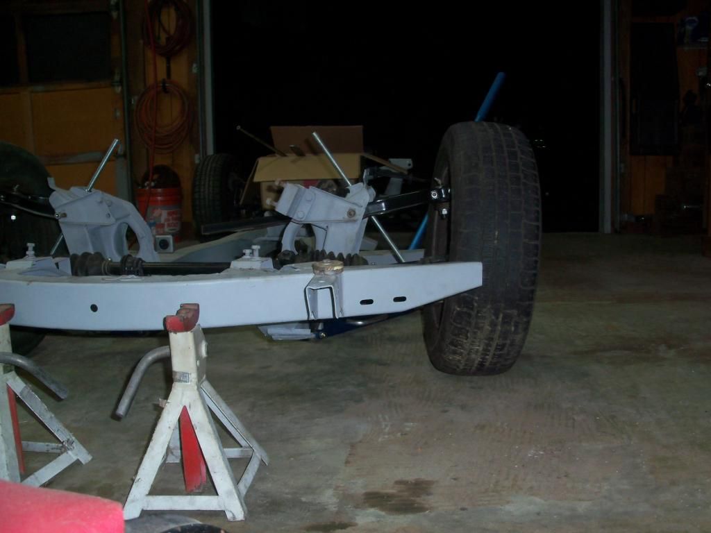
Shortened the stock upper control arms 7/8".
Now we have a decent start point for alignment.
I took a couple days off to get the Curmudgonling's ride cleaned up, she's out of town and does not know about it yet. I plan to record her reaction. ![]() Here's a small sample of how nasty it was inside:
Here's a small sample of how nasty it was inside:
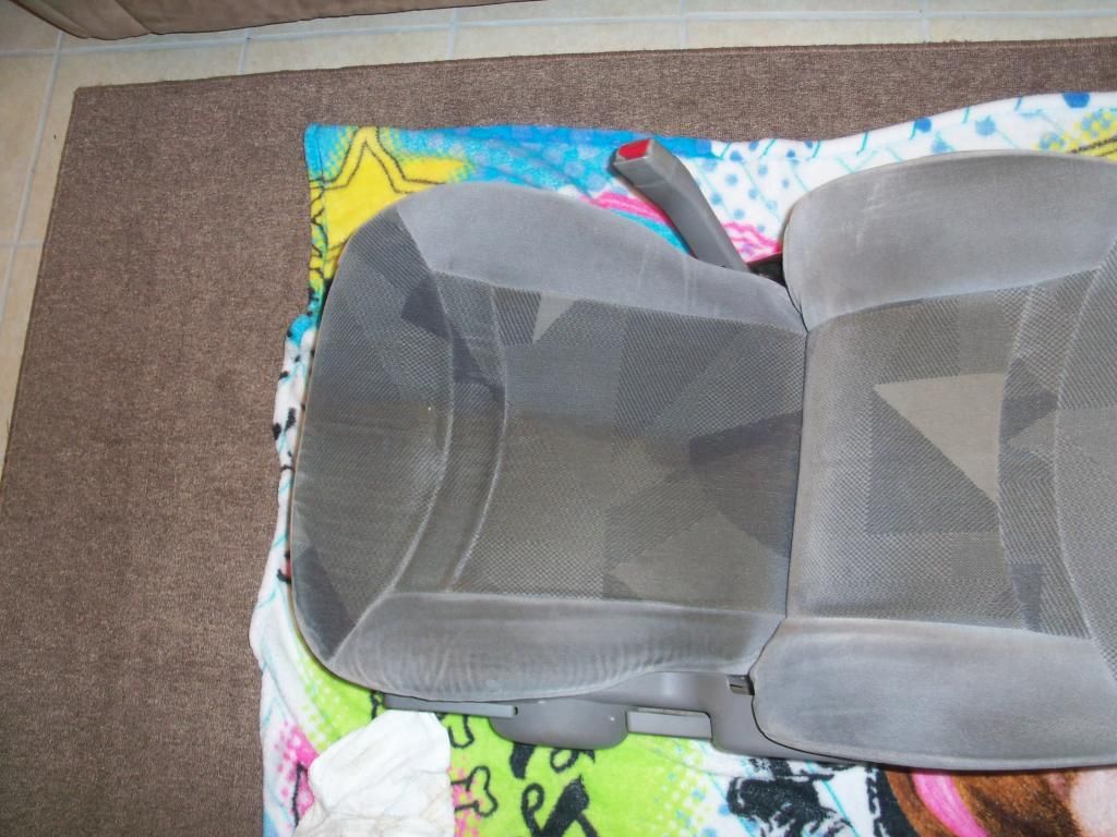
Driving it home made my skin crawl. I had to dump a bunch of interior panels in the bathtub with hot water to get the scuzz loosened where I could scrub it off, the carpet had to be pressure washed and it's still drying in the sun.
Next GT6 project step: shorten and reposition the steering rack.
Some folks have suggested just adding more shims at the bottom to fix the camber.
Problem with that is the length of the attachment stud welded onto the wishbone mounting bracket.
You simply run out of threads after 6-7 shims. And that's one of the pieces that you don't want to come loose.
You can use a low profile Nyloc to gain another few shims, but 1/2" or so is the limit.
It's possible to open up the offside hole, and use a shouldered nut (like a mag wheel lugnut).
But the stud runs through an internal spacer, which keeps the chassis walls from collapsing together when you tighten the nut.
So you'd need a shortened spacer, or maybe a steel tube big enough for the shank of the shouldered nut, welded at the offside hole, and maybe ground flush.
Curmudgeon chose a simpler solution by shortening the top arms.
Right, the idea was to start out at 0 degrees camber with no shims. Now I can start stacking shims to get more negative camber. A side benefit of the shorter arms is the more aggressive camber curve means it doesn't have to have a lot of static camber, that's important on a street driven car which this one will be.
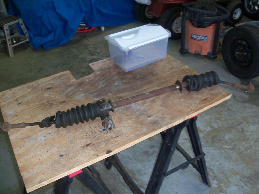
Shortening the rack, oh what fun! This has to be done before any further front suspension work is possible. Important dimensions: the inner rack winds up at 20.625" long as measured from end to end of the threaded parts. This puts the center of the inner tie rod balls about 1/4" outboard of the lower control arm inner pivot when there are no camber shims added. That way when shims are stacked to add some static camber the ball is almost perfectly centered with the inner pivot, which is a big deal when fixing the awful stock bump steer. The housing is 15.500" long overall. The drivers' side of the rack has a counterbore of .625" so the true housing dimension is 14.785". This leaves a total travel of 5.750" but when I account for the thickness of the tie rod nuts it becomes 4.875". This is less than the stock Spitfire rack travel, but there's another thing to keep in mind: the Miata steering arms are shorter than the Spitfire meaning a higher angularity for a given amount of travel. The Spitfire arms are 4.500" and the Miata arms are 3.875". This is measured from the center of the spindle to the center of the tapered hole for the tie rod.
Subject before surgery:
Point of no return. The last rack I shortened was cut in the middle and it warped a LOT during welding, it was really tough to get it straight. So I decided to try something different here, I cut it toward one side. The idea is the warpage will stay to a minimum. No pics, but I beveled the ends of the two pieces, then clamped them in the 'V' of a piece of angle steel, then burned 'em together, making multiple passes. Once the welding was completed, I used a bench grinder to knock the weld down then used a die grinder and grinding discs to smooth it out. The key is to take your time and pay very close attention! My theory worked, the warpage was at a minimum. I put the welded section on top of two pieces of steel, then smacked the hell out of it with a big ol' brass drift I got from somewhere or other. I kept doing this till it rolled cleanly on a glass tabletop I have on my back porch. It was only off maybe .010 or so to begin with, the first one I did many moons ago was bent like a damn banana and took some serious wailin' to straighten.
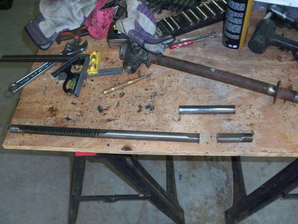
Once this was completed, I sectioned the rack housing and welded it back together. For some stupid reason known only to Triumph, the housing is not the same ID all the way down, it's a smaller diameter on the end where the bushing is pressed in for about 3". That means cutting a piece out then welding the end back on. Not difficult, just a little aggravating.
When test fitting the inner rack to the housing, it has to be a easy slip fit all through its travel. If it has any bind at all, the steering wheel won't return quickly and believe me that is aggravating in an autocross.
I kept after a few small spots that were binding, then flipped the rack bar around and ran the teeth through the bushing a few times to remove a few high spots. It now slides nice and free with maybe .006 of 'wiggle' clearance, the grease will account for most of that.
The completed rack:
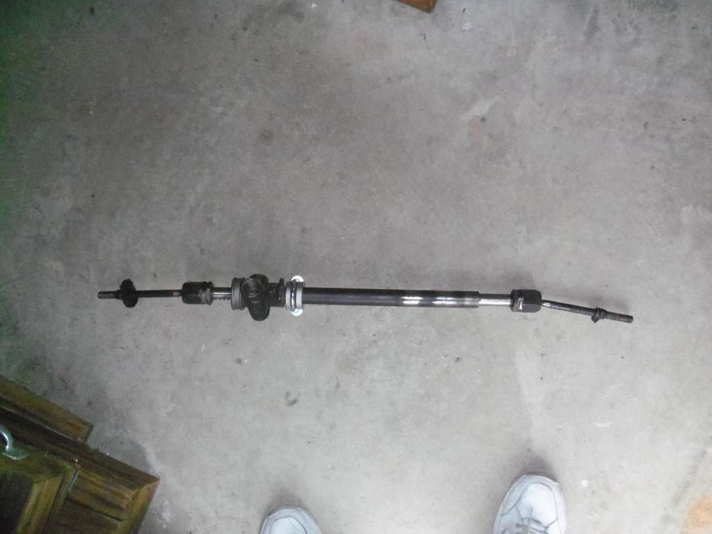
Hard to see just how much shorter the modified rack is than the original, but here they are.
Next step: modifying the 'turrets' for rack clearance. That's necessary because for the Ackerman to work out properly, the steeing rack centerline needs to be about 1/2" behind a centerline drawn between the outer tie rod hole centers that are drilled in the spindles. The stock rack mounting pad on the drivers' side needs some mods too, it needs to be extended about 2" toward the center of the car so the rack housing can be properly centered in the frame. Once that is done, I can get accurate measurements for the hybrid Miata/GT6 inner tie rods. And once THAT is done I can fab a lower steering shaft extension. I'm getting tired just reading all this. ![]()
Gunks wrote: In reply to Curmudgeon:It is nice to see people willing to biuld rather than buy!I used the miata front spindles and fabed up my own control arms.In the end it was cheper than trying to modify everything else.I always loved the sixes I just don't fit in them too well.
Having seen your handiwork in your build thread, that's high praise indeed. Thank you!
oldtin wrote: Can you shim the lower arm outward? On the early TR4s the camber fix is TR4a - TR7 lower arms and brackets and shim them in or out - although some racers shorten and box the upper arms. I've also heard/seen that chrysler minivan tie rod ends have a good angle to them for triumph racks - as well as common and cheap.
Any idea what year, etc to look for and are they angled? The Miata outer TR end is angled, that moves the outer pivot further out which effectively makes the tie rod longer so it will more closely match the length of the lower control arm which is a big deal for bump steer reasons. (Whew. ![]() )
)
If I could find a 'bolt on' option it would save having to make hybrid tie rods.
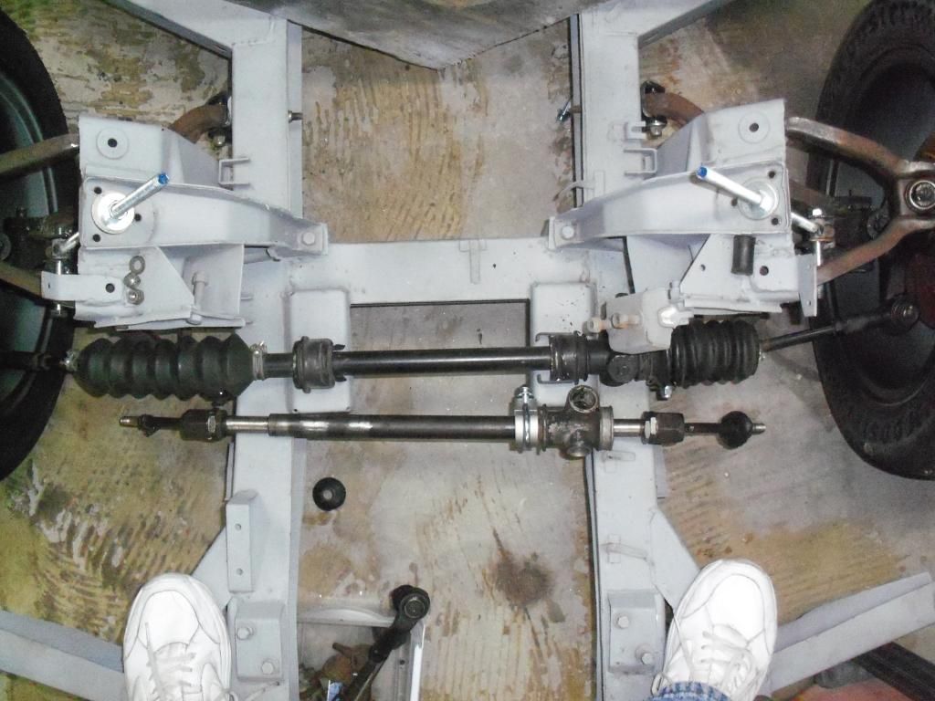
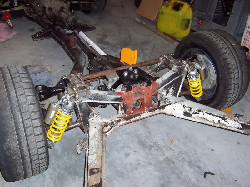
Ran into the problem of not being able to lower the rack enough to use the Miata tie rod ends unless I cut a hole in the frame and that entails a tremendous amount of fabrication. I checked carefully, the center of the outer tie rod is within 1/8 of a line drawn between the upper and lower ball joint centers. This means I can put a tie rod on top and still have a good bump steer curve. So that's what I did. Got the rod ends from QA1, they have a total of 65 degrees travel which leaves a cushion if the suspension is at full droop or full bump. I used two sets of GT6 inner tie rods to make a set that are 9" long from the tip of the ball to the tip of the thread. The steering rack is 1/2" behind the centerline of the outer tie rods, so tbat fixes the goofy Ackerman. Mostly completed rack installed for final test fit:
The rack needs to come up 1/4" so the tie rods will be parallel with the lower control arm, that's another bump steer thing.
With the steering mostly completed (need to set the block in place for a test fit) it's time to move on to the rear suspension. Parts and steel are on the way!

Can you show a picture of the rod ends you ended up going with? Maybe the info on them? I'm in the middle of restoring a 67 GT6. I had already planned on using a miata IRS but now I think I will follow your lead on the front end as well.
Here's a link to my build if you get board: http://www.theturboforums.com/threads/365625-1967-Triumph-GT6?p=1862303#post1862303
jmc14 wrote: Cool project and great work. I don't know if your aware of it but there is (IMO) a pretty cool retro body for the Spitfire.

It's BEAUTIFUL
In reply to MKI_GT6:
The rod ends are QA1 high misalignment pieces. Their number is PCYRF8T.
http://www.qa1.net/qa1_motorsports/circle-track/rod-ends/2-piece/pcyf-t-series-chromoly-steel.html
They have a total of 65 degrees of misalignment, the Miata steering arm is angled 22 degrees from horizontal, leaving 10 degrees of misalignment. That's enough travel left for the suspension to have a lot of 'droop' without the ball bottoming on the race.
I just finished 'roughing in' the rear lower control arms and will be posting pics of all that fun stuff soon.
Checked out your build, that's pretty cool! That motor was on the short list for this project. I would recommend that you not try to adapt the Miata subframe in the rear, it's way big in every dimension compared to the GT6 stuff and would involve massive body surgery. That's why I am building another homebrew IRS like I put under the Abomination, my rotary Spitfire.
I'm unfamiliar with your previous car. Can you give me the run down on what you have planned for the rear?
That was my $2006 Challenge car, it now belongs to Toyman on this board. It's the one with the red stripe in this picture.
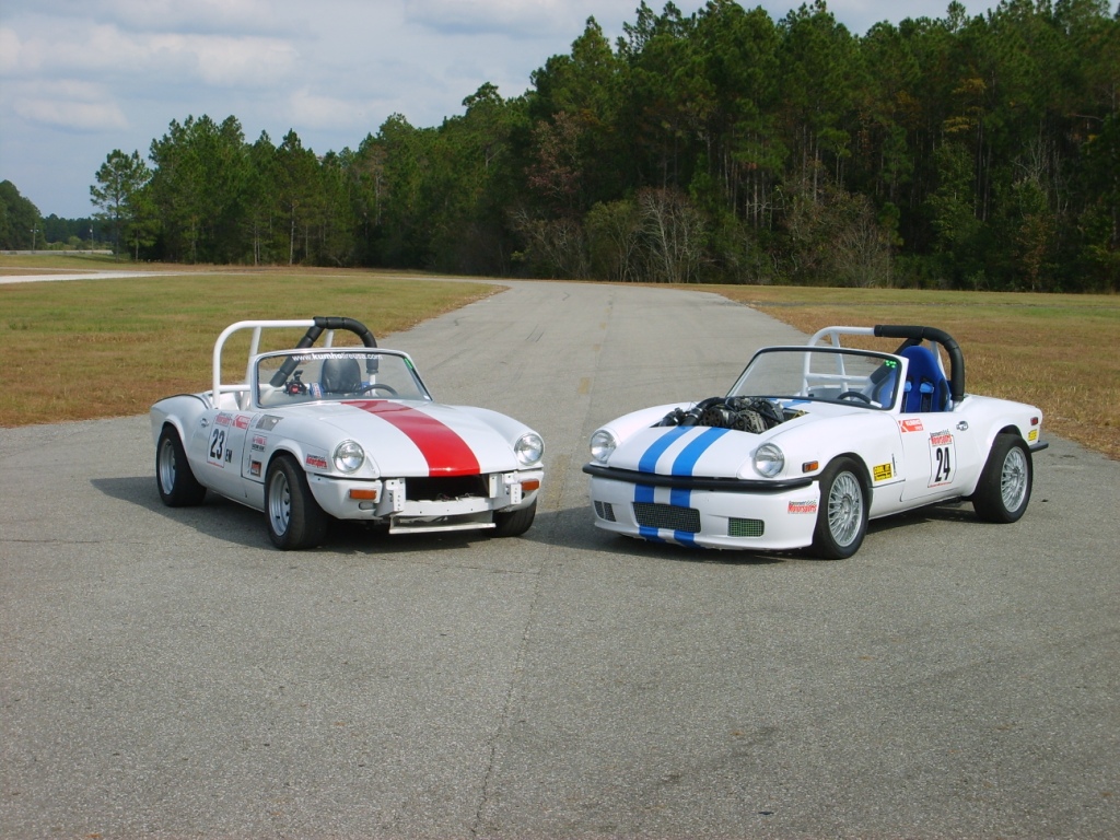
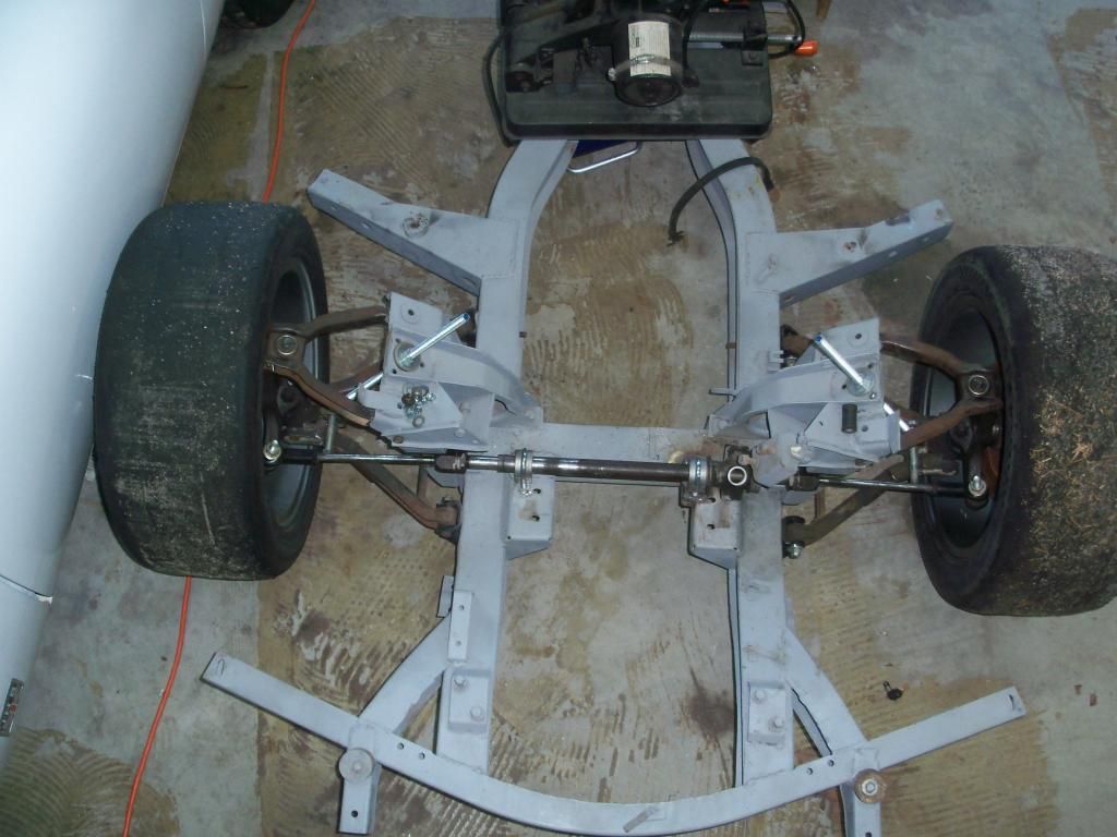
I did not document that build very well but I did snap a few pics. Here's two pics of the rear suspension setup, I plan to reproduce it with this car with some minor upgrades like easier rear camber adjustment. The diff in these pics is a 2nd gen RX7 'long nose' which is very similar to a Miata diff which will be used in the GT6.
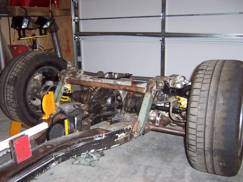
The lower control arms are completely hand built. The uppers are much modified Miata parts, the rear suspension uprights and the brakes are Miata parts too, specifically from a 1.6 engine car. That's so the brakes will fit inside 13" wheels.
You'll need to log in to post.


