
HalfFast said:
There was a guy with an obnoxious Rx7 that has an add on muffler he used in the paddock and when at home.
Another more expensive option is a supertrapp tip. Easy on and off, and small enough to do what you're doing
Supertrapp muffler
I'll see how the one I ordered fits and sounds. Hell, I may just leave it on there. I took another look at the routing and I almost wish I had gotten one with an offset inlet and outlet.
*************
I pulled the trans back out. I should be able to install the insert without removing the bell housing. Once I remove the starter, there's plenty of room to turn a tap wrench. It's the hole with the black arrow. The red arrows are the bolts that mount the bell housing to the engine. You can see that the flange of the bell housing is sandwiched between the engine mount and the engine.

So, just in case I do decide pull the bell housing, which I'd need to do to change the clutch, does the GRM world think it would be okay to put a 2 x 4 under my oil pan and support the engine with a transmission jack? The engine would still be supported somewhat by the front engine mounts. It's a little hard to see in this pic but there's the oil pan.

I took another look at the bolt hole issue. Below is the lower left hole. I can see a ridge of built up crud where the bolt threads end. Beyond that, I can see that the threads continue for at least half an inch; possibly more. These are through holes. Then I looked at how much the original bolts were protruding through the mounting flange of the transmission. They were 2" bolts and only getting between 1/2" and 5/8" of thread engagement.  So I re-tapped all the holes (1/2"-13) to the full depth of the tap and swapped them for 2 1/2" bolts. Transmission is back in and I'm calling that done. No need for an insert. The lower right bolt that originally stripped felt good and tight. But I'm now thinking I might try to put a 3" bolt in that one just to be sure because it's really only getting 1/2" of thread engagement again because the first 1/2" was stripped. I'm sure there's an extra half inch of threads in the hole.

Everything underneath is buttoned up again. I ended up cutting a 3" bolt down to 2 1/2 and threading about 5/8" of the unthreaded portion of the bolt. I rechecked the bolt hole for depth and there was plenty of space. I probably could have used the 3" but I didn't want to push my luck. I feel a lot better using the longer bolts.
Moved on to learning more about my fuel filter. The blue cartridge on top of my fuel cell is definitely the fuel filter.

Suppliers of this type are not all that good about making "fuel filter" searchable on their sites so it took me a while to find what I was looking for. Apparently, these are "log style" fuel filters. The canisters are all the same except for the AN fitting sizes, as far as I can tell. Mine is a 8- fitting. The cartridges are 8" and come in either paper or SS mesh. Mine is SS.
The filters are directional. They should only go one way into the canister:

Mine, of course, was installed backwards. The SS cartridges are supposed to be washable. I flushed mine from the inside out with the only spray solvent I had which was some mass-flow cleaner. I didn't see any noticeable sediment or dirt coming out. Calling it good enough, unless someone has more input. I also ordered some clamps to attach it to the frame instead of zip ties.

This would be the correct orientation:

Just need to vent...the layout of things mounted to and going through the firewall SUCKS!! More later.
Maybe the PO changed his underwear by turning them inside out?
jimgood said:
Just need to vent...the layout of things mounted to and going through the firewall SUCKS!! More later.
So, about that...
There are other issues but his one just chapped my a$$ the other day because I was trying to make sure all the AN fittings were tight. There is oil residue everywhere under the car and on the firewall. Some of it appeared to be concentrated around the oil return where it goes through the firewall but it's hard to tell if that's the source. There's also a lot on and around the starter relay and the oil inlet coming through the firewall. There's some on the engine block below the rear of the valve cover so that may be a source as well. But that's also in the vicinity of the oil inlet.
The thing that bugs me is that the fuel line, oil inlet and starter relay are so close together than it's not possible to get a wrench on the oil line fittings. Why!!!??!! There's plenty of room on that firewall. There's no earthly reason that starter relay had to be right there. So another item on the To Do list will be to move that relay to a more accessible spot, probably in that wasted space behind the coil.

I got some strap mounts for the fuel filter and mounted that a little better. I used nutserts on the square tube underneath it to bolt the straps to. I wanted to put the nutserts on top of the tube but there wasn't enough headroom for the tool. One nice thing is that there is so much room in the rear fender well that I could just undo a couple of the body braces and I could sit on the floor with my torso inside the fender well to work on it. 

One of the other things I'd like to address is the wiring and gauge layout. First, the positive terminal on all of these switches is connected via a common bus bar. This is barely contained in the area between the switch panel and the cage bar. I don't know how dangerous this really is but it doesn't seem like a good practice to me, unless the switch panel is boxed in where one couldn't accidentally get a tool in there. Also, the wiring is a bit untidy for my tastes. I want to clean that up.

The gauge layout is weird. The most important gauges are mounted directly to the firewall, 45" from my face. A bit far for my eyes. So I plan to make a console of sorts and mount those four gauges where I can see them through the steering wheel. I have a cardboard template drawn out for that.

I'm planning on running two fire system pulls; one for me and one for EV. Same for the battery cut-off. I don't recall how the fire system pulls are attached to the bottle and how two would work. I guess I'll cross that bridge when I get to it.
I might also move my fire bottle. It's currently mounted behind the seat but I'd like it to be more accessible. That's a bigger job as I'd need to reroute the lines for the nozzles so I might save that for next winter. I don't think there are any lines/nozzles for the engine bay so I'd like to address that too.
The Tommy Boy thread got me thinking more about how to make my front clip and front half of the greenhouse removable. I think the front clip is going to be relatively simple. Looking at the fender from the outside, it is joined to the cowl (which is part of the front greenhouse) and to the door panel. There is a good bit of overlap between the fender and the door panel. Feels like about 2-3 inches. I'm thinking one or two Dzus fastener at the top to join to the cowl and 3 or 4 along the side to join the fender to the door panel. There is one point where the door panel is sandwiched between the fender and cowl. That might be too thick for a Dzus but I'll have to see. Worst case, I use a screw there.
The rocker panel will have to be cut to match the edge of the fender but the two halves can remain riveted to their respective panels.

Below, looking at the inside of the fender, front to rear. I think the part I'm calling the firewall extension is seam sealed to the inside of the fender. I couldn't see any other means of attachment. This basically just blocks off the area between the A-pillar post and the fender. I think I would remake this piece so that it is permanently attached to the firewall and door panel. Would need to see how it all comes apart to know for sure.
What I'm calling the rocker pan could be cut at the same point as the rocker panel and remain riveted to the fender. I could add a tab or two on the frame rail and use Dzus fasteners to attach it instead of the rivet that now holds it. It would be best to overlap it with the remaining rear section so this might be another piece I need to remake. Interestingly, I can't find this part on the FiveStar Bodies website.

Here's what it looks like at the top inside the fender, where it joins the cowl and where the hood hinge is riveted. I would probably need to run a square tube across the engine bay at the cowl to attach the fenders to one another.

Sorry for jumping around so much but I finally remembered to take a closer look at my carburetor and noticed something I'm not sure about. Here are the fuel inlets on the passenger side. That's not the thing. Check the next pic.

On the driver side, there are the same ports but one is blocked off and the other is open. I get that the ports exist on both sides of the carb to accommodate different fuel line routing. But shouldn't both of these be blocked off?

In reply to jimgood :
I will suggest that it IS blocked off, just in a different way. If not, fuel would pour out. It may just have a pressed in plug. But I'd check.
HalfFast said:
In reply to jimgood :
I will suggest that it IS blocked off, just in a different way. If not, fuel would pour out. It may just have a pressed in plug. But I'd check.
Makes sense. Just seems weird that they're different. When I look at this pic of the same model carb on Holley's site, it's got two "plugs" and two threaded connectors.


BKO5
New Reader
1/19/23 10:06 p.m.
The fire wall extension is called a crush panel. Usually around .020 thick aluminum, riveted to the fire wall and seam sealed to the inner body. They have two purposes, to collapse fairly easily if the car should make light to medium contact while preserving the fire wall by not putting it up against the inner fender and to keep debris out of the interior.
BKO5 said:
The fire wall extension is called a crush panel. Usually around .020 thick aluminum, riveted to the fire wall and seam sealed to the inner body. They have two purposes, to collapse fairly easily if the car should make light to medium contact while preserving the fire wall by not putting it up against the inner fender and to keep debris out of the interior.
Makes sense. If I can seal it against the door panel instead of the fender, that should work just as well. We'll see. I'll meditate on it a while.
Back to the wiring...I have disconnected (or cut) and labeled every wire in the cockpit. I tried to compile a list of every electrical component in there and it's requirements (e.g does it need a switch, how much amperage does it draw, etc.). Then I spent an hour or so in Visio creating a wiring diagram. This plan will certainly change as I may have to combine a couple of components onto one fuse.
Depending on how long the run is from the fuse box to the components, I might use wire colors other than red for all the positive feeds. There isn't a component in the system, save for the MSD and the cooling stuff, that requires a wire gage larger than 14. Yet there were a bunch of 10 or 12 ga wires. There were also a few exposed positive connections that I can take care of, one of them hanging in mid air near the fuel cell (just two wires twisted together).
This is not a complete diagram (and my symbols probably aren't all technically correct). I was just trying to capture most of what's in the cockpit. The color of the wires going between the fuse and the load will likely change. I want those to be different for every component, where possible.

I still have to come up with a plan for a gauge console that I can live with. I'm no tinsmith but it will be something that's serviceable and looks okay. I've got the tach and 5 small gauges. I will leave a spot for a GPS speedo as I don't want to spend the cash on that right now.
Why a speedo? Is that for your YouTube channel 
HalfFast said:
Why a speedo? Is that for your YouTube channel
For my ego. 
But seriously, people always ask me how fast I'm going. I'd like to be able to answer without math.
Three hours in the shop this morning and all I have to show for it is this lousy bracket. Actually, I spent a lot of time in the seat trying to figure out gauge layout. My previous plan won't work because it would put the gauge pod right where my left knee needs to be when I'm getting in and out. It always ends up right in that corner where the steering bracket meets the dash bar. Thankfully, all I did was a cardboard template.
I decided to start with the tach. I couldn't put it behind the steering wheel because it was blocked out. Couldn't put it above the steering wheel because it would block my view of the rear of HalfFast's truck or jh36's Camaro. So this was the best option. Before it was about a foot further back and I couldn't reach it to adjust the shift light (which wasn't connected, incidentally).

Last night I was doing research on brake pads because I noticed my front pads were pretty worn down. These pads new have nearly a half inch of pad material. Now they're down to about 1/4". Still useable but not for long. And I'm also not sure the compound that's on there is any good. Like I've said earlier, slowing this thing down feels like I'm trying to stop my trailering rig.
For the amount of pad wear, there is nearly zero rotor wear. So I'm thinking these pads might be a street/performance compound. Because I had no idea how to look up pads for this car and since my front calipers are from Howe, I went to their site to see if they have pad recommendations. They do but it's buried in their catalog here. My front calipers are Howe D52 with the 2.937" piston. Rotors are 11.75" x 1.25" with a surface width of about 1.875".
According to their caliper chart, the pad type is "D" and on the pad chart the most aggressive and heat tolerant pads they show are Hawk HB131L.595 and HB131Q.595. Of those two, Hawk only has the Q listed, which is $295. I don't know if they stopped making the L pad but I can't find it. They do have a U pad that's only slightly less heat tolerant and it's a "bargain" at $245 (Summit carries them at $220). Summit does not carry the Q pad that I could find.
The thing that concerns me is that every pic I see of these pads shows the inner and outer pads being different. The outer pad pictured looks like both my inner and outer where it has a through-hole for the caliper pin. The inner pad pictured only has a tab that hooks over the pin. I think it should work but I don't know. Did they just redesign these recently? Or are the pictures no longer accurate?

My rear calipers are Willwood GMIII. The rear rotors are the same as the fronts so the pads should be the same. The rear pads still have 75-80% of their thickness. Worst case, I could swap the front and rear and get through one or two weekends. The only problem is I don't know if the pad compounds are different. They SHOULD NOT be different as the car is equipped with dual masters and cockpit adjustable bias.
I'll say this...it's a whole different world when you can't look up parts based on year, make and model.
On another note, while I was looking at the rear calipers I noticed this. Sorry my fingers got in the way. But this is in the frame, directly in front of the left rear wheel. So, yeah. Lead weights.

The first one I was able to pull out using two screw drivers. The second one I had to drive a lag screw into it. These are each 6"x2.5"x3.75". Calculating the weight by volume, they're each 23 lbs. I might have to corner balance the car again.

You can go with smaller master cylinders to decrease pedal effort, but there will be more pedal travel. jh36 has 1" cylinders and has huge pedal effort. He's getting used to it. Mine are 7/8", and I'm happy. 3/4" was too small.
Just an FYI
HalfFast said:
You can go with smaller master cylinders to decrease pedal effort, but there will be more pedal travel. jh36 has 1" cylinders and has huge pedal effort. He's getting used to it. Mine are 7/8", and I'm happy. 3/4" was too small.
Just an FYI
I have 1" also. I might get a pair of 7/8" to have ready for a swap. I'd like to see if pads make any difference first.
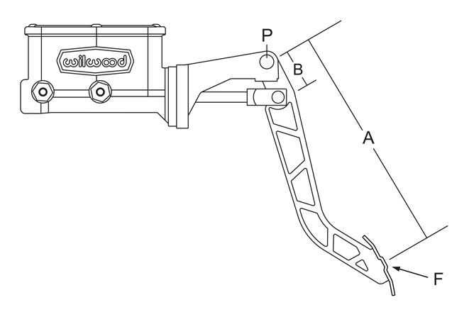
I just measured everything according to Willwood's instructions below. So my pedal ratio is 5.25:1 and travel is currently about 2.5" from rest to accidental poot. There is room for, conservatively, 3.5" more travel.
Measurement A = 10.5"
Measurement B = 2.00"
Pedal Ratio = A divided by B which in this case would be a 5:25 ratio.
So you have the hanging pedals like me. I'm exceedingly happy with 7/8" left foot braking.
For pad compound I'm using Wilwood polymatrix A. The Wilwood rep said they were "too much", but the two other compounds I tried were horrible. Im very happy with the A's
The GTA guys like the PFC 01 or 08 if you want a pad that will last longer. Not cheap though.


