


Driven5 wrote:
In my sho we call that "The Persuation".
Driven5 wrote:
In my sho we call that "The Persuation".

The 'arachnid' hath been defeated!

Its organs hath been harvested as a sacrifice to the car gods.

And its coveted legs shall be bartered in exchange for financing of the Garage Odyssey.


Can you explain to me what the odd little link if on the front inner mounting points? Bottom center of the picture, attached to the a-arm and the inner pivot bolt

And God said, let there be light: And there was light.
Of course, it turns out that God was able to lay down a nice bead without any practice too...Unlike the ape in this picture.
NOHOME wrote: Can you explain to me what the odd little link if on the front inner mounting points? Bottom center of the picture, attached to the a-arm and the inner pivot bolt
I don't know a whole lot about it, but I believe it's called a "toe compensator link"...Which basically compensates for the soft bushings to help prevent excessive toe change during acceleration and deceleration.
Well, nearly 3 months later and I've got 'Chassis #1' almost complete.

It might be a little on the small side as far as cars go, but I'm sure I'll be able to put it to good use. It certainly made for a bit of good practice and there were some lessons learned that can be applied to 'Chassis #2'. Among which, I think my method for attacking those pesky acute angles with the MIG gun will be to weld in an extra wedge of gusset tube after my best attempt to weld into the corner itself...Obviously the 'MIG actuator' needs further calibration as well


Good progress. Keep at it. ![]()

Did you get the Lincoln-specific Torx bolts that join the LCAs to the knuckles? The Thunderbird hex bolts aren't the same and shouldn't be used with the Lincoln arms.
The aluminum Lincoln LCA's, and the associated Lincoln specific Torx bolts, are long gone...Thanks to them my final adjusted price for the Lincoln rear differential, axles, knuckles, calipers, rotors, and sway bar was a whopping $25. ![]()
Guess I wasn't paying very close attention. Somehow I got it in my head you were swapping IN the Lincoln LCAs for the T-Bird iron ones.
Reading is fundamental.
No worries...I can't complain about somebody genuinely trying to be helpful!
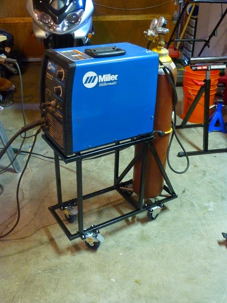
Well, it turns out that ‘Chassis #1’ is actually ‘Welding Cart #1’ too…Coincidence? I think not!


Nice... But needs paint..
Driven5 wrote: Well, it turns out that ‘Chassis #1’ is actually ‘Welding Cart #1’ too…Coincidence? I think not!
I did the exact same thing when I started. It is good practice.

MIGWC01: Officially commissioned for active duty.
Get back to work!
After much agonizing over a myriad of design and manufacturing details, overcoming some personal hardships, and admittedly a bit of procrastination over the past two months…I finally have a flat pack of cut steel tubing lengths for both the outboard and inboard walls of the first side of the cockpit!
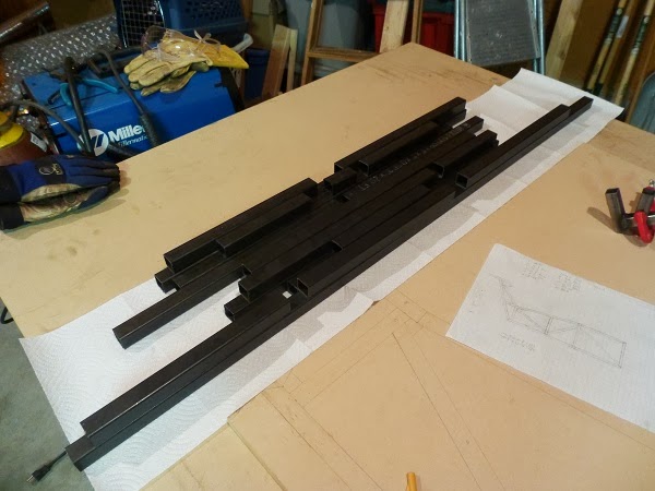
Eating an elephant...One tube at a time.
As is typically the case, the first side took the longest to get the angles and lengths all spot on for fitment.
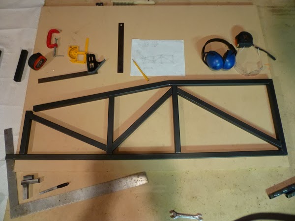
With having gotten the hang of getting the angle right on the steel, and using mostly the same shapes again, cutting the tubes for the second side went much more quickly...Of course, having fewer tubes didn't hurt either.
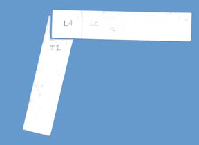
I will be duplicating both of these again for the other half of the cockpit...In other words I'm going to be smart (i.e. lazy) and transfer the patterns over via the magic of Sharpie.
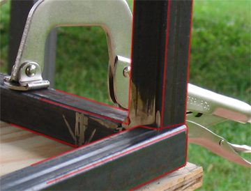
Some people may notice the lack of 'proper' triangulation. This was done intentionally, as I have decided to sacrifice the more ideal loading for two reasons. First is the ability to fully tack all of the tubes in place before final welding any of the seams together. I can't say for certain if this will be useful in helping prevent weld distortion or anything like that, but it's all part of the experiment. The other reason is that it provides better welding access for my MIG nozzle to all seams. Any tube intersection that would have been less than 45 degrees, now has a 0.5" gap and a greater than 90 degree angle. To compensate for any loss in strength or rigidity, there will be 3-sided gussets made from sections of tube with one side sliced off that will be welded into each of these nodes...Which you'll be seeing more of later.
not a bad decision. A nice thick gusset will spread some of the load onto the adjacent tubes.
Good progress. I'll be watching this
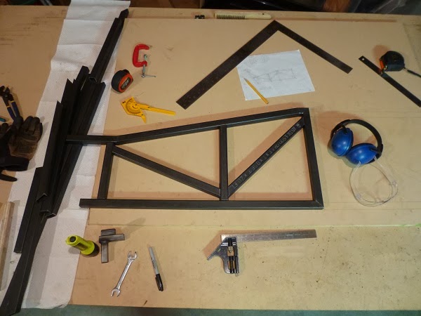
While I'm cutting the second set of inboard and outboard chassis side tubes, I decided that this would be a good time to introduce a surprising 'tool' that has become invaluable to me...

That's right. It's an every day, ordinary, and FREE paint stirring stick from your local hardware store. This one has even been used previously for painting, so as to not be accused of any illicit procurement methods...Although with as much as we spend there, the least they can do would be to contribute a few pristine sticks to the cause. It turns out that while the typical 4x6 horizontal bandsaw has an angle finder to help get it close and reduce the amount of time spent grinding the tube to the exact angle you wanted, it's not terribly accurate. In an effort to reduce rework, I have been using the paint sticks primarily as follows:

First I have carefully measured and planned out my tubes on my work surface, and calculated the necessary cut angles involved. I set the band saw as close as possible to the desired angle and cut the paint stick.
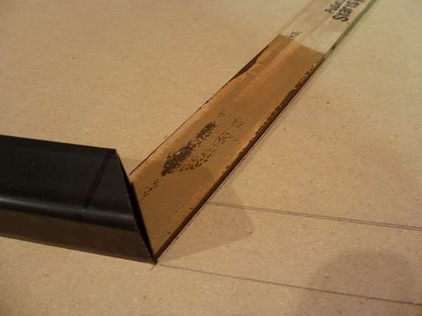
After cutting the paint stick, I can carefully lay it over the plan for the tube end being cut next, and make any adjustments necessary. If there is a mating tube that has already been cut, I will hold their mating surfaces together and see just how close the angle naturally sits to the plan. I only proceed once this looks to be almost perfect.

At this point, if I'm not just copying existing tubes, I should also have markings on the tube to indicate the length of either the long or short side of the angled cut, illustrated by the slightly difficult to see vertical line on the tube in the photo above. Then all you have to do is line the appropriate corner of the paint stick up with the correct edge of the measured line, and then copy the angled edge of the paint stick on to the tube with a Sharpie. With this line in place, and the bandsaw angle set, the tube can be cut. Thu far this method has allowed me to cut nearly every tube to the exact desired length and angle on the first try, with no grinding required.
I'm sure that there are other ways of accomplishing the same end result, and this probably isn't even the easiest, but it has worked for me. It also doesn't work quite as easy once we leave the 2D world and enter the 3D world, but it has already more than paid for itself in saved time, reduced effort, and improved quality.
Driven5 wrote: While I'm cutting the second set of inboard and outboard chassis side tubes, I decided that this would be a good time to introduce a surprising 'tool' that has become invaluable to me... That's right. It's an every day, ordinary, and FREE paint stirring stick from your local hardware store.
That is wonderful. I should have been doing that all along. Thanks for the tip.

Very crafty, I'm stealing this technique! Any similar tricks for round tube?
As they say, necessity is the mother of all invention. Which is exactly how this came about. So being that it's all RHS tubing, I unfortunately have no similar round tube help to provide...But if you happen to have a stroke of genius, let me know.
Paper towel tube. ![]() Make a tight fitting joint with the cardboard tube, the trace onto metal. Thw paint stick should work for round to square tube joints.
Make a tight fitting joint with the cardboard tube, the trace onto metal. Thw paint stick should work for round to square tube joints.
bgkast wrote: Paper towel tube.Make a tight fitting joint with the cardboard tube, the trace onto metal. Thw paint stick should work for round to square tube joints.
I'm really liking the paper dowel idea, too. I was using 1" strips of 3"x5'" note cards to plan the cuts

I'll definitely use the paint stick to test the cuts before using good material
You'll need to log in to post.


