1 ... 4 5 6
NOHOME
NOHOME SuperDork
12/9/14 3:19 p.m.
bgkast wrote: I know you are using an alternative joint design to avoid overlapping welds, but have you considered how you will get the welding torch into some of those tight junctions? Getting good welds in tight spaces has been the hardest part of my build.

Here you go. About 4:30 into the vid they deal with this trick. Not really a trick and not really as easy as they make it look. But how its done.

https://www.youtube.com/watch?v=RSagv69KAB4

Driven5
Driven5 HalfDork
12/9/14 3:31 p.m.

The joint design I'm using is as much about making it easier to get into some of the tight corners, as it is minimizing hidden/overlapped seams. Admittedly there is no avoiding that plenty of them will be a pain to weld. But if all goes according to plan, hopefully still not as much as otherwise. Before this next round of finish welding, I'm also going to try modifying a MIG nozzle or two, to try getting into the tougher joints a little better.

Thanks for posting that video. I too found pulling to be helpful on the acute angles, and a little more heat on the longer stickout, but it took a bit of trial and error to get it figured out. For better or worse, I turn up the gas flow a little bit too.

Driven5
Driven5 HalfDork
2/9/15 5:04 p.m.

Between SWMBO teething, the Plague ravaging our household, more teething, and now more Plague, there has been a precious little time to spend on my dithering in the garage. Let alone updating on my (lack of) progress. However, I do have a few updates to make. So I might as well get started on the longest one, while laying here bed ridden and recovering from my latest brush with death...Also known as the "man cold".

Back before the turn of the year, I once again turned to painters tape in an effort to simplify the measurements and calculations required for cutting a couple of tubes. The difference this time being that these tubes were for multi-axis (3D) angled ends.

As before, lay out the desired tube path with tape. This time, with two pieces of tape forming the opposing sides. I found it to be much more accurate and stable by 'sticking' a small piece of scrap tube between the two pieces of tape near each end to help place the tape. Then wrap tape across the 3rd side to form the 'top' of the cut, as well as mark the two 'sides' for finished length as well. Hopefully this picture will be worth enough additional words to salvage my poor description.

Now the tape can be removed and wrapped over the actual tube being cut.

Trim the excess. Note that the 4th and final edge can be found by drawing a line between the 'bottom' edges on the two sides.

Now be careful how to set this up in the saw. If done wrong, it will cut off needed extra length. If done right it will indicate what needs to be ground off, as pictured below.

Color the excess material in with Sharpie (finally a good use for the Industrial Sharpies) and take it to the bench grinder until the Sharpie is all gone and the tube fits.

I must admit that this method and/or my execution are not as perfect as the 2D tape method. As the tubes move out of plane with each other, the 1" wide face of the tube being intersected becomes less-than 1" relative to the intersecting tube probably plays a part here. I'm sure that I also just need more practice. The end result was that the indicated grind area was a bit on the conservative side, and I actually just needed to grind off a little more metal than the tape line indicated...Which is great, because I really hate trying to grind metal back on to the tube.

Driven5
Driven5 HalfDork
2/16/15 1:15 a.m.

While it might not be obvious to anybody but me, there have been two other shining points of progress over the last two months. First was the construction of the 4 rear bulkhead supports. These will serve dual functions of strengthening the rear bulkhead, as well as being the lateral seating supports. They're not actually tacked on in this picture, just mocked up. Second is the lateral tube and diagonal just aft of the shifter on the transmission, which are tacked in place now.

It should come as no surprise that there is unlikely to be any physical progress over the next week or two, however it's not for the usual reasons...I am actually in the process of sorting out the rear suspension geometry so that I can finish planning the rear bulkhead bracing.

BeardedJag
BeardedJag Reader
2/16/15 8:47 a.m.

Just started following! This is great. Keep it up!

Driven5
Driven5 HalfDork
2/17/15 11:26 a.m.

Thanks. Welcome aboard the crazy train.

Driven5
Driven5 Dork
5/10/15 7:07 p.m.

My new lawn ornaments.

Dusterbd13
Dusterbd13 SuperDork
5/10/15 9:19 p.m.

What body is that?

And im following along. A locost is on my list for when im not burned out on building cars anymore. Right now im just watching and learning.

Driven5
Driven5 Dork
5/10/15 11:54 p.m.

That's one of the "Lalo" (lay-low) development bodies from Jack McCornack at Kinetic Vehicles...Well, not the whole body obviously, but the most important panels. It's based on Lola Mk1 bodywork, modified to fit Locost chassis proportions, and roughly cuts the coefficient of drag in half. Among other endeavors, Jack is probably the premier supplier of fiberglass bits for Locost builders in the US.

Driven5
Driven5 Dork
2/18/16 1:11 a.m.

Evil, thy name is rust!

Well, nearly a year has passed with no physical progress on the car. Plenty of investigating new ideas, designing, and planning have occurred, but nothing tangible. However, I got the perfect Valentine’s Day gift from SWEETA this year. Garage time! Not just after everybody had already gone to sleep, like I normally relegate myself to, but during the day as needed to take on scourge of steel…Rust.

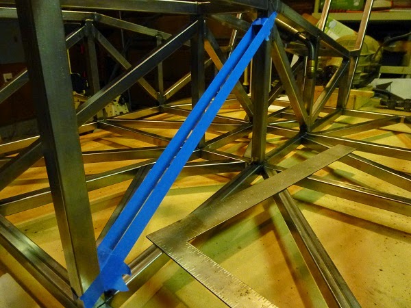
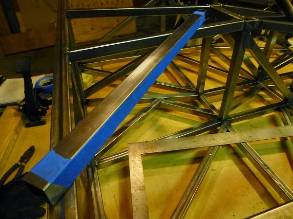
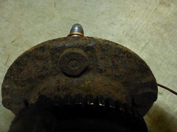
The previous weekend, I had actually started modifying the spindles to accept a standard aftermarket lower ball joint. This needed to happen before I could take measurements that would allow me to design a front suspension geometry that will match my preliminary rear geometry. The problem being that I also was uncertain that these particular spindles would be worth continuing my efforts with, as they were originally purchased back when we lived in the rust belt, and looked every bit of it.

I looked into potential alternative spindle options, but decided to first see just how well these ones might clean up. A little research into de-rusting methods led me to decide on electrolysis. I mean, if it works on unwanted hair…So why not unwanted rust, right?

So here the setup for my little ‘science fair experiment’ that I ran over the weekend.

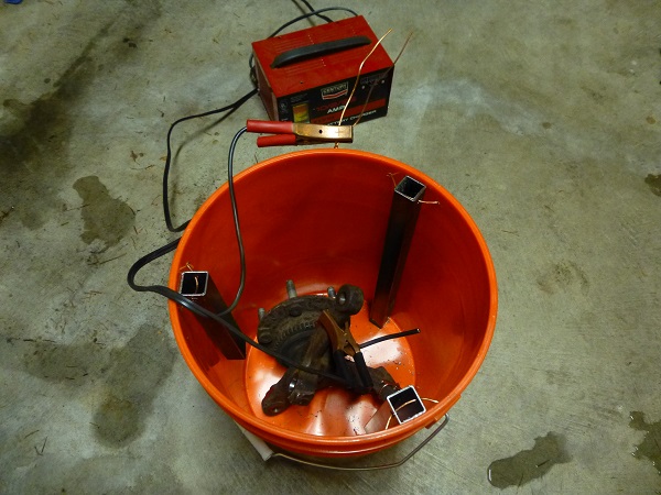
There is an array of three pieces of scrap mild steel^ that act as the anode, being sacrificed to the car gods. Well, I hope they were scrap. But it’s been a long time, so I’m not totally positive. Then again, if they weren’t scrap before, they certainly are now.

The part being de-rusted acts as the cathode, and the battery charger supplies the necessary electrical current. The bucket is then filled with an electrolyte solution^^ typically made from 1 tbsp washing soda or baking soda per gallon of water. Apparently you can also convert baking soda into washing soda by baking it…Which begs the question of whether that means you can also convert washing soda into baking soda by washing it? Anyways, after adding 4 gallons of the electrolyte mixture to the 5 gallon bucket, I was ready to go. Almost immediately after plugging in the battery charger, set at 12V/10A, it started to work. There was a ‘fizzing’ of hydrogen^ and oxygen being released, and while rust particles began to invade the solution.

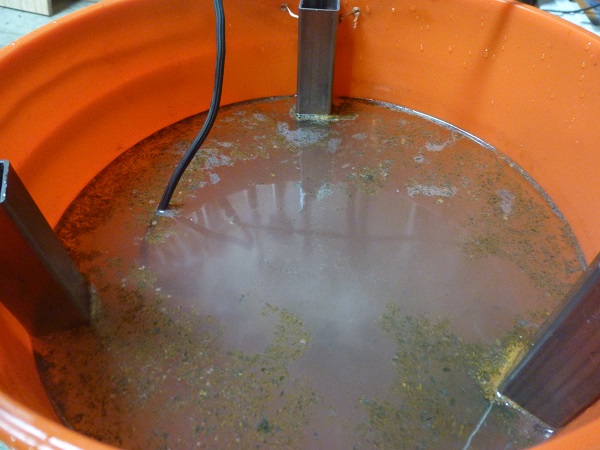
After a while, the water began to look much less inviting.

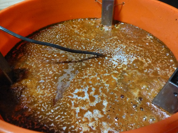
And whenever the amperage would drop into the 2A-4A range, I knew the anodes could use a cleaning.

At this point, I would skim the surface of the water to remove the sludge buildup on the surface…After unplugging the battery charger of course. I would then remove the part from the water (rubber gloves are helpful here), transfer almost all of the solution to a second bucket, dump the little bit of heavier sludge**** that had settled on the bottom, clean the anodes, put it all back together, and top off the water. Remember that while the release of hydrogen and oxygen may lower the water level, the no sodium carbonate is released from the solution. So the only need to add sodium carbonate that needs to be added is to account for any solution lost during de-sludging.

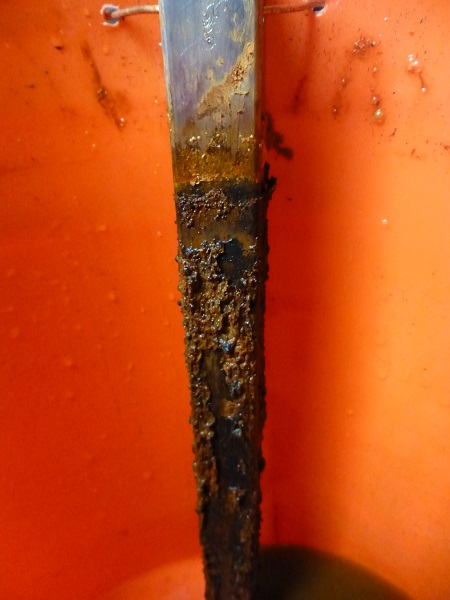
As time passed, obviously the amount of rust particulate in the solution increased. However, I also noticed a corresponding increase in the frequency of needing to clean the anodes, and the aggressiveness with which I had to do so to get good amperage when I resumed the process. Early anode cleaning was sufficient with a wire brush, but as the electrolyte became more contaminated I would then hit it with a flap disc on an angle grinder too. Of particular interest was that the spindle didn't appear to be changing anymore, about 12 hours in or so, but I was still getting the floating red sludge. So I decided to totally change out the electrolyte solution, and hit the anodes with an abrasive disc again. Voila! There was nothing but pure electrolysis for the next few hours, with virtually no new rust particulate in the water, rust formation on the anodes, or loss of amperage. My experiment was complete.

So, how did the parts actually turn out? You’ll just have to wait until the next installment to find out…And I promise it won’t take another year!

.

.

^If you would rather not get or give cancer, don’t use stainless steel as your anode. While this requires less cleaning than mild steel, it releases toxic hexavalent chromium into the solution.

^^If you would rather not wage chemical warfare on yourself, much like my previous entry on Phosgene, don’t use table salt (sodium chloride) for your electrolyte. While this will create an electrically conductive solution, it releases toxic chlorine gas. Which can additionally combine with the released hydrogen to create hydrochloric acid.

^^^If you would rather not have your workspace go the way of the Hindenburg, keep your setup in a well ventilated area and keep it away from sparks or flames. This includes pilots for gas water heaters. It is also one of the main reasons for unplugging the battery charger every time before moving anything around on the setup.

^^^^If you’ve followed the preceding precautions, the mixture ‘should’ be non-toxic and environmentally benign.

NOHOME
NOHOME PowerDork
2/18/16 5:34 a.m.

The hot set-up for this game is carbon or graphite gouging rods available from your welding supply vendor.

I have not used the graphite rods, but I have been down your exact path so I have a pretty good idea what your results will be.

DeadSkunk
DeadSkunk UltraDork
2/18/16 7:28 a.m.

I renewed the suspension components on my Miata using this method. It worked surprisingly well.Because of the size of some components I had to use a large garbage can instead of a bucket. There's a YouTube video out there showing a guy derusting his trailer frame. He built a tank from wood and a plastic tarp and used a welder as the power source.

Driven5
Driven5 Dork
2/18/16 11:46 p.m.

In reply to NOHOME:

I'll probably touch on this again in my next entry, but yeah, apparently carbon/graphite makes for a nicer product coming out of the vat...And if I was dealing with a larger quantity of rusty parts, I would have been willing to put more effort/money into procuring some. But I was on a self-imposed deadline, and just wanted to get on with finding out how well the process would work on my potentially junk spindles. I'll still probably look around a little more for some before next time I give it a try. However, it's hard to beat the price and availability of mild steel, even if it is a bit messier. The carbon/graphite rods/bars I was finding would have driven the costs up towards Evapo-Rust territory.

Driven5
Driven5 Dork
2/21/16 12:45 a.m.

So now on to the results of my electrolytic rust removal ‘science fair’ experiment. You’ll notice that I used some extra solid copper wire to ground the hub rotating assembly to the spindle. This was to ensure a good electrical connection between the two, ensuring the treatment would act on both. Don’t worry about any potential side effects on the longevity of the bearing, as I planned to replace them all along anyways. This just allows me to use what I’ve already got for measurements and mock-ups.

Picking up where the experiment left off last last time, is the spindle immediately after the electrolysis treatment had completed:

Quite a difference! Now that pretty black coating electroplated on it is actually not desirable, and needs to be removed. Also note that some areas, like the rotor/wheel register don’t have it. That’s because this process only acts on the rusted surfaces, and any rust that was in those areas was little more than superficial surface rust. I chose to let the spindle soak in a mild acid solution (Distilled Vinegar) for an hour or so to soften the black coating, This was followed by a good thorough scrubbing with a small wire brush, revealing the bare metal underneath:

Now we’re getting somewhere! This is actually after a quick dip in water to neutralize any remaining acidity on the surface. Also note that I was able to get the wheel speed sensor off, which thankfully when the bolt is no longer rusted in place, a conventional 6 point ¼" socket will fit firmly enough over the external Torx head fastener to remove it. However, at this point, my freshly bared and unprotected metal was rusting right before my eyes as the part dried. I had heard it would rust within the hour, but we’re talking by the second. So I decided to speed up the process by using a hair dryer to get the water out of all the nooks and crannies. It was both intriguing and concerning to watch the rate of 'flash rusting’ multiply with the forced air drying. This is where the Scotch Brite pads came in handy:

Holy crap nuggets! I never thought the spindle would ever look this good again. The flash rust was totally eliminated, leaving the surface of the part at least stable enough to take a few minutes and spray a coat or two of high temp primer on it:

So there you have it…A cheap, but admittedly more involved than anticipated, method for taking ugly rusted parts and making them look nearly as good as new without any fancy equipment.

Now, apparently pure carbon/graphite rods for the anodes will not produce the floating rust-sludge, eliminate the need to regularly clean the anodes, and doesn’t require as much cleaning of the finished part either. In other words, the whole process would be significantly cleaner and easier. If I was de-rusting parts on a regular basis, or doing so with a large quantity of parts, this would absolutely make sense. However, it’s considerably more expensive, and much less readily available locally, than mild steel. If I can find a few rods for cheap enough, I would certainly consider this for the other spindle, but I won’t be holding my breath for that to happen.

NOHOME
NOHOME PowerDork
2/21/16 6:06 a.m.

Did you actually get a price on the graphite rods? As a welding consumable I cant see them being that expensive.

Driven5
Driven5 Dork
2/21/16 11:36 a.m.

Unfortunately the local welding shop I called does not carry the plain uncoated gouging rods, at least not in stock, only the copper plated ones. And even if they did, they only sell them in full boxes of 50 rods.

codrus
codrus GRM+ Memberand Dork
2/24/16 12:49 a.m.

So what is the black stuff that got electroplated on?

NOHOME
NOHOME PowerDork
2/24/16 5:31 a.m.
codrus wrote: So what is the black stuff that got electroplated on?

2) What is the Black Coating?

The cathodic precipitation of insoluble black substance onto iron artifacts that are being electrolytically de-rusted is the major problem encountered with sodium carbonate electrolytes. This black coating is a Sodium Carbonate compound precipitating directly from electrolyte.

This precipitation is more likely to occur at high electric currents, and when tap water containing high levels of carbonate is used to prepare the electrolyte (another good reason for using de-ionized water in the electrolyte!). Black carbonate precipitation is very rare in sodium hydroxide electrolytes.

So if the tap water is used to prepare the electrolyte, the de-rusted artifact will sure be coated with the black carbonate that strongly adheres to the de-rusted surface. It is also hard to wash this black substance off fingers if they get stained with it, so make sure you wear the rubber gloves

http://www.metaldetectingworld.com/remove_black_coating_p27.shtml

1 ... 4 5 6

You'll need to log in to post.

Our Preferred Partners
UfclaiF32mGKus2lvKNSwLWZxTX4XTX5GlD7Mk18eBsB4Vc3b4YSEdYuXP0WCQ6K