1 2
awalker
awalker None
11/30/18 4:29 p.m.

Lets start off with an introduction. My name is Alex owner of AW autoworks https://www.facebook.com/AWcustomAutoworks/ which is just a small individual owned custom body and paint shop. I work in partnership with SCHWA Motorsports who specializes in tuning and custom engine swaps.


So let me introduce you to the First car. This was originally an 88 Fiero CJB Coupe converted to a GT with a 3800 SC. Chris was unfortunately in an accident with a Semi, he originally thought the car was a goner and began to part ways with the car. Once I looked it over I decided that the car was salvageable with a good amount of work. After long discussions with Chris we decided to build an OEM+ designed car. Taking bits and pieces of other cars we like, adjusting the design a little and combining all of them to create a masterpiece. The following are our ventures in this build I hope you enjoy


Here are pictures of the accident. This happened back about 4 years ago. After the accident the owner decided to part ways with it and he started to part the car out. The 3800SC set up went into a Mera for one of his customer and the rest of the car parts went into other various cars. He then ended up giving me the bare frame. No suspension, cooling, engine, trans, or any body panels for that matter. I did have an 87 coupe that ended up being so rusted that it became my donor car for body parts and some odds and ends. Picked up the cooling tubes and such from the local junk yard and pieced it together just to get it roll able.


awalker
awalker New Reader
11/30/18 4:32 p.m.

So apparently after digging through my phots I couldn't find any starting photos of what I started with. I did some digging around from the local junk yards and fellow club members and took a big chunk out of my own parts stash to get it to a rollable chassis as shown below.


I have to get the body on first so I can know just exactly what I'm working with as far as frame damage. doors and quarter parts are in the process.

After the initial frame pull this is where I am. Its not too far off but still quite a ways off. now that I have the doors on I can start to fine tune the adjustments. Now keep in mind most of the parts on this car probably wont be used mainly just using them for mocking up purposes. I did swap the wheels and tires over from another Fiero I own which turned into a parts car because of the rusty frame. 


awalker
awalker New Reader
11/30/18 4:34 p.m.

I have done my final Frame pull and ready so cut out the old and bring in the new. I sectioned out a B post from a donor car for replacement, A plasma torch does wonders to the donor car. (muahahahah Fire). So time to start grinding and cutting on this frame. and get the crunched up outer off the car. Once the outer was off I was able to make final tweeks to were the post needed to be. The door fits and lines up perfect with the outer skins. Being a body guy I have a stash of visegrips as you can see. This allows for precision cuts and fitment. Once I get it fit into the perfect spot I take some sheet metal screws and screw it into place that way I can take it back off. Prep all the metal for welds and come back to the exact same spot. Once prepped I put the panel back on and started welding away. I lapped the upper section and had to sleve the lower rocker for a butt weld. Welded all my spot welds up and brushed some seam sealer over my welds to bring that factory look back.
I prepped the post and sprayed in some por15 to etch into my bare metal and give it that flat factory frame paint look. Those pictures are to come. I forgot to grab some pictures last night. 


I do just want to brag a little about how these welds just sank right in Minimal grinding needed 

awalker
awalker New Reader
12/3/18 10:30 a.m.

 lets get to what you all want to see/know about the engine. I am going to be running a gen2 60v6 aluminum head 2.8 with pivot ball rockers and a flat tappet cam. But I will be upgrading the intake manifold to the late gen3 3400 parts for a hopefully nice increase in upper rpm flow. Along with this I am going to be installing a Designs 1 turbo kit. When i got this motor the fiero exhaust manifolds had already been adapted to the heads as the engine had been previously installed in a Fiero. So with the turbo kit on the shelf and having a love for boosted cars I decided it was a good time to put the parts to good use 

So here is the 2.8 engine with the aluminum heads and the 3400 intake test fitted with the gen 2 valve covers still in place:


Now one thing that needs taken care of when swapping intake is the fact that the gen2 intake actually has the oil fill cast into it. Simple enough all the aluminum head motor valve covers fit on the different generations even to the fact that I swapped on valve covers off a gen4 3900.

Since we are now working with a 2.8 with 3400 intake and I will be controlling all of this with a Microsquirt stand alone computer, which sadly can’t handle SFI, nor does the engine have the cam sensor needed for SFI, I decided to remove the casting marks. I also removed the EGR valve, extra vacuum fittings and a couple mounting bosses that were no longer needed:


Vacuum fitting removed:


EGR flanges removed:


Mounting bosses and such removed:


Now that I knew it all fit it was a matter of seeing if gaskets lined up. While they do line up, i wouldn’t say they line up well enough to recommend this, and honestly it might all crash and burn due to this  The ports on the gen 2 head are a little lower into the valley than the gen 3 intake, its fairly close, but could be better. Since this is a quick build to get the car on the road, and I didn’t want to swap to the 3400 heads I had on the shelf I added a little silicon and we will see the results before too long:


You can also see in the last picture that the ends of the stamped rockers need clearance for the larger intake manifold.

For belt routing, using the gen2 AC compressor set up and timing cover, I Low mounted a fiero alternator and made a bracket to hold a gen4 3900 belt tensioner. Added a lower smooth idled and tapped a hold from the power steering mount for a upper ribbed idled and ended up with this, simple but pretty good belt wrap on the important parts:


Since I am going to be running a stand alone ECU I am able to run what every ignition set up I want, and even can waste spark fire LS1 based ignition coils. So modifying some left over brackets from my turbo vr6 vw rabbit I made some coil mounts and used the ls1 coils and plug wires:


Also you can see some color going onto the engine, well black:


I repainted the intake manifold adding a decal stencil for some fun and hopefully today I will be test fitting the motor, need to clean/paint some more parts and swap the oil pan over that has the turbo drain welded into it.

awalker
awalker New Reader
12/3/18 10:32 a.m.

 as far as the wide body goes our goal is OEM plus. Keep it as stock looking as possible but improve upon the design a little. We were aiming for 2 inches wider on each side but ended up just a little shy of that. To start out with I had to build most of this on the car so I could keep my gaps and body lines with the doors, bumpers and quarters. I started with 2 stock fastback clips. One was junk and all cracked out so no sad faces when you see how the process works. So to start I separated the outer skin of the junk clip with the inner structure, This gave me a skin that was flexible and able to overlay the existing quarter. After some trimming up I was able to get the fitment that I wanted. Now the task was to attach the new panel to the stock quarter. With my experience in the body shop I know of some good products for this operation. 3m makes an SMC panel bond 8219. I got all of my panel prepped and ready to make the step to attach the panels together. With a bunch of clamps and sheet metal screw (temporary) here is was I ended up with


Once the Panel bond was 100% dry now I could come back and start the glass and body work. I had to grind back down where the panels met and grooving out a little bit of material in order to get proper adhesion with the thin layer of fiberglass. (SMC resin not traditional). once the glass was dry I went back over with standard body filler to do my final coats. Every step I get closer the more excited I get to see the end result. here are some photos of the body work


I had to get some comparison photos just so see the difference just a little bit better.


awalker
awalker New Reader
12/3/18 10:33 a.m.

The next step is to attach the mounts for the bumper, quarter and fuel door. Back to the same product I used before. I prepped the inside of the panels and used the mounting points trimmed off of the inner structure.


awalker
awalker New Reader
1/16/19 9:35 a.m.

Next on our list of things to tackle is the rear lip spoiler.
the goal with this is to keep this small and follow the oem lines with the tail lamps and with the decklid
I found a few photos of what I'm aiming for

I will keep you updated with the progress start to finish


awalker
awalker New Reader
1/16/19 9:36 a.m.

've been able to make a little more progress this week on the rear lip spoiler. Getting the profile just right and the engineering to make it durable. My worry was making a wing that would crack out after constant use of pulling the deck lid down by the lip every time it was closed. So I decided to go with a rib style wing where there is a support ever 2 inches. The key to this was to make all the supports the exact same, and they had to fit the deck lid just right. every support got fiber glassed into place then I but a light layer of balsa to skin the supports. the internal cavities were filled with pillar foam for extra support but to keep it light. Now that the structure is built and shaped its time for a few layers of fiberglass. 


I will be getting a few more photos of this process later on in the week

awalker
awalker New Reader
1/16/19 2:34 p.m.

 was able to get down to the shop this Sunday. I was able to get most of the body work completed on the main part of the spoiler. This was completely built out of scratch. It has a very common structure to an airplane wing, individual ribs keep the rigidity, It was filled with a cavity foam for support, Layered over with a balsa, fiber glassed over the balsa and into the deck lid its self with a final coat of body filler to make it straight. I still have to create the spoiler caps that are molded into the upper quarter but that is going to have to wait until I get the car so I can assure perfect alignment. 


Being at a stopping point with the spoiler I decided to move ahead to the extractor hood. I went out to my car to get proper measurements where the radiator ends and able to start the actual scoop itself. If I remember right it was something like 11.5 inches from the center point on the hood to the back of the radiator fan. I had to keep the scoop small enough to fit between the main supports of the hood where the hinges bolt up. it is as wide as it can go without major modification. The front edge of the scoop is parallel with the front edge of the hood and not just straight across, Its just a minor detail but really adds to the profile. I found and old wing stand and cut it up for the center support, Using that saved a lot of time and again adds a uniqueness to the scoop. I started to make the uprights to the sides of the scoops, the first attempt I went straight up and down. It didn't look right at all, it looked to homemade. so just adding a bit of angle allowed me to create more of a flowing look to the scoop. Here is a tip that helped me keep that upright placed when I glass it in. What I did was take my cut off wheel and create a notch for the upright to sit in so it would stay in place and not slide about. When clamped it puts the pressure into the notch as opposed to just folding the upright.


awalker
awalker New Reader
1/16/19 2:35 p.m.

everything has been bonded and a bit of sanding done. I had to do just a little more glassing but all is good. I did flip it up to show where the cut was made to allow the skin to flex downwards. There is a factory notch in all the bracing and that's where I stopped the cut and finished notching out all the way to the outside skin to allow the flex. I will be building the sides up and glassing the inside as well but that's to come shortly


awalker
awalker New Reader
1/16/19 2:39 p.m.

was able to finish up the outside body work for the outside and get it into primer. This is really the first opportunity to really see all the angles and curves. It has turned out better than expected. I will start the fiberglass work on the inside next.


was able to do a test fit on my car to check clearances. There will have to be about a one inch notch out of the frunk but other than that everything clears quite nice.


Doc Brown
Doc Brown Dork
1/16/19 5:34 p.m.

Moor pictures!  this build is awesome! 

pimpm3
pimpm3 SuperDork
1/16/19 7:17 p.m.

Good job!

awalker
awalker New Reader
1/17/19 10:07 a.m.

This is the engine bay before brackets and battery tray were removed, and I got the bay painted and insulated:


Now for the in-depth crazy part that hopefully will help somebody down the road 

In my shop I specialize in Megasquirt and Microsquirt stand alone computer installs, anything from a VW VR6 with 6 throttle bodies, coil near plug ignition, and a turbo to a VW W8 with twin turbos, I have also installed Microsquirt on a 3900 in a fiero with fully functioning variable cam shaft.

What I haven't done is run a Microsquirt off the GM 7x crank trigger wheel found in the 60v6(until the last few models with a 60-2 wheel) and in some Ecotec 4 cylinders. Well fast forward to the engine wired and 6 LS1 ignition coils installed. White setting ignition timing I found that the coils were firing roughly 120 degrees advanced. With some crank trigger wheel options in the MS world you can adjust the crank trigger angle offset to whatever you want. Sadly the GM 7x wheel only allows 20 degrees advanced or retarded, just not quite enough  So I had to get creative, since v6 even fire engines fire every 120 degrees I got an idea that if I reordered the coils to effectively give a 561234 firing ordered as compared to the crank angle that I could get this 120 degree offset lined up. So before I did any wiring I grabbed the cylinder 5 plug wire and shot the timing light while cranking and it was spot on! so with a quick rewire of the coil trigger pins on both sets of coils and the car fired right up!!

awalker
awalker New Reader
1/17/19 10:14 a.m.

In reply to Doc Brown :

Thanks.    Its a Very Fun build because it is improving the design of the vehicle.     We have so much more on our list other than this car.   We are also currently planning on moving to a larger newer shop in the very near future.   We are suppose to break ground this spring.


Stampie
Stampie GRM+ Memberand PowerDork
1/17/19 10:25 a.m.

I love the body mods. OEM + is a great term. Very tasteful yet different. 

awalker
awalker New Reader
1/17/19 11:17 a.m.

I am able to hang the panels for proper fit to check gaps and finish body work. I was able to mount the quarter panel's rear bumper and lamps. once complete I will be able to do the finish body work before paint.


The car still needs lowered down an inch and the wheel and tires are just for mock up purposes.
I will be finishing up the spoiler to build it into the quarter and curve it down once I finish aligning the body. Its a slow process but it always pays off in the end

awalker
awalker New Reader
1/17/19 11:19 a.m.

The next step is to widen the fenders, my goal is to widen them at least an inch and a half. Here is the profile I started with. 


My next step was to cut out the "flare" out of an existing fender. I had to cut around all of the perimeter and cut the back at the molding line to allow for the proper flex of the plastic.
I lined up the wheel well and inserted temporary spacers, heated up the outside flare and set it over the top of the old fender. I have what I call Klincos or temporary rivets to hold it into place


I did have to trim the front bumper mount and re-attached it in a slightly different position
as far as the lower I ended up cutting out a fender scoop just to make it easier to arch to the shape I needed.


Once I was able to ensure proper fitment It was time to remove the flare, prep for bonding and feather out the edges for smoother transition for body work.
I prepped with a 50 grit rolac disc down to bare plastic to ensure a good bond between the two materials. I used a 2 part 3m epoxy 8223. It is a flexible panel bond and used a plastic prep before the panel bond was applied. Once bonded I placed my temporary rivets back into pace to keep pressure on the bonded area. Once dry overnight I was able to remove my rivets and my temporary spacers. I finished of the outer body work and filled the cavity with a pillar foam to keep vibration down. 


We will be making fine tune adjustments with the wheels and tires and suspension to fit just a little bit better.
now on to the rocker moldings and the passenger side fender.

Stay tuned for more.

awalker
awalker New Reader
1/17/19 4:14 p.m.

 same process as above with the driver side


I also made some good progress back on the Driver side with fitment of the rocker panel. I had to make 4 different cuts to allow for the bend needed to follow the flaring of the fender and quarter panel. I still need to do fine tune things on the front side. Once they are fitting good I will hot staple the rockers and then I will finish them out to fix the cuts made.


I will update with a step by step on the rockers once complete

awalker
awalker New Reader
1/17/19 4:16 p.m.

SPOILER ALERT!!!!
I have almost finished up with the spoiler tips.
Its been a bit of a process. in the building of the tips, trying to get a good looking arch that goes with the body of the car and arch of the taillamp pocket.


I do have some finish work to do before primer but that's on step closer to completion

awalker
awalker New Reader
1/18/19 8:19 a.m.

PRIMER!!!!!!!!!!!!!!!!!!!!!!!!!!


awalker
awalker New Reader
1/18/19 8:19 a.m.

everything has been primed and assembly is almost complete. I have to adjust some gaps and finish moldings and mirrors. I am letting it sit in primer for a few weeks or so to allow all the body work to finish shrinking if there is any. The car will be put back on a trailer and headed to SCHWA Motorsports for the correct wheels and suspension, and tuning. 
Everything is looking better than expected. There are some pin holes and such that will be addressed before paint.


awalker
awalker New Reader
1/18/19 8:27 a.m.

here are some more angles


I still have some panel gaps to fine tune, but this is just a mock up to make any final adjustments before paint work


awalker
awalker New Reader
1/22/19 3:39 p.m.

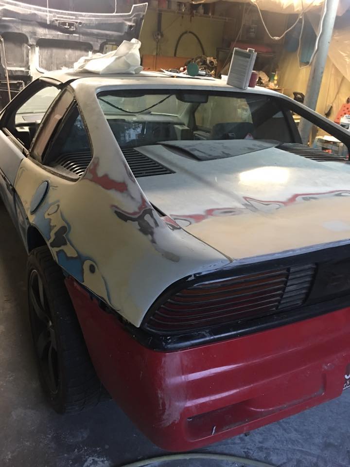
I have had some hurtles on the car that I have been working, first and for most I have been having the joy of red hot exhaust manifolds and fireballs coming out the exhaust way larger than needed or wanted.

Please skip this paragraph if the stand alone computer stuff gets a little monotonous and time consuming this might get boring. So to start off when it comes to Microsquirt stand alone you end up needing to input a crank, and often cam, position input into the ecu to determine spark and fuel timing. Well ideally the stand alone computers use a Hall effect sensor, you provide it power and ground and it pulses the given power to the computer as a consistent input voltage. Most cars these days use a Variable Reluctance sensor, often called a VR sensor, and it uses the crank trigger wheel to produce a voltage in the sensor with the use of magnets, the problem with these sensors is the higher the rpm the higher the voltage tends to be. On a stock ECU matched to the car this isn't a problem at all, but on the stand alone often times the voltage gets too high and the signal gets lost. Now one last thing to keep in perspective is the VR sensors are just two wires, doesn't always tell which is positive and which is negative and can often be run either direction with the change of some settings. Well given all that background I ended up with a setting off and the wires flipped and once that was sorted I was loosing tach signal at higher rpms, due to the high voltage. So after adding a resistor inline, which burns off some of the voltage from the sensor, I was back in business with a motor revving to 6k+ and much less cutting out.

You can skip this paragraph too, but it isn't as stand alone heavy, and more just engine technical heavy  The next challenge I was having was the glowing red manifolds, as the fiero community is well aware of red hot manifolds is simple put due to high exhaust gas temperatures. For the stock 2.8 this is most commonly found from cracked manifolds sucking in air and making a lean mix in the manifold and there for hot exhaust. Intake manifold leaks can cause this two, but I was able to rule both of them out with some checking, so I had to dig farther. One thing is isn't often mentioned with the Designs One turbo kit, is the that the turbo is too small, you hear it when people talk about putting it on the 3.4, but truthfully its too small for the 2.8 too, especially if anything has been done to the motor, like high flowing aluminum heads and intake  So we get back to when I was getting red hot manifolds, after about 5min on the highway at 70mph my manifolds were glowing and glowing quite brightly, including the whole turbine housing and the beginning of the downpipe. Well long story a bit shorter, one thing you always need to do on a stand alone car and I hadn't done since the car was running was confirm ignition timing, well I was retarded by 3.5 degrees, its a simple process of setting the engine to run at a static 10 degrees of ignition timing and checking to see how far off you were, I was running 6.5 degrees, so was off the whole time. So add that to the fact that the turbo is so small that 70mph I was spooling the turbo to almost 0 vacuum just cruising, well this caused the engine to go into the the timing of 12 degrees for under boost and richening up, well compound that with 3.5 degrees off your down to 8.5 degrees of spark timing, very low for this motor, and in turn red hot manifolds. After fixing these issues I had it running pretty nicely, but sadly not before I had taken a drastic step and changed the turbo to a larger one I found locally.

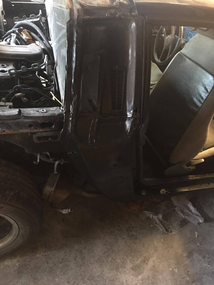
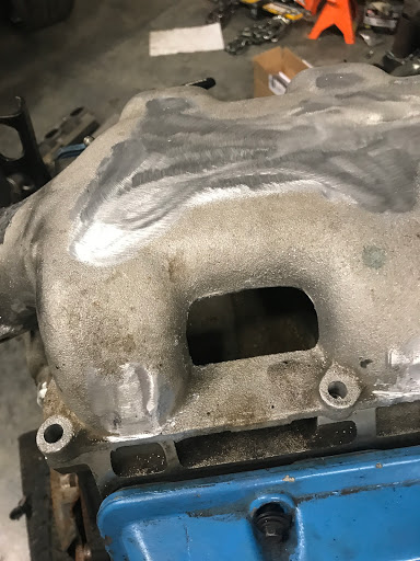
Now for the turbo conversion build, we will start with a few things, and most of them are related to my specific install, but hopefully it can be useful information for somebody else considering a 3x00 swap. First is the cast manifolds that match the motor are much larger sized than the fiero manifolds port wise, and the 2.8 or gen 2 manifolds both will not fit the gen 3 heads, the port on them is bigger than the manifold itself. So I went ahead on my build and converted the car from the fiero manifolds and cross over to the 2.8 gen2 aluminum head manifolds and cross over, eliminating the down pipe flange and egr port hole. Now for the new turbo, I got a JDM subaru legacy turbo, its a twin scroll turbo for a 150hp 2.0l 4 cylinder, so a little small still, but the same brand as my turbo that was on the car so lots swap over, but I did have to build a new crossover pipe and downpipe, and change my charge piping a bit.

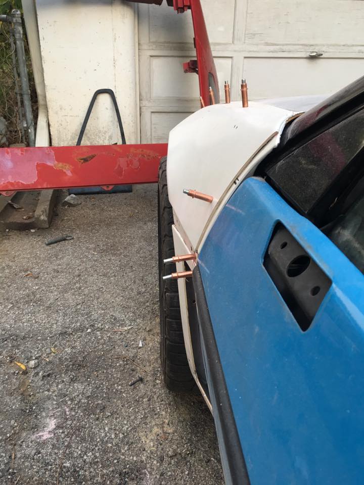
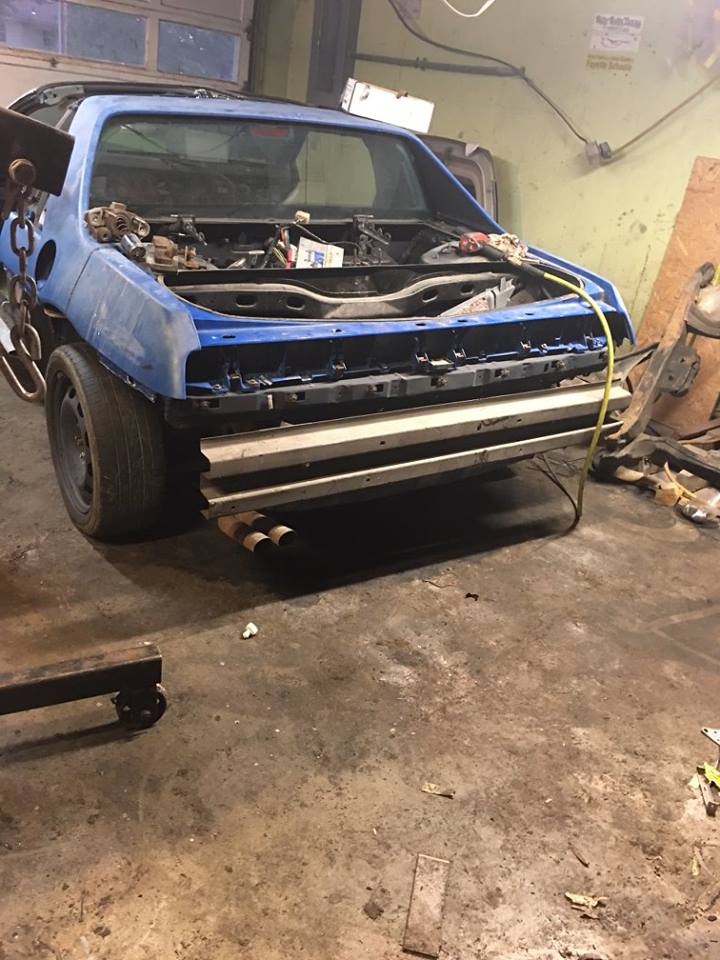
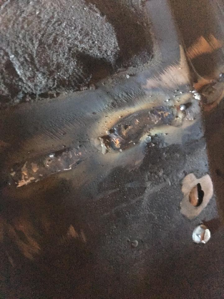
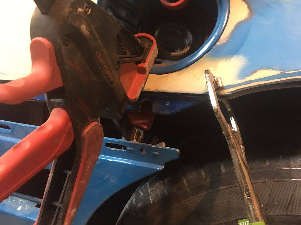
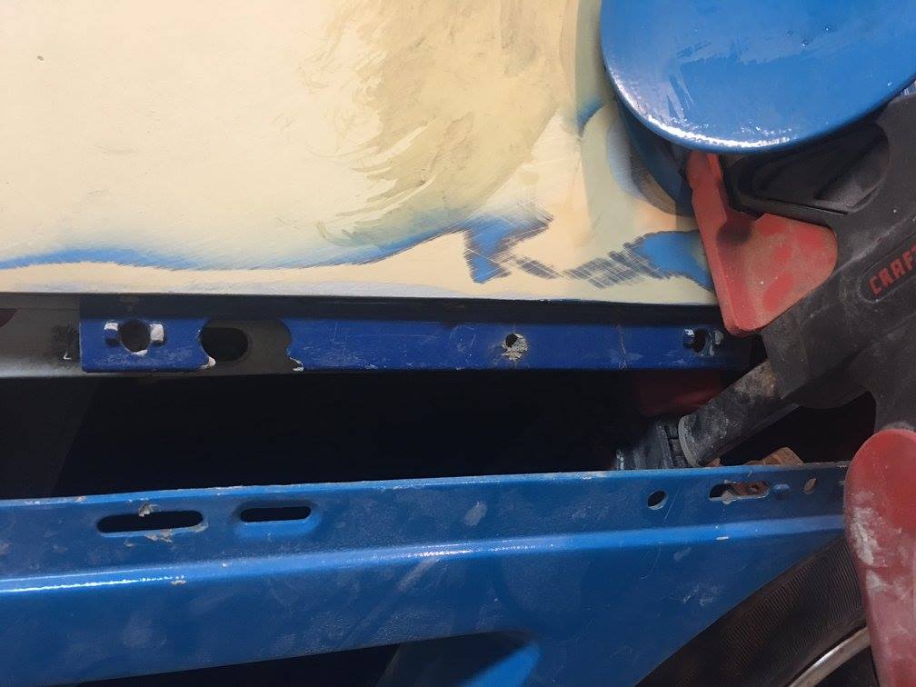
Here is the crossover mock up with the turbo flange:


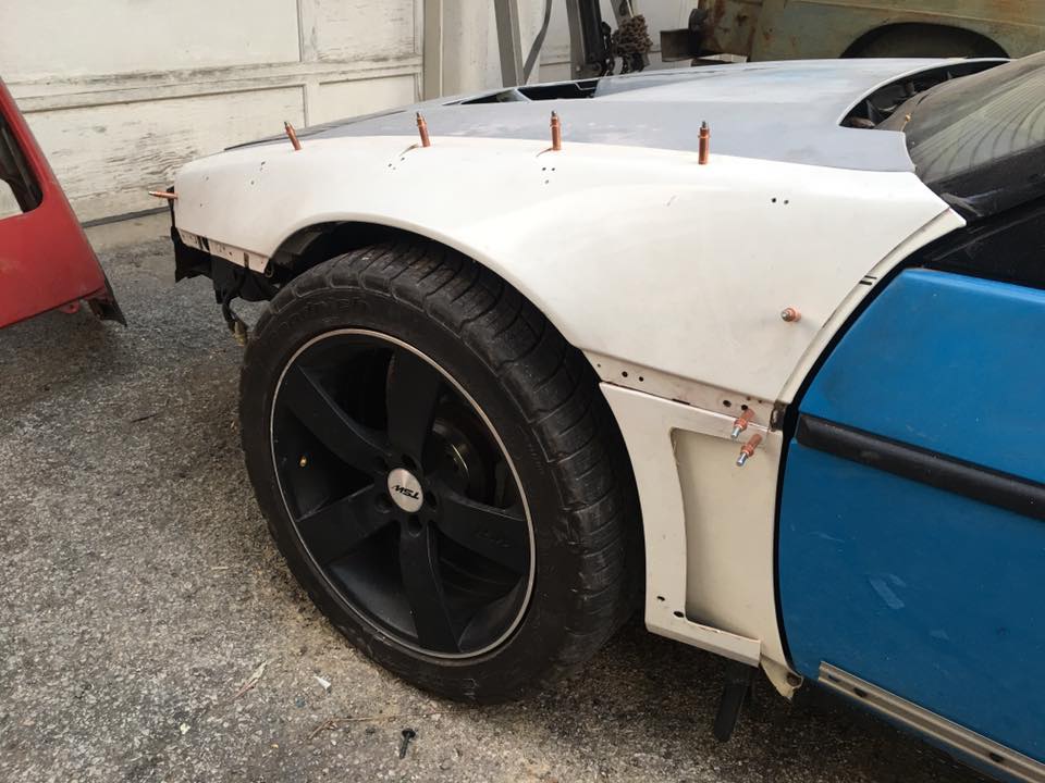
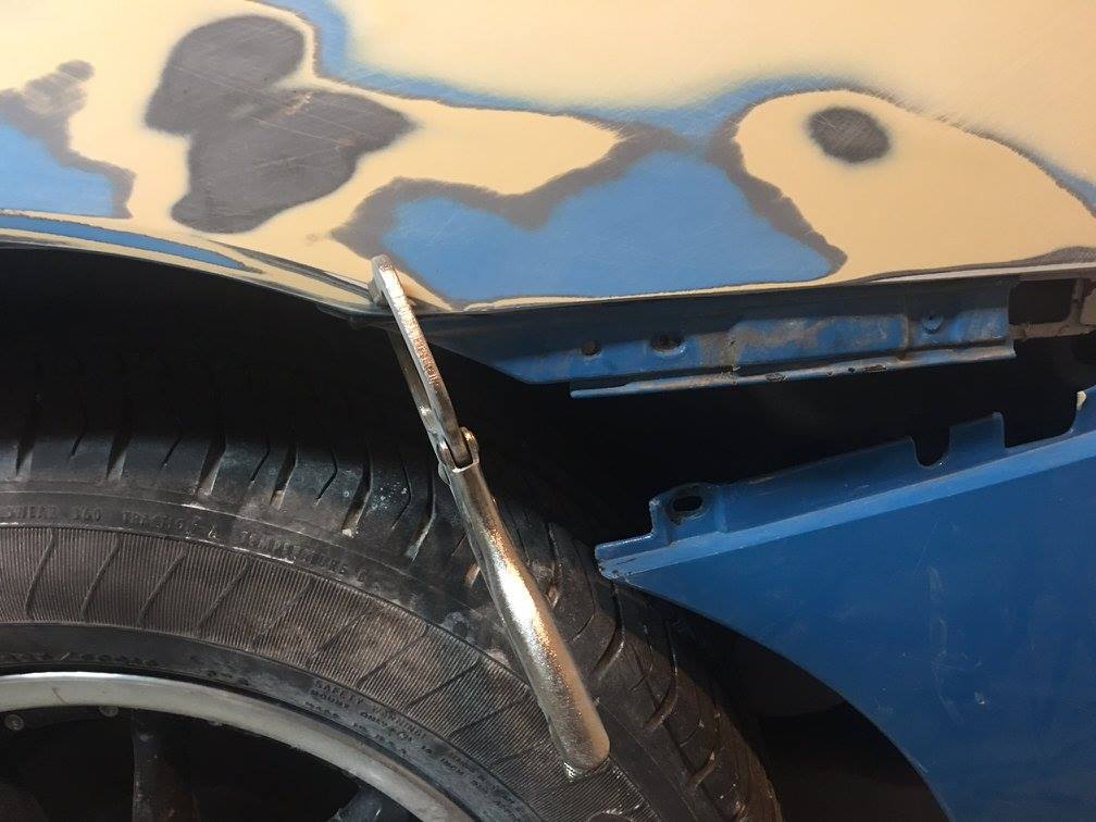
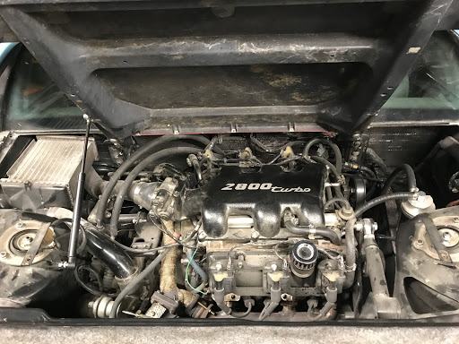
And here are a couple pictures of the turbo in place:


I was able to reuse a lot of the piece from last turbo setup on the charge piping and intercooler and had the set up going fairly quickly:


So as of right now the car has been getting tuned and tweaked and the turbo set up is doing quite well, boost quite nicely and makes awesome noises, as the video alex posted shows. Now the next step that is causing issues is I am experiencing boost creep due to the undersized turbo, running a 2.8l on a turbo meant for a 2.0 isn't ideal, but I wasn't planning large boost levels and the turbo can flow 400hp worth of flow, so Im not worried. I will be pulling the turbo to port the exhaust manifold and waste gate ports to help reduce the creep, right now I hit 6psi by about 1500-1800rpms and by 4000rpms I start gaining a pound of boost every few hundred rpms until I hit 11-12psi and I let off before it gets out of hand 

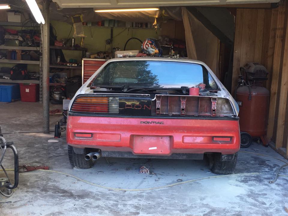
So hopefully you guys enjoyed the antics Ive been through, it can get frustrating at times, but as somebody who has daily driven fieros for year and then been out of them for years I am really enjoying my time back in one!

awalker
awalker New Reader
1/23/19 8:43 a.m.

https://youtu.be/nPY4Dz1btJM

Here are some turbo noises for your viewing pleasure


1 2

You'll need to log in to post.

Our Preferred Partners
vksvVLCEzDslMpFz78UH5J4bCWoKt7MQKxhMu2A8uF4vCGEmcCgTsJQZJ2VZMAmv