1 ... 4 5 6 7 8
WondrousBread
WondrousBread Reader
9/5/22 8:59 p.m.

When I first installed the Megasquirt (and a bit later on) I mentioned some issues with sync loss. I was able to mitigate the issues by adjusting the VR pots and re-gapping the pickups, but every so often I would get a couple of lost syncs on the datalog with no apparent reason. Then the other day I noticed that sometimes at high RPM it would lose sync and then have trouble re-establishing it for a few seconds at a time.

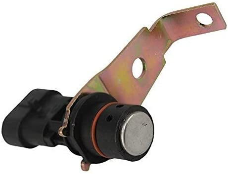
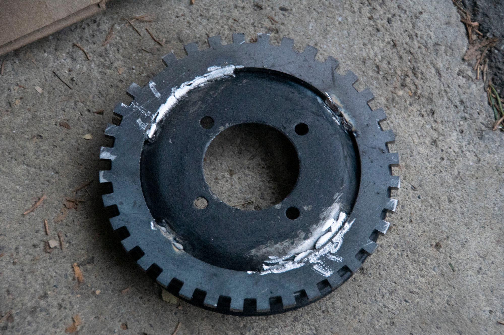
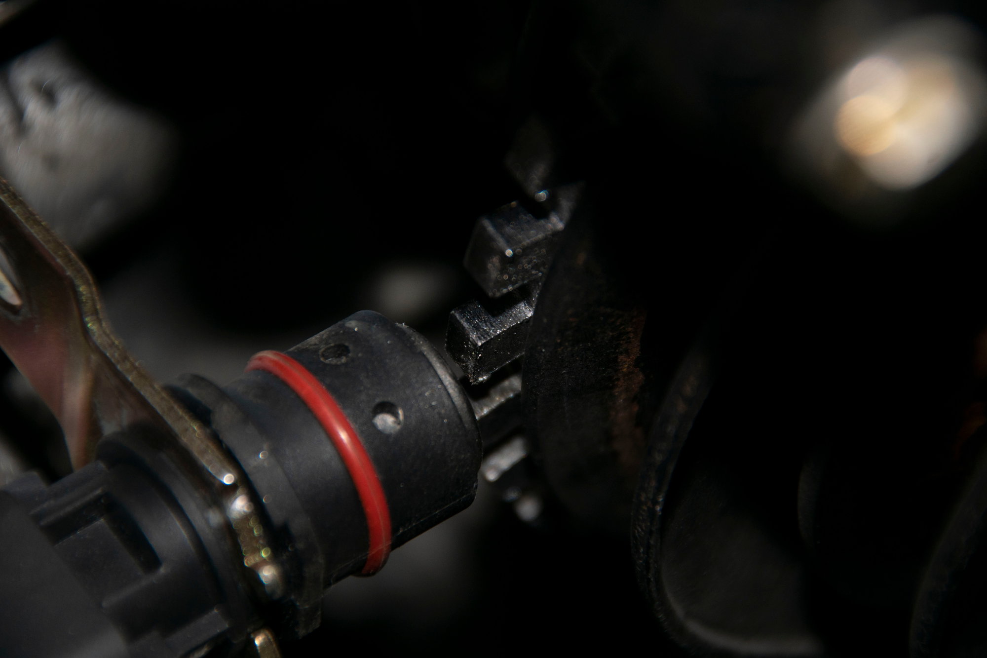
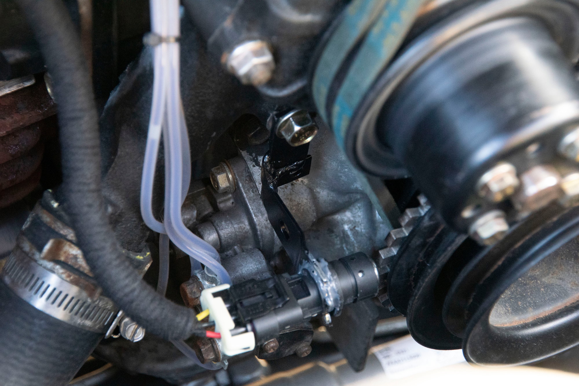
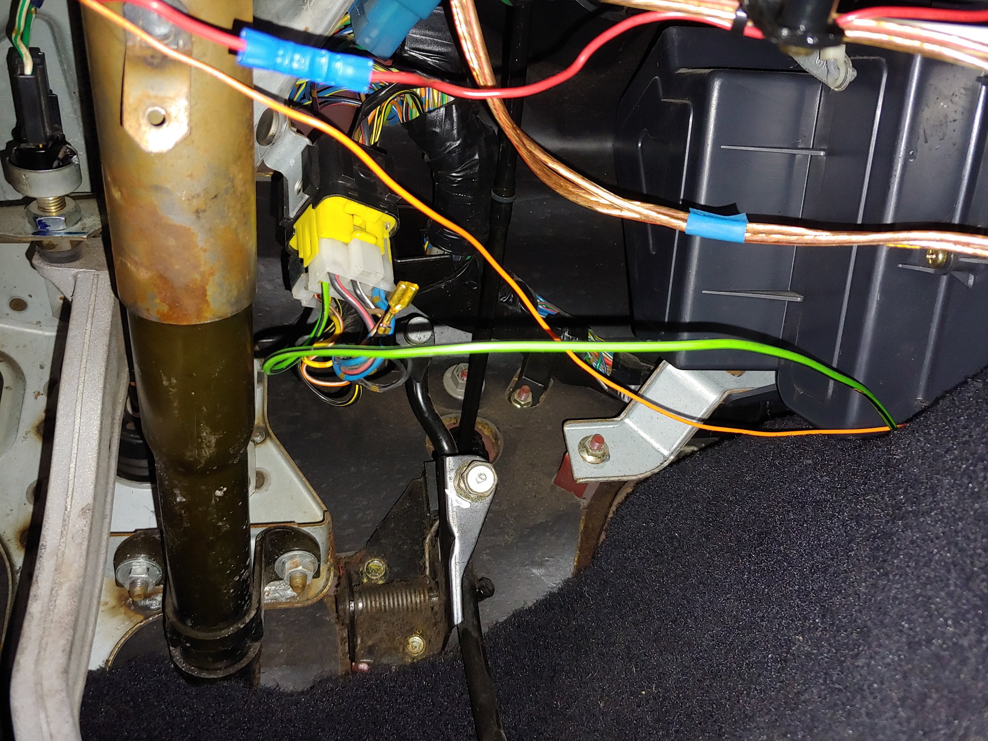
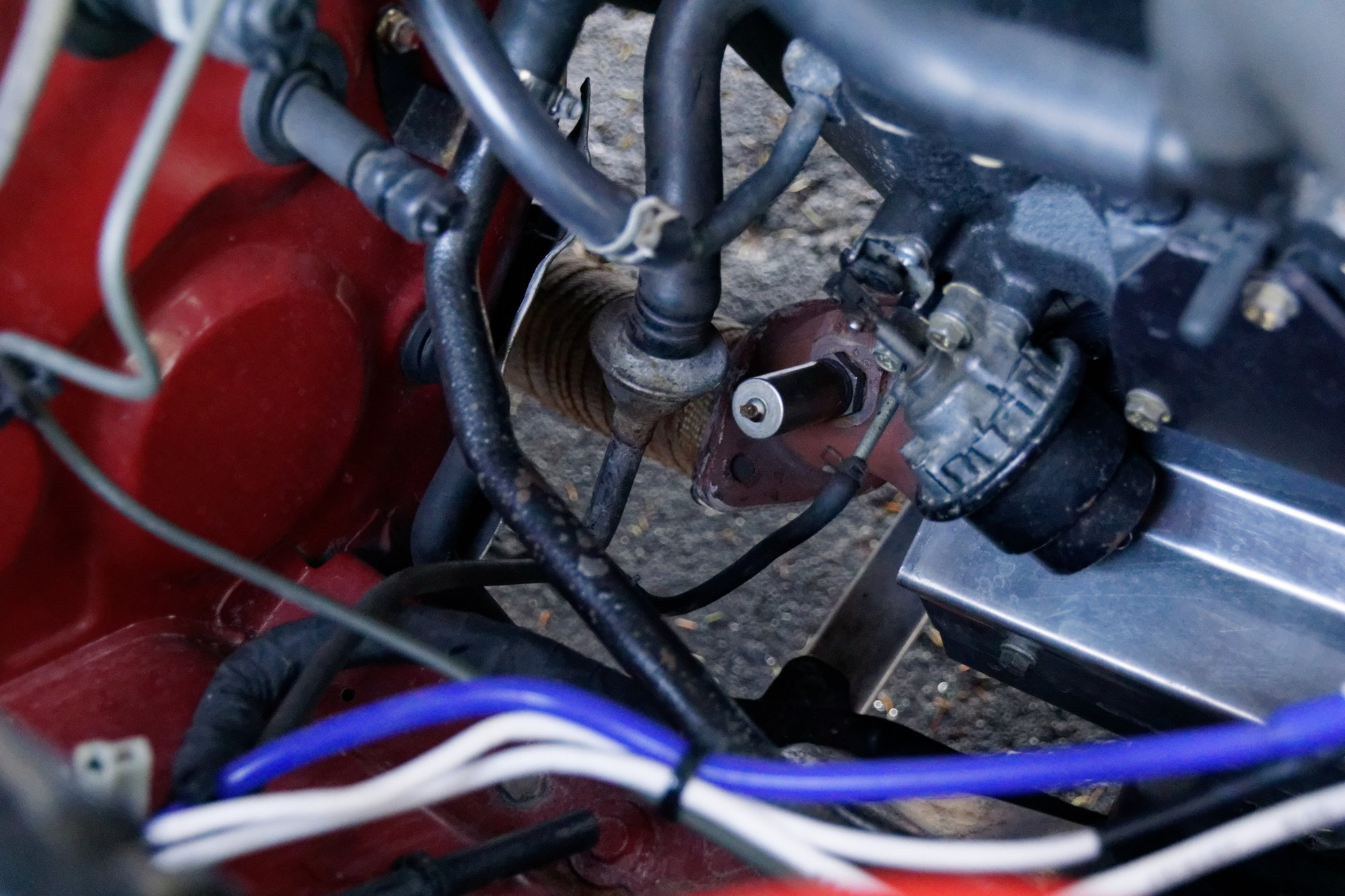
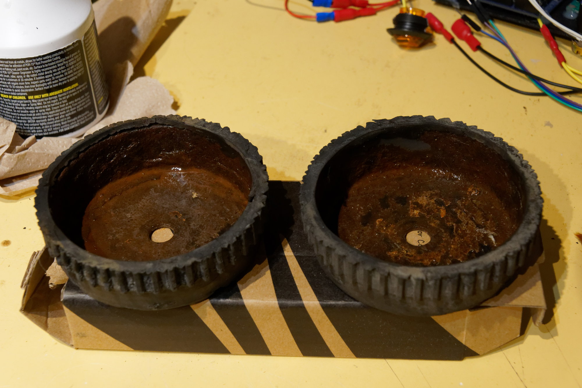
Here's the stock CAS:


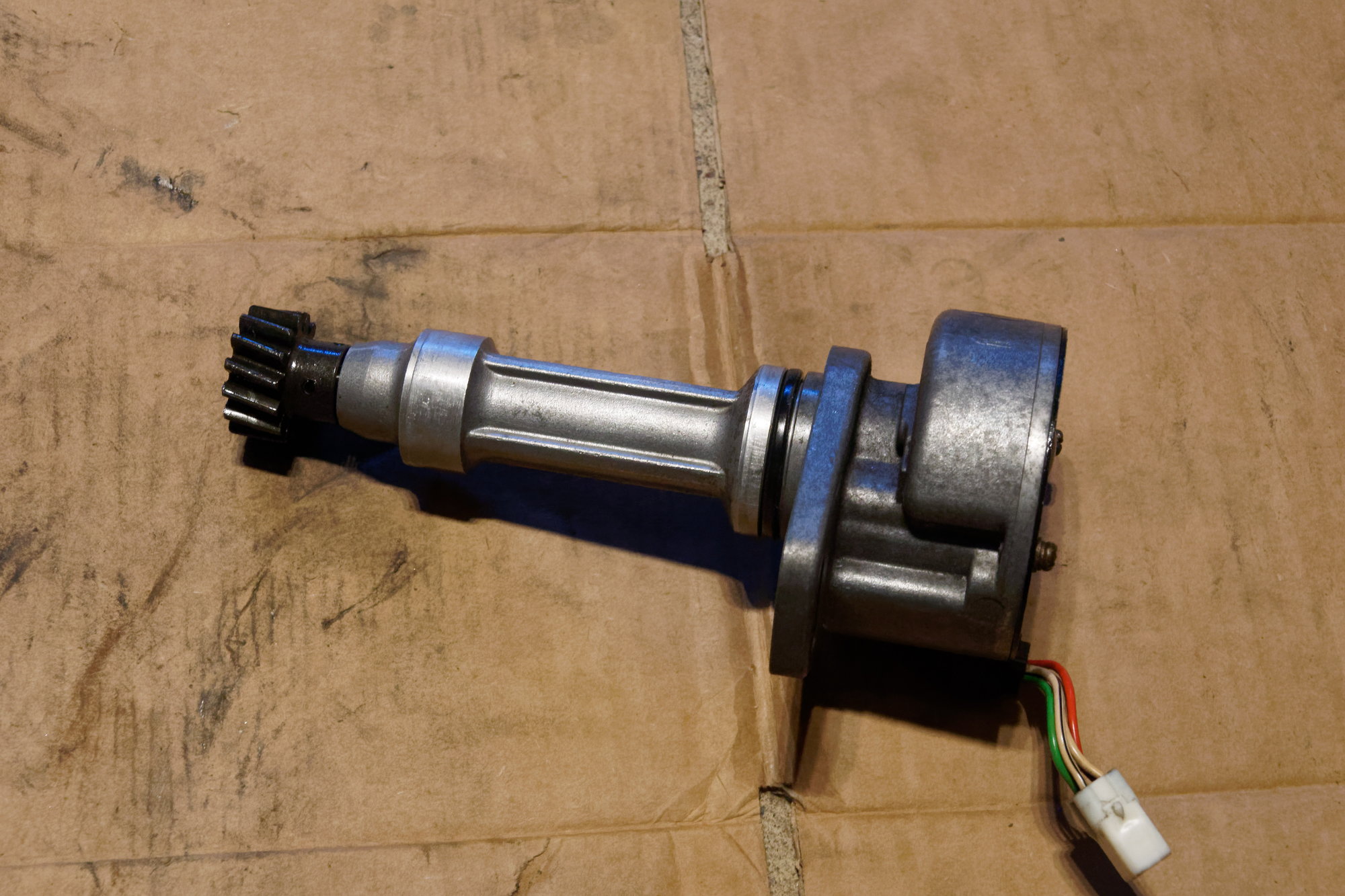
The wheel I was losing sync on is the upper "cam" wheel. I wasn't able to determine the reason, and despite some fiddling with the pickup gap I wasn't able to completely eliminate the issue. I ordered a small 36-1 wheel and hall sensor with the idea that I could mount them in the CAS itself and avoid modifying the front pulleys, but then when I was asking about it in the Rx7Club's Megasquirt section, member Nosferatu had some really helpful advice. Apparently you can just modify the CAS into a 24-2 wheel and avoid using the upper wheel entirely.

So that's exactly what I did. I found several posts about it, but most were relating to the MS1 and didn't have very clear instructions. It turned out to be pretty straightforward though.

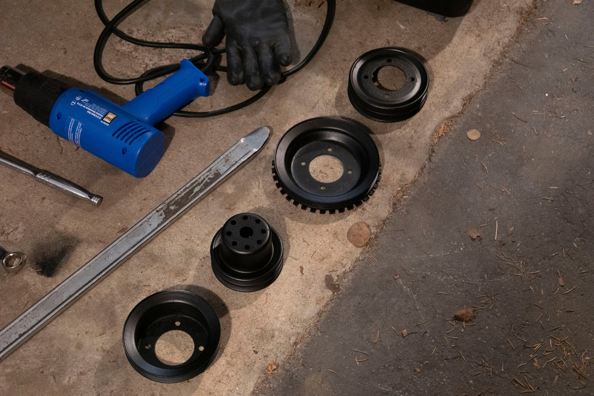
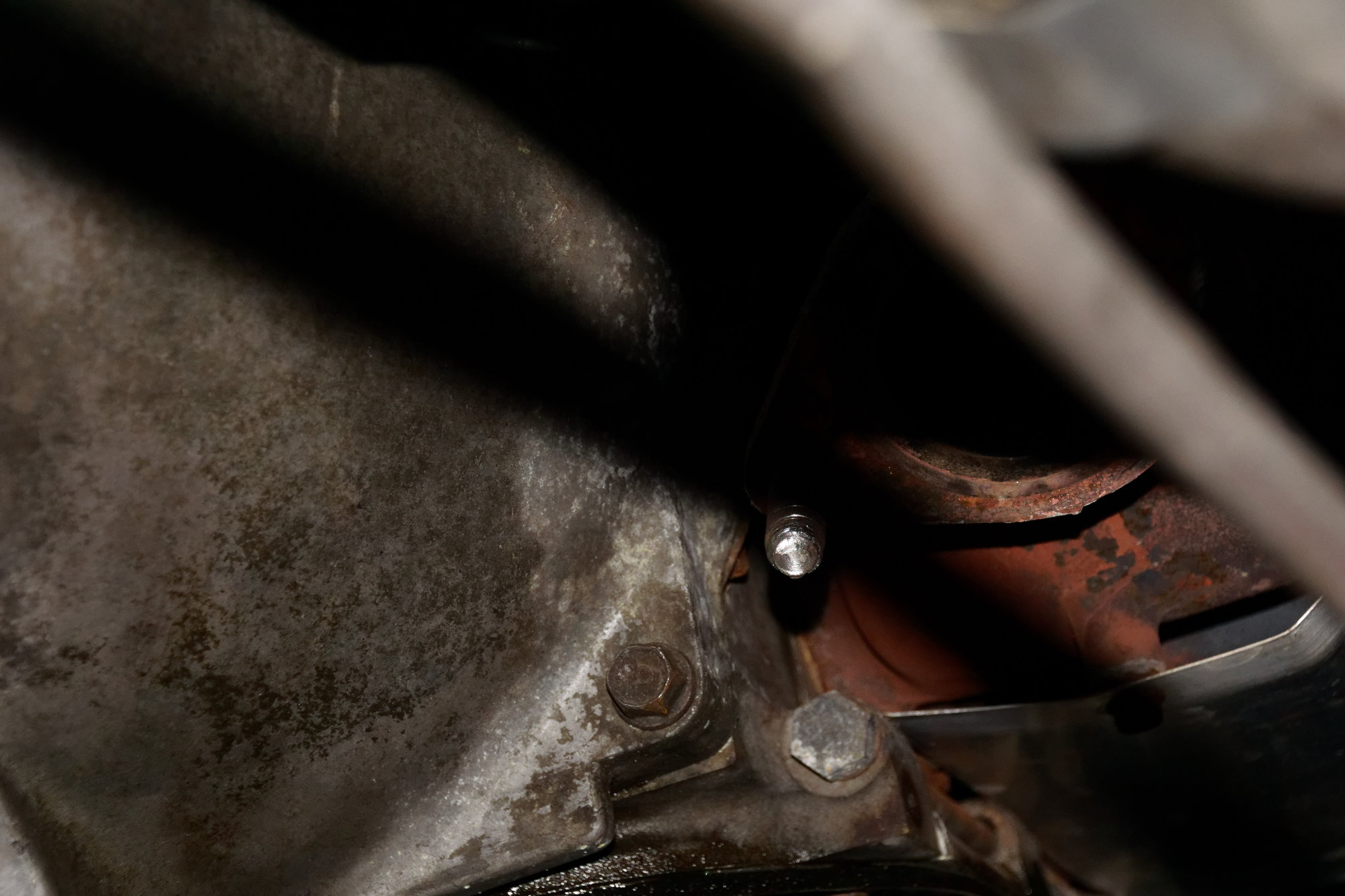
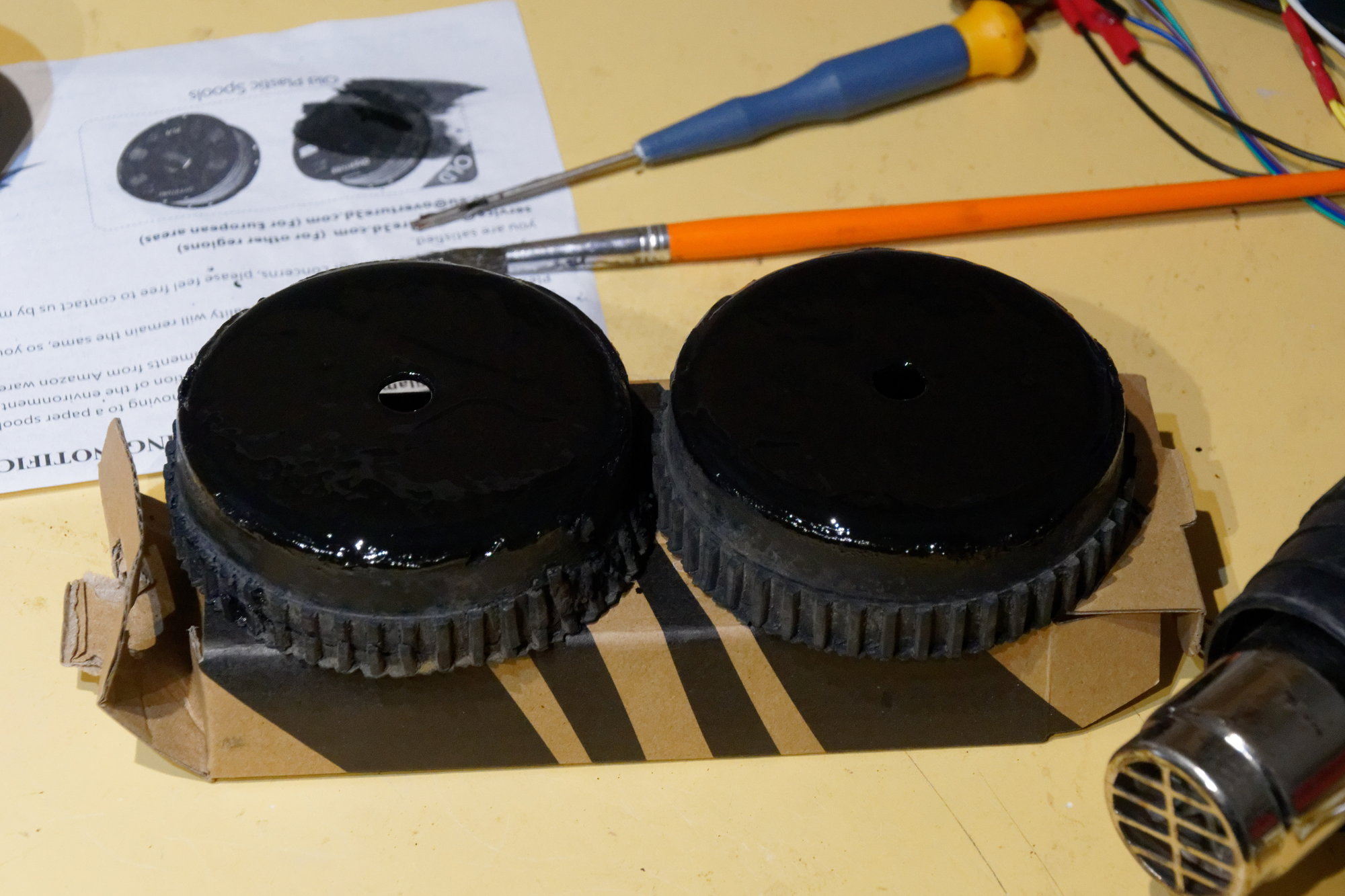
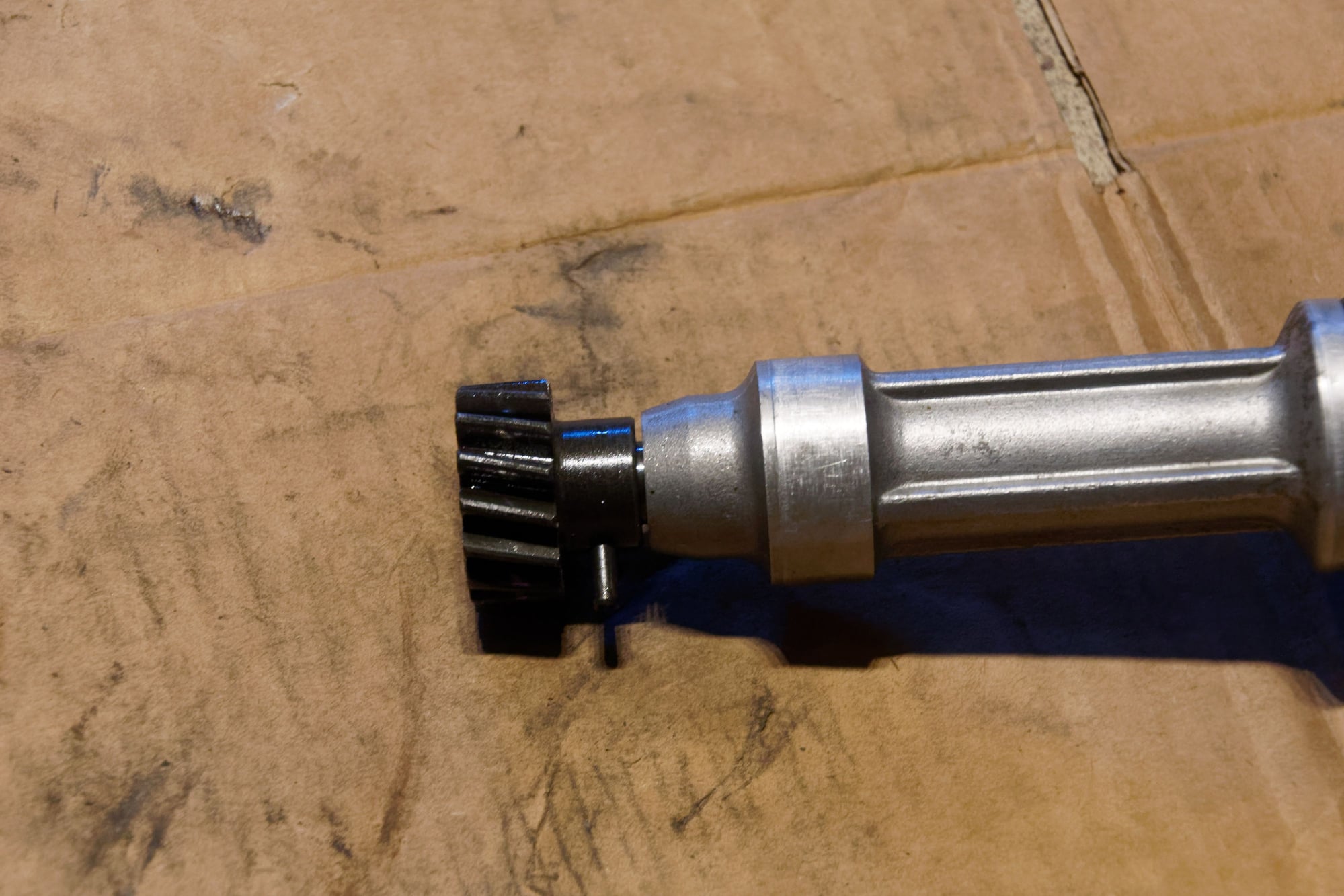
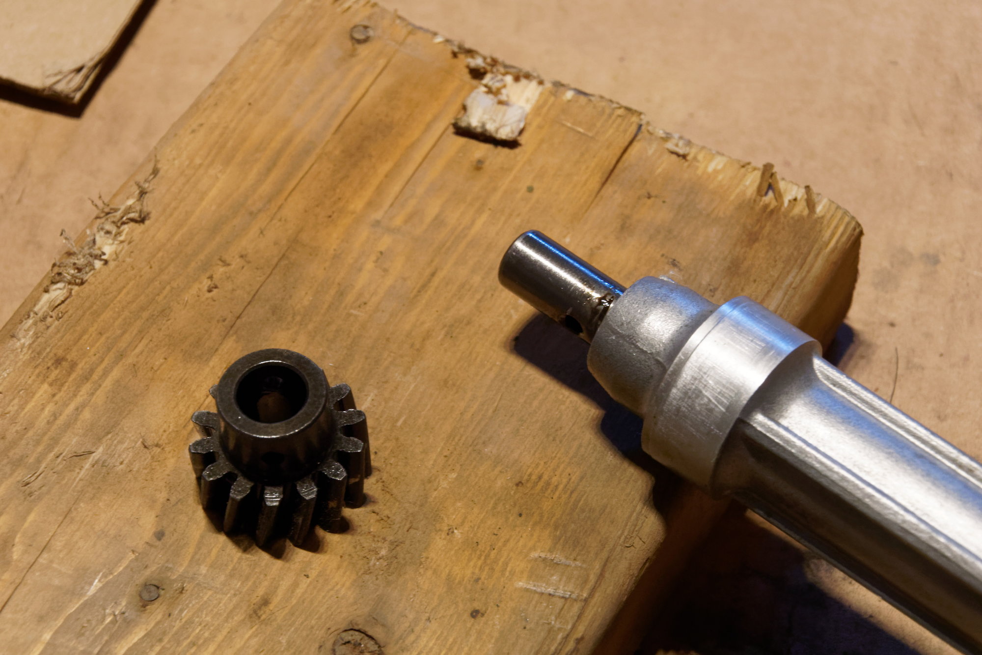
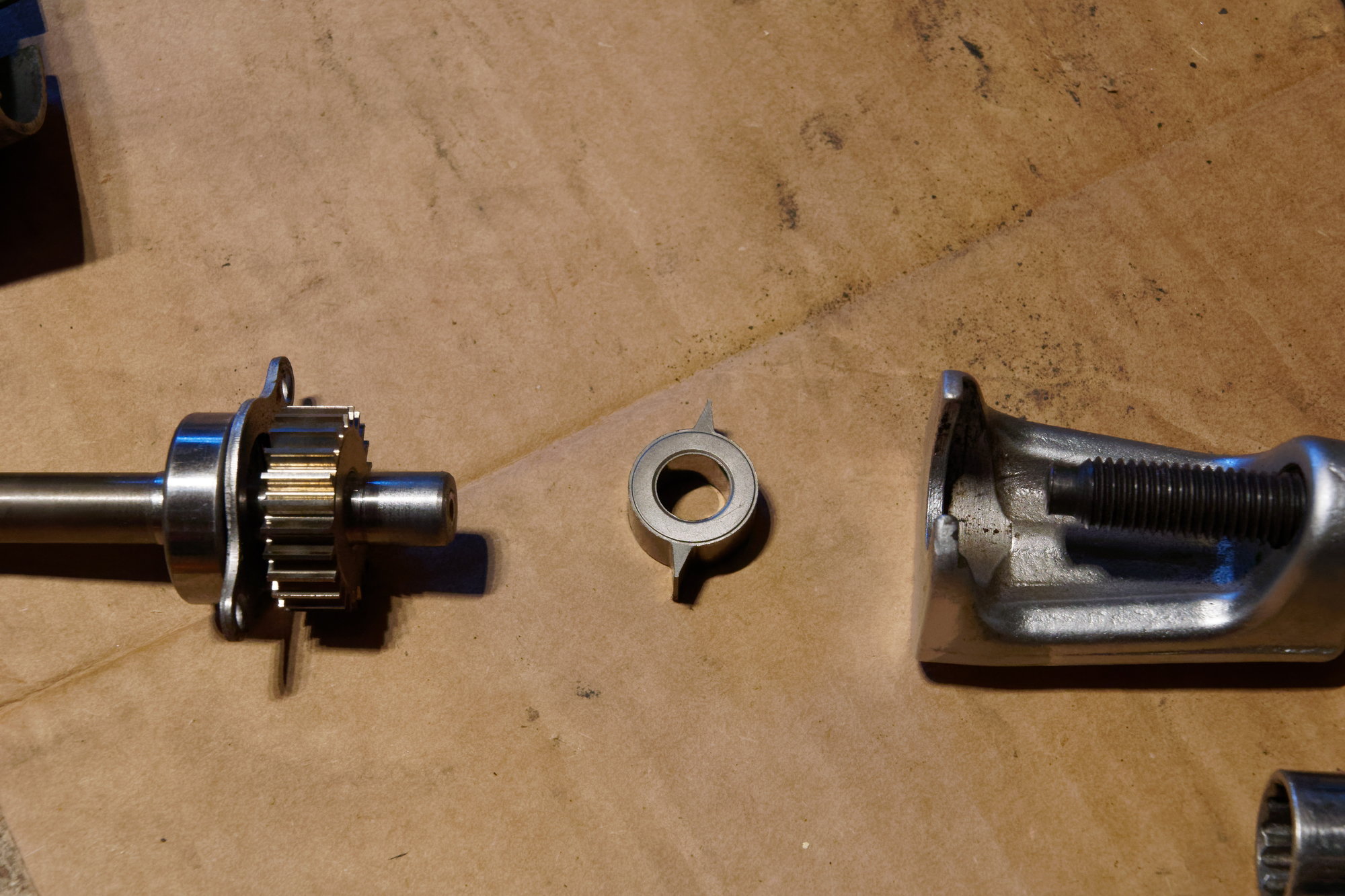
Remove the roll-pin and drive gear:


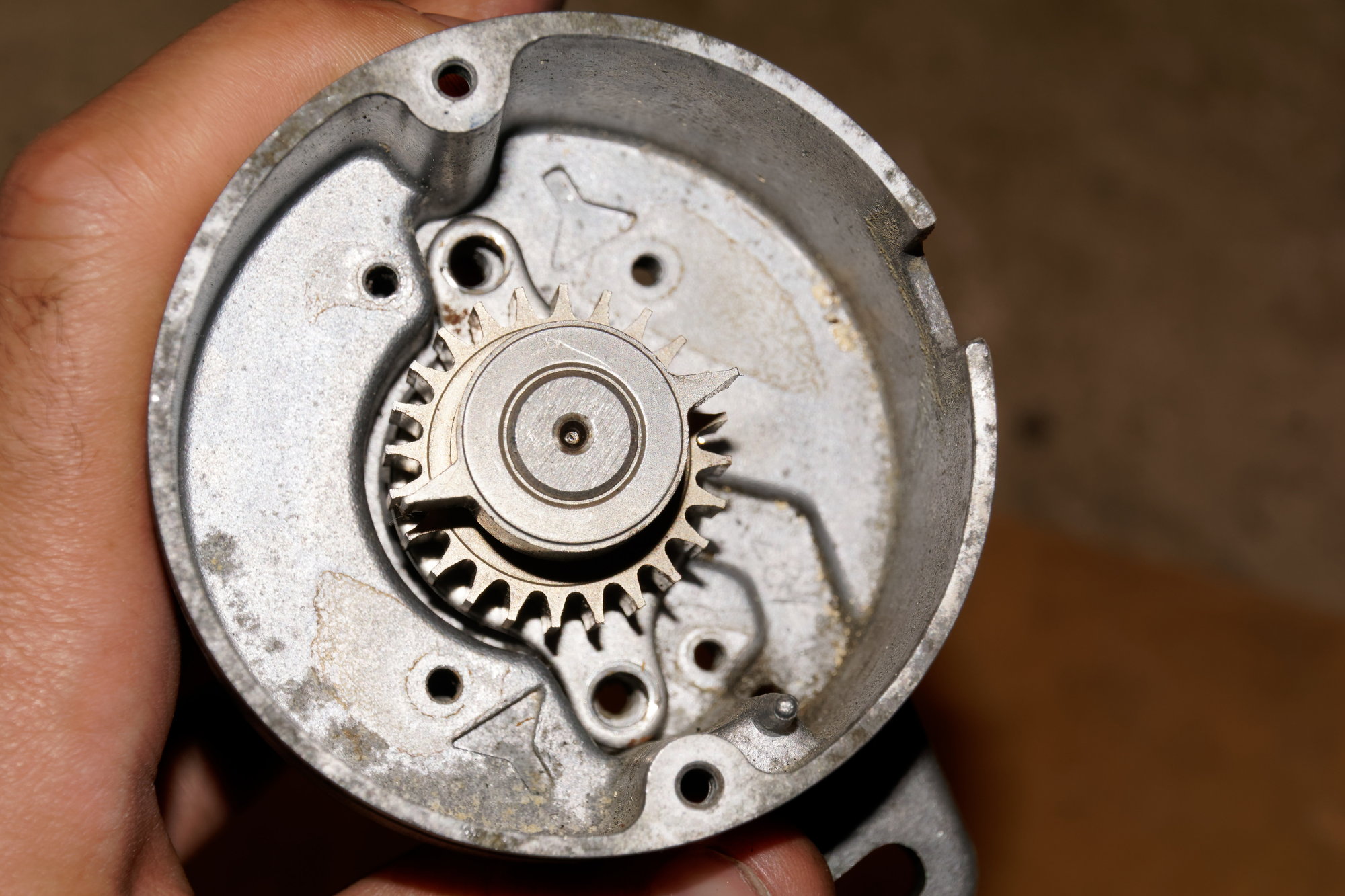
Take out the pickups, and the screws that hold the rotating assembly:
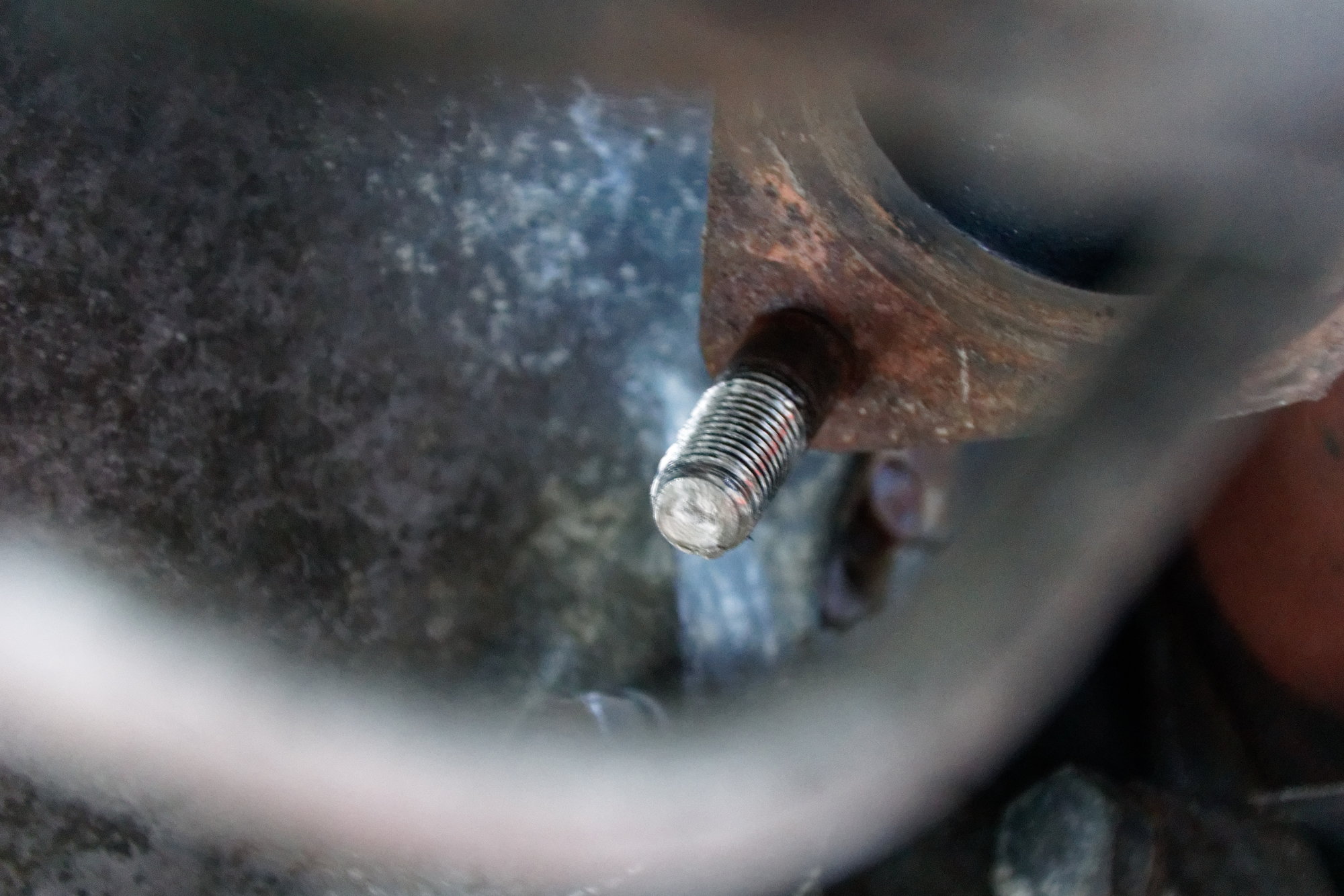


Pop out the shaft:


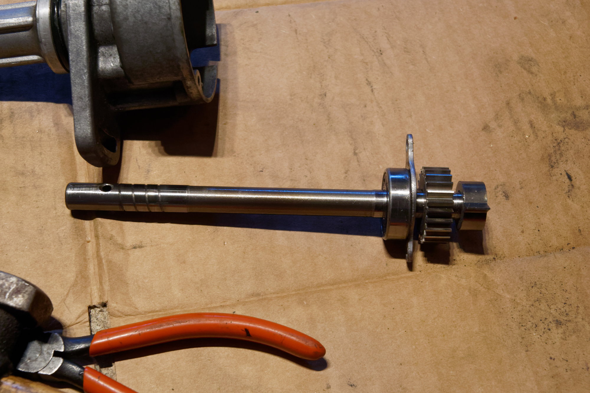
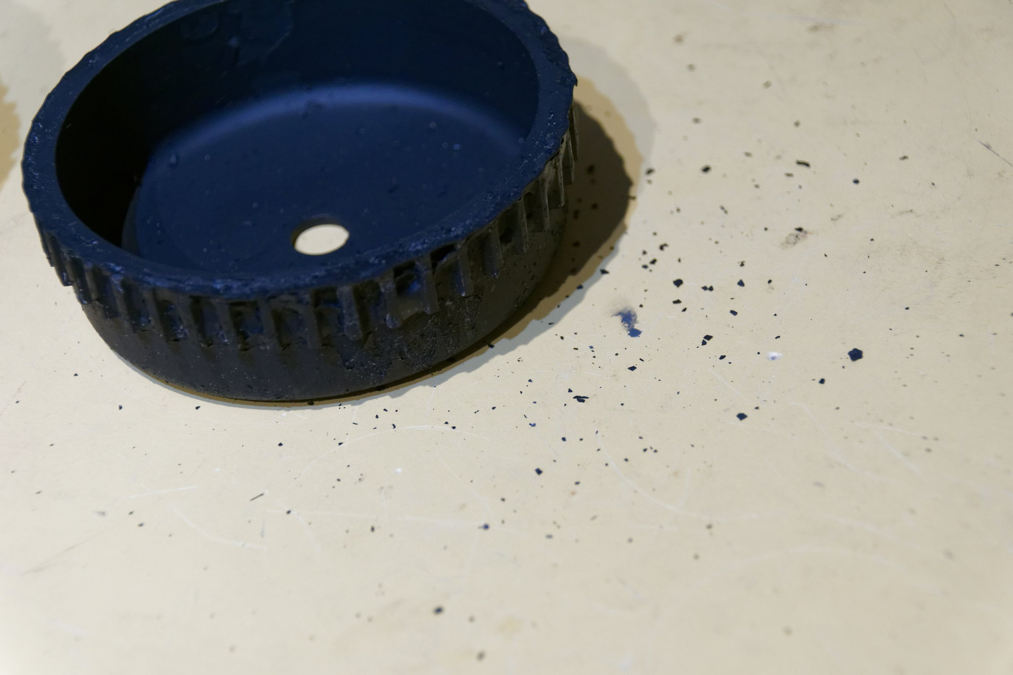
Removing the two-tooth wheel is optional, but this ball-joint puller made it a 2 minute job, so why not:


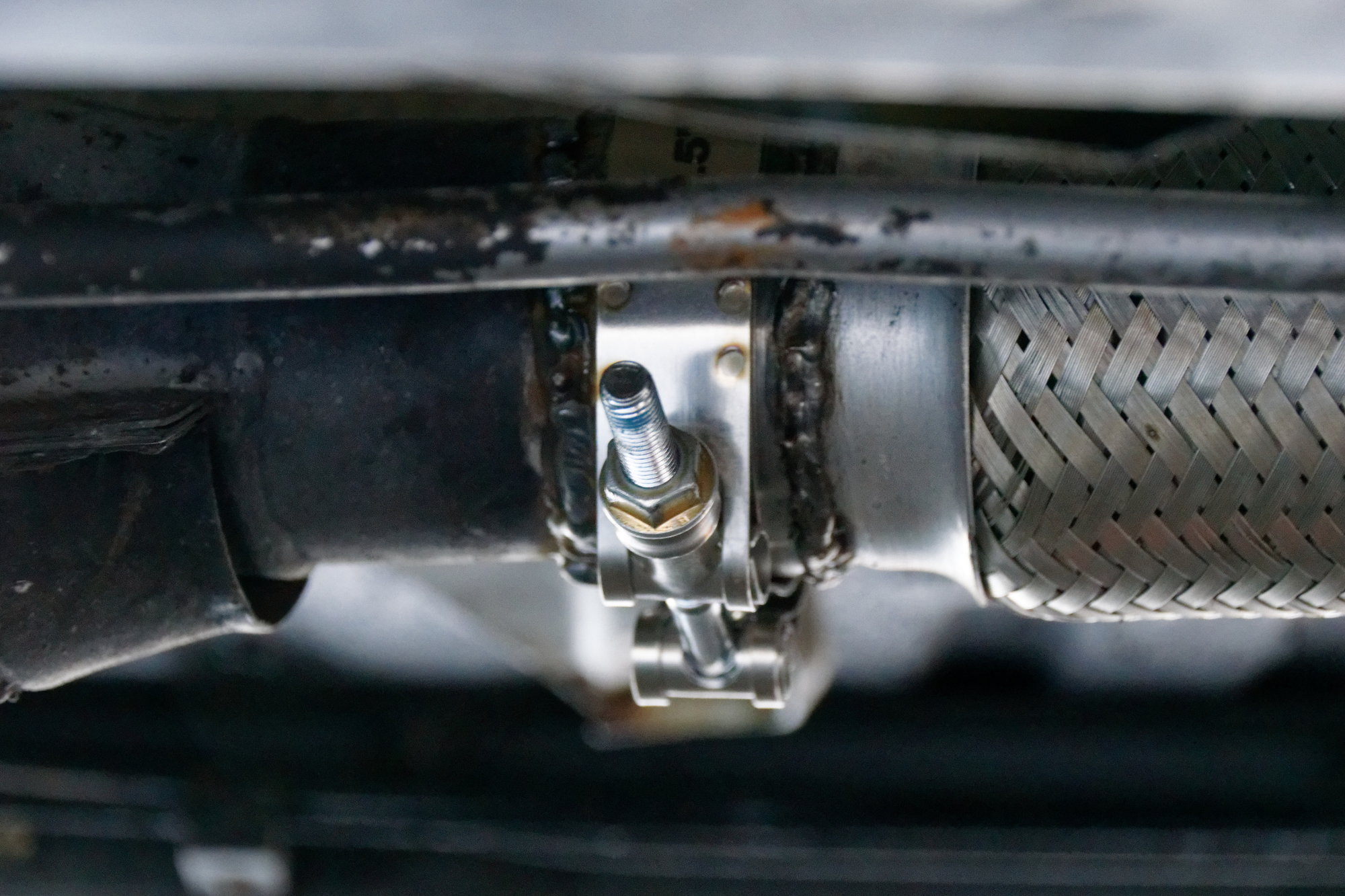
Then grind out two opposing teeth. I read first that it "didn't matter" which teeth you grind out as long as they are opposing. This is technically true, but the best way is to count back from the two-tooth wheel three teeth. There are instructions on this particular step if you search. The only consequence of my choosing the teeth at random is that I had to grind out the adjustment channel on the CAS body a bit to time the engine. Since I've already gone and modified this CAS, I'm not worried about it.

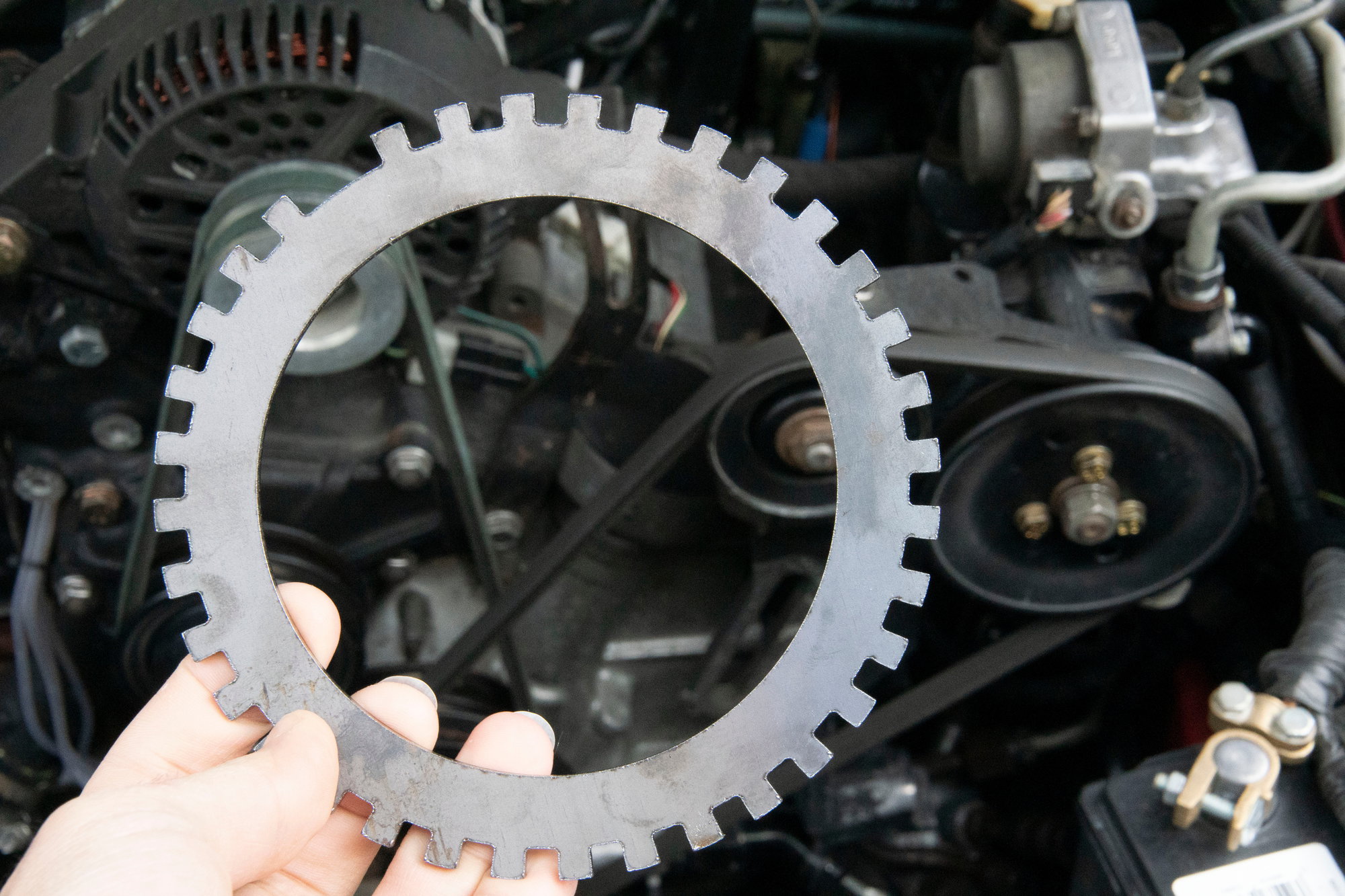
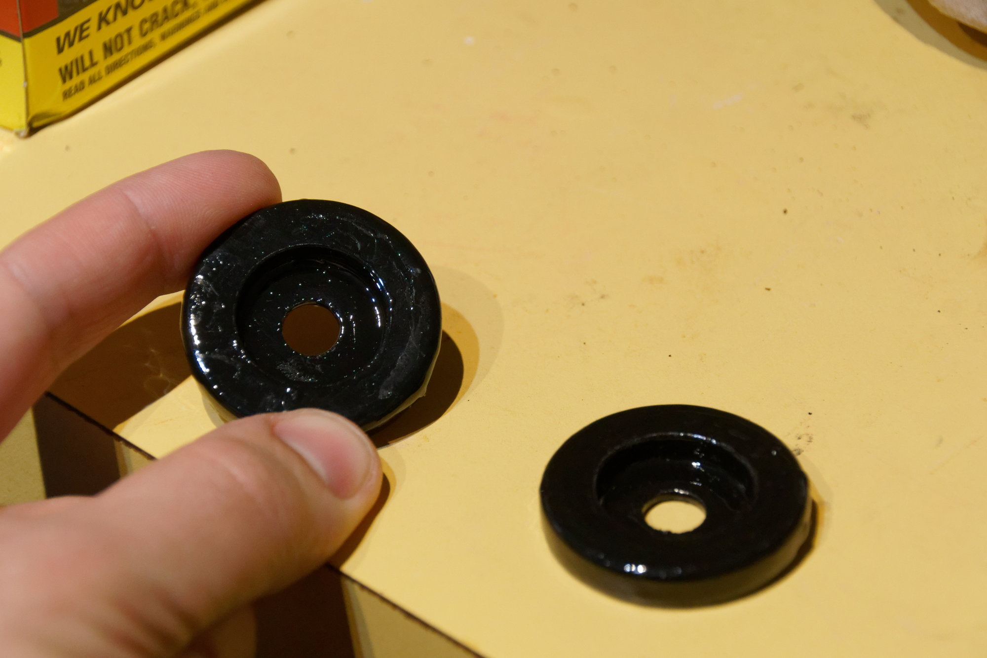
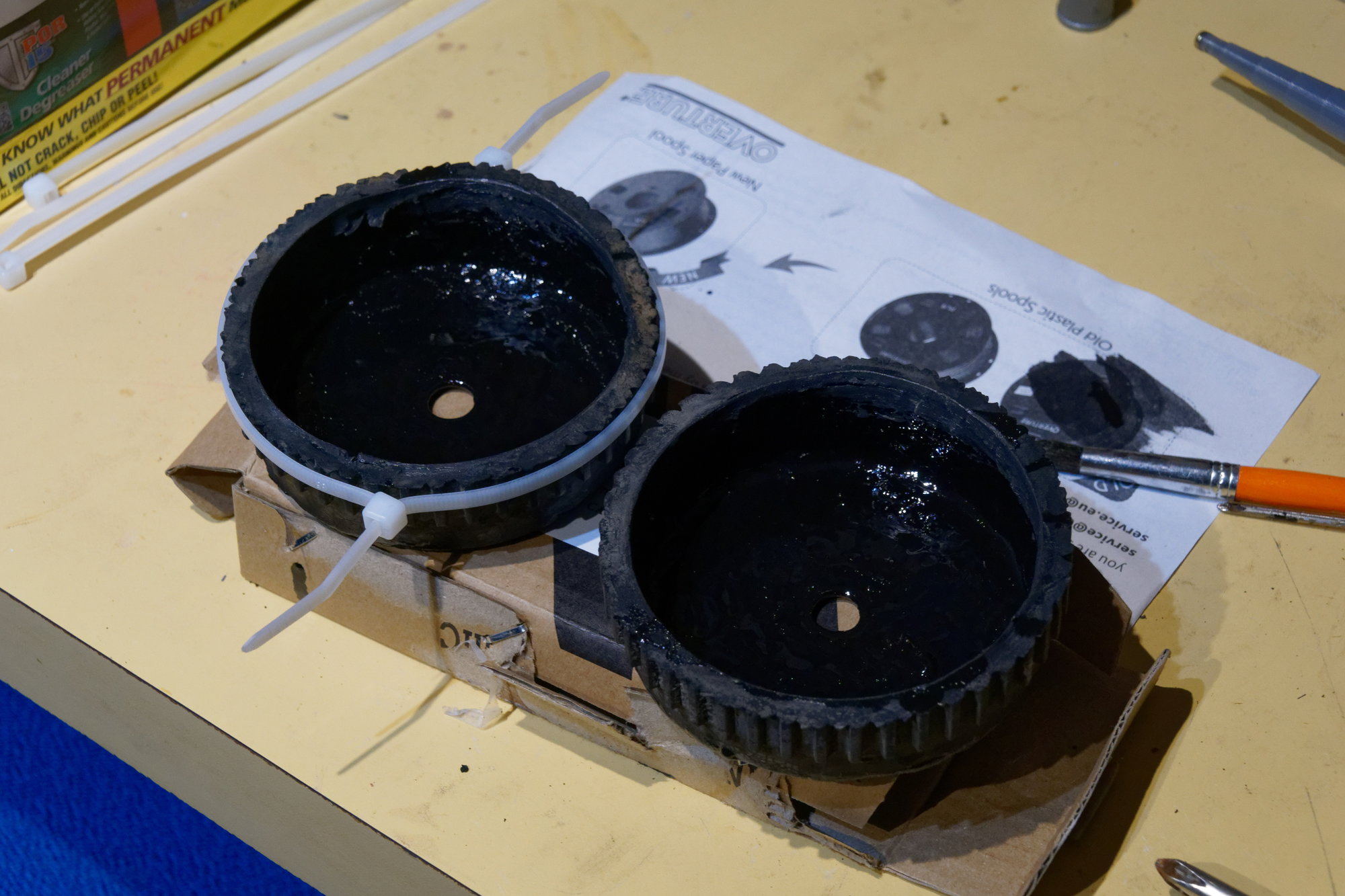
Time to put the CAS back together with its new 24-2 wheel:


I did accidentally kiss the next tooth over with the carbide burr, but it hasn't caused any issues in operation since it's a minor mark. Be careful though, if too much damage is done the tooth won't read anymore.

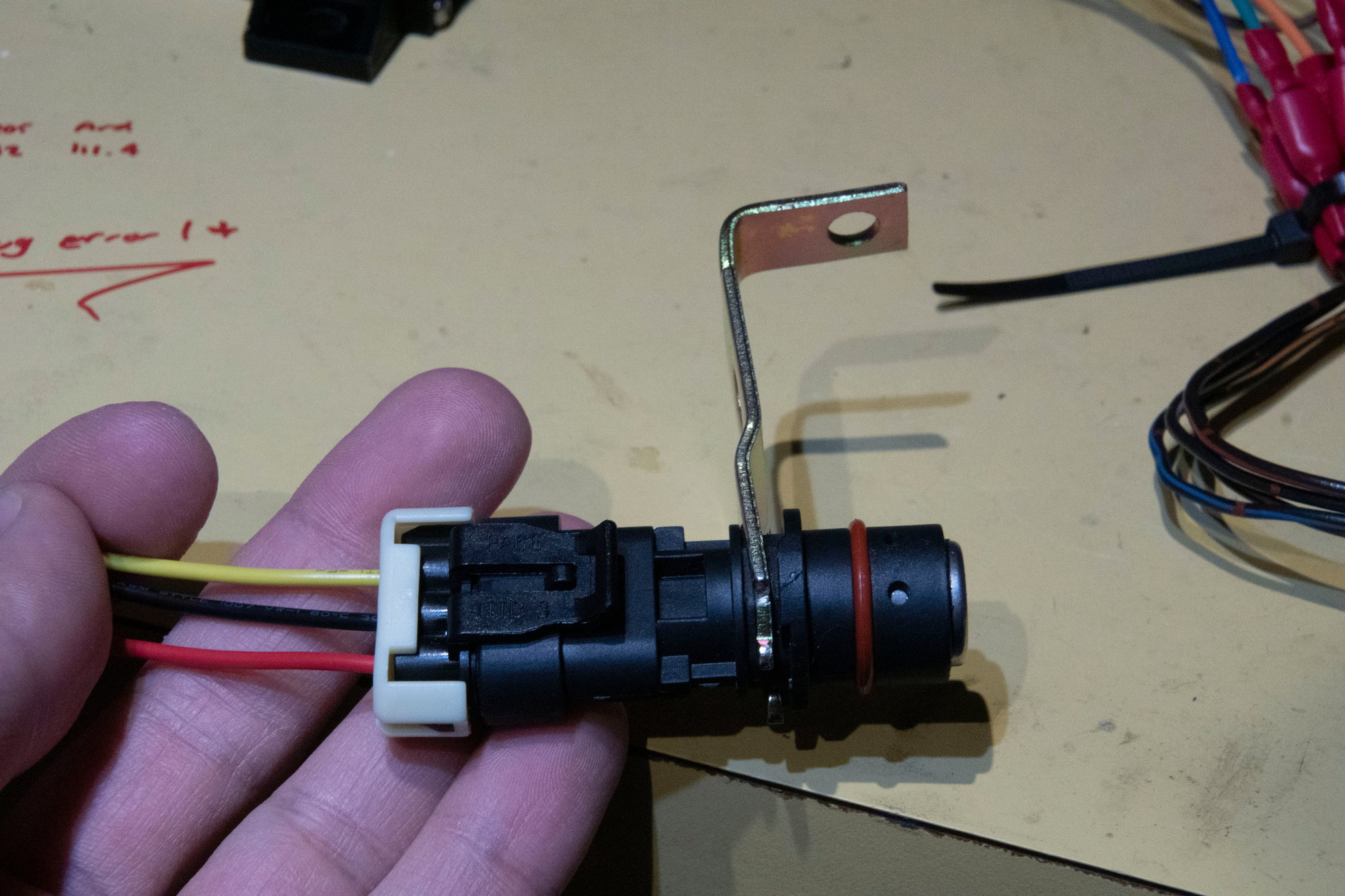
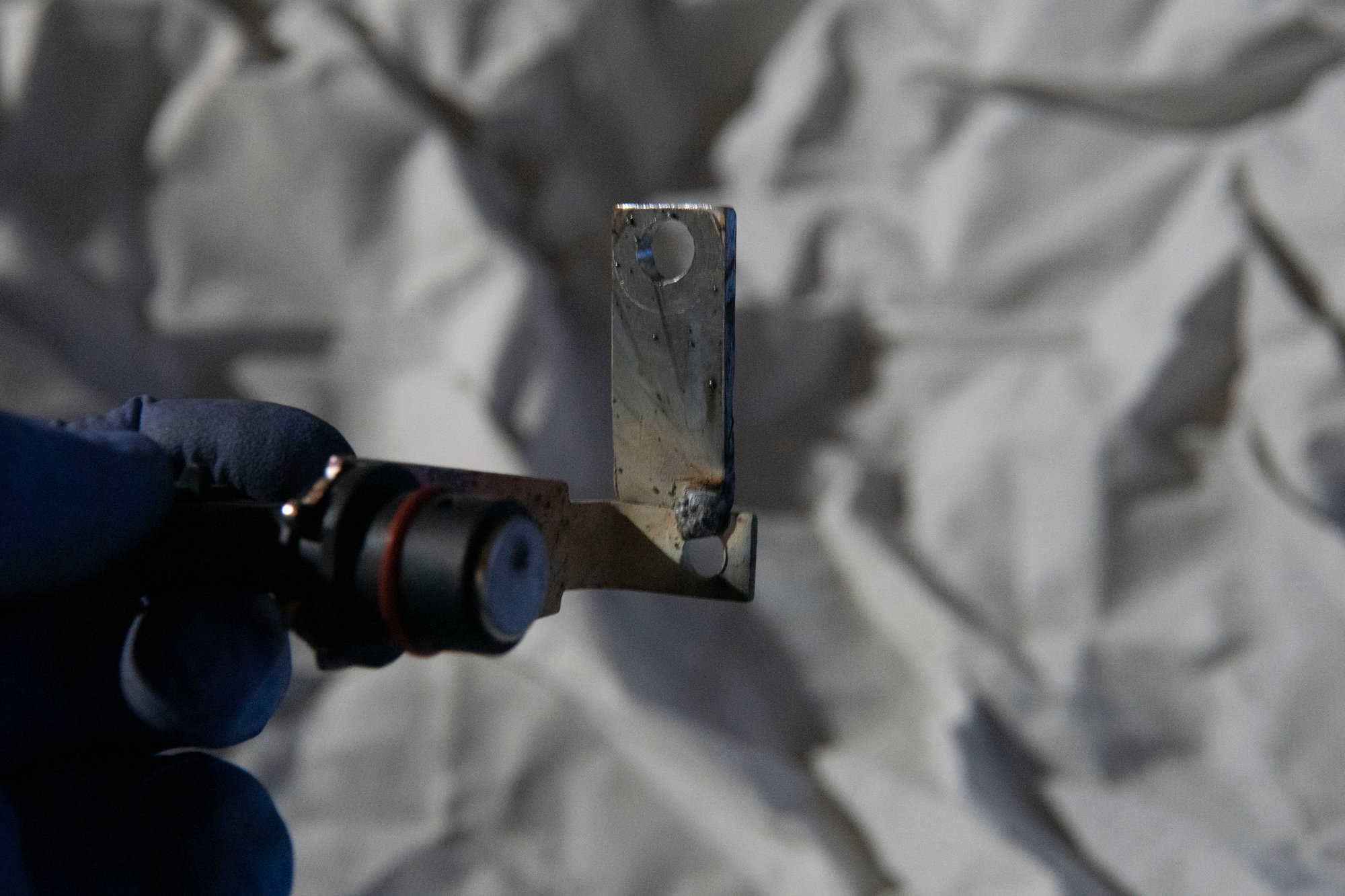
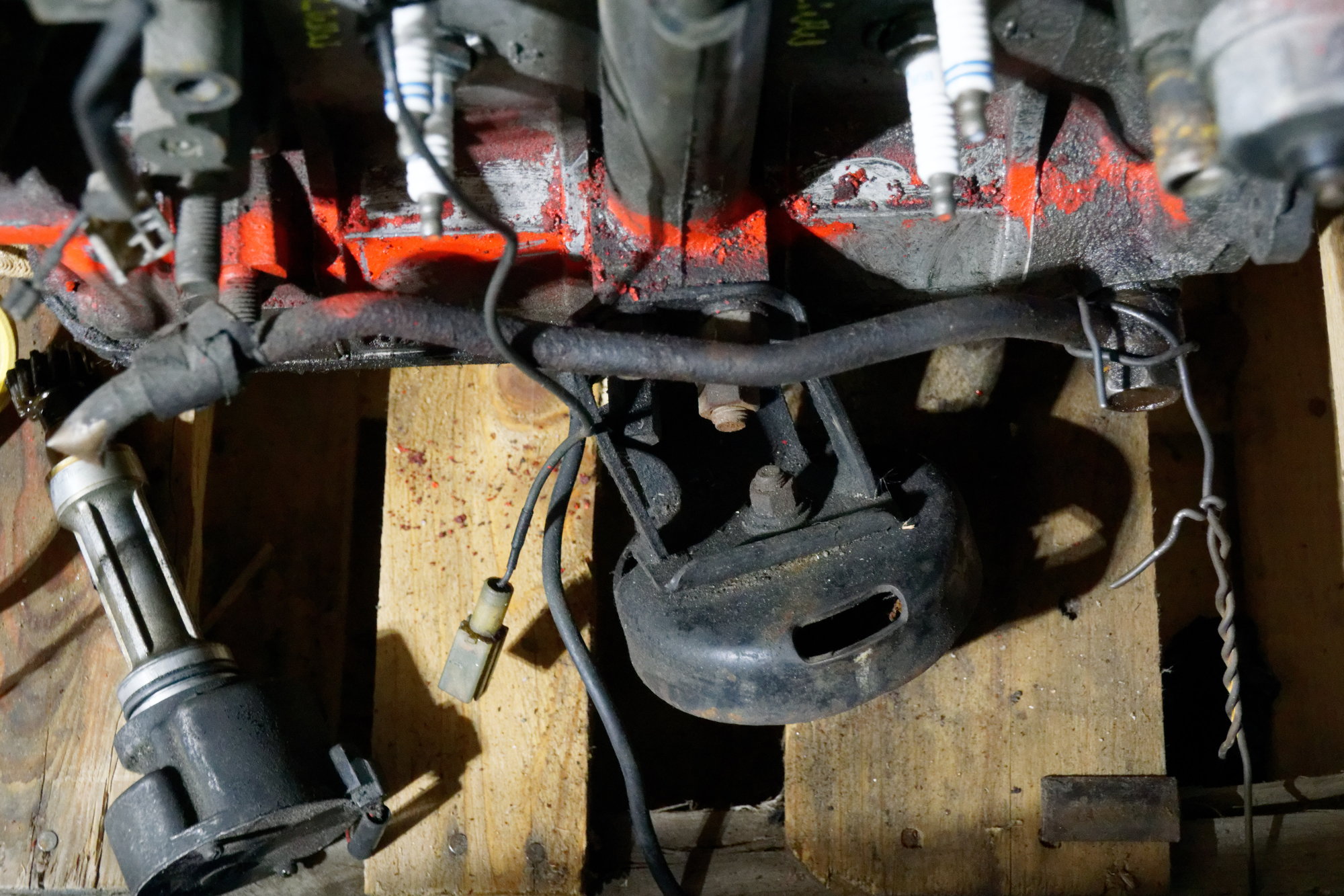
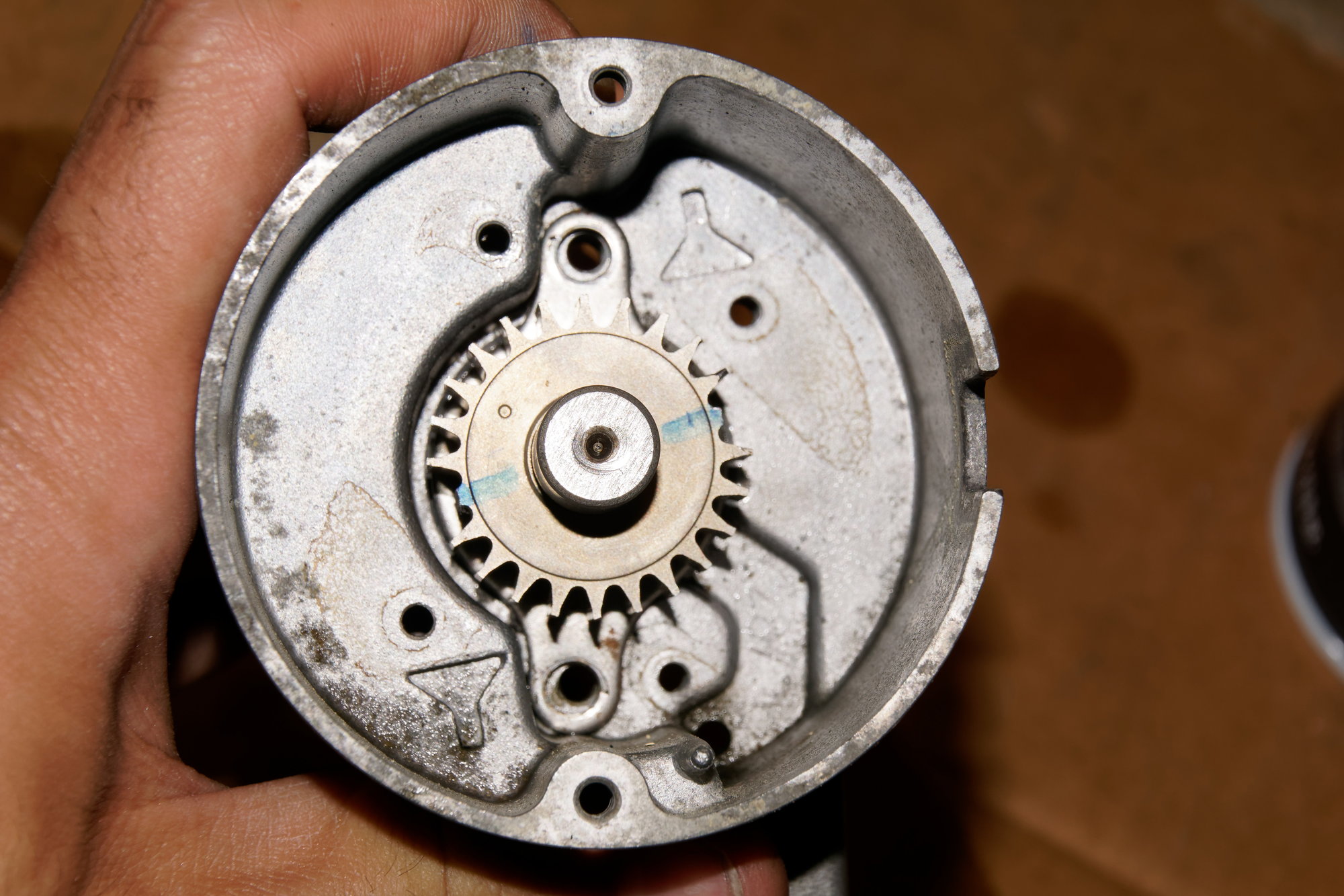
I technically don't need the extra pickup anymore, but couldn't think of a better place to store it than in the CAS. If I need a spare, I'll know exactly where to find it. I also added a dab of red paint to the third tooth back, since that's how the engine is timed now:


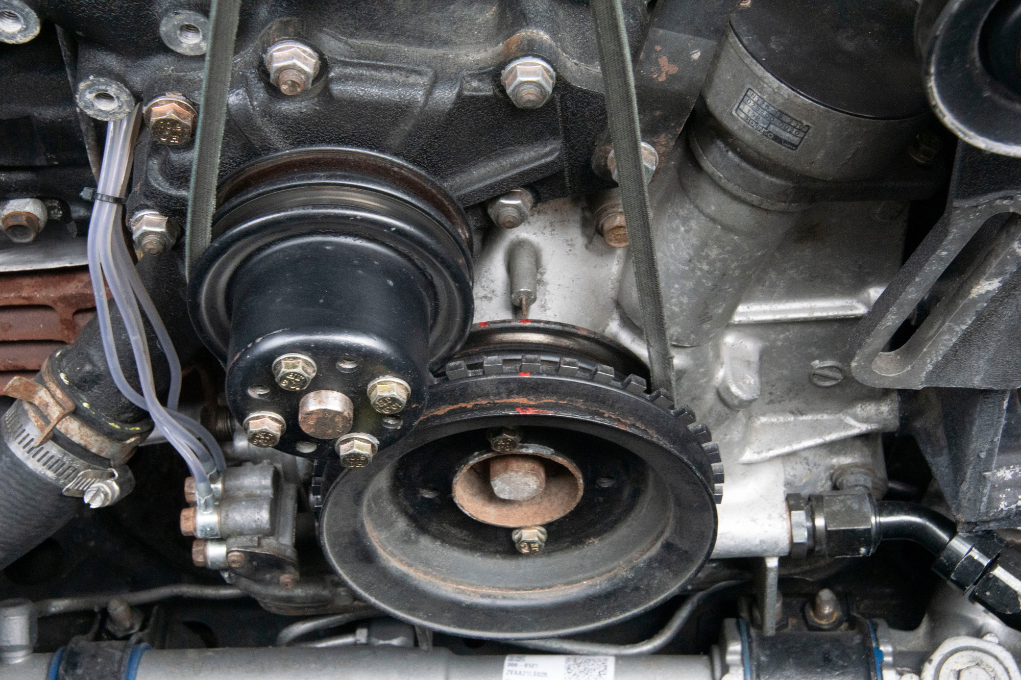
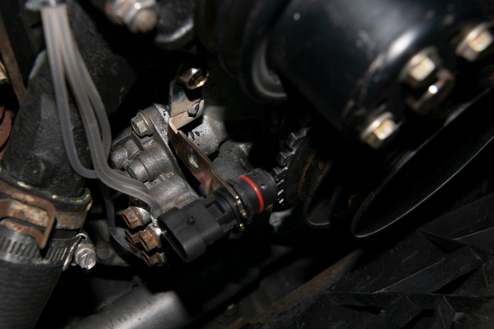
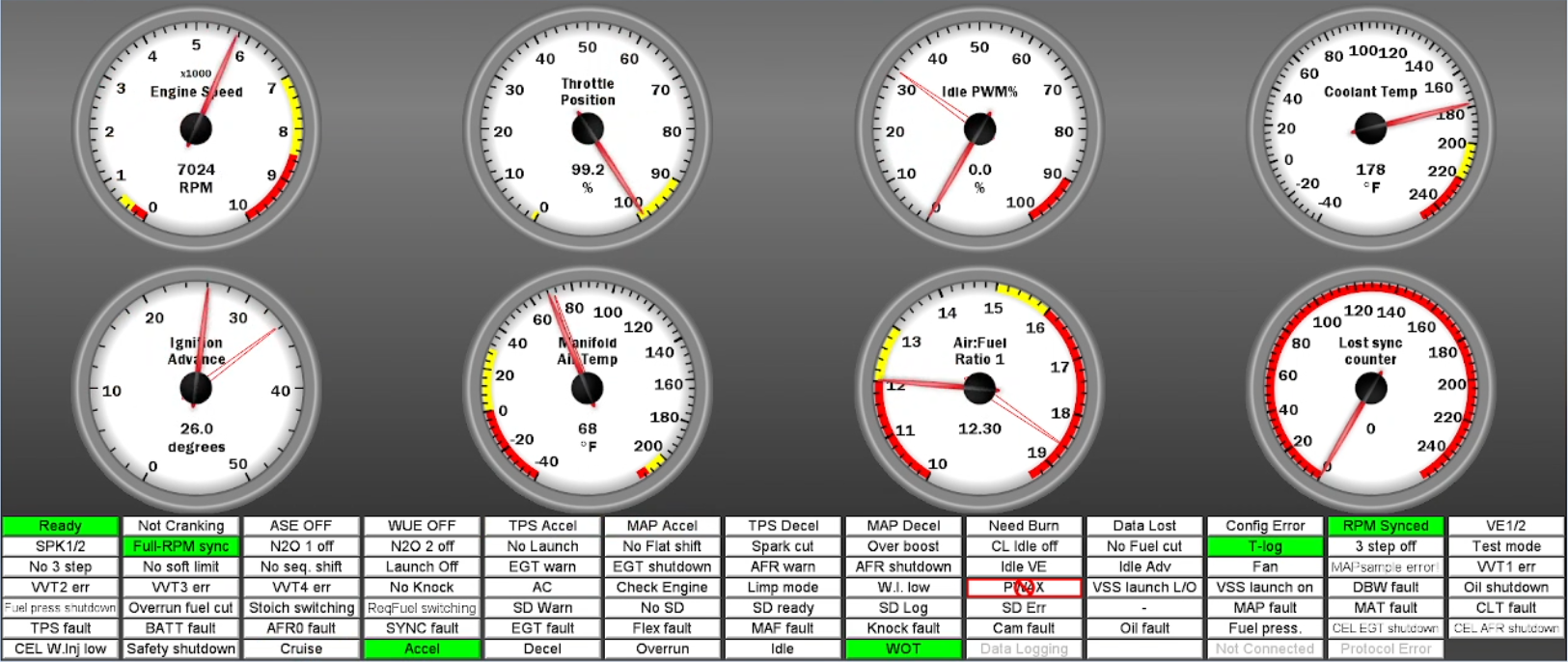
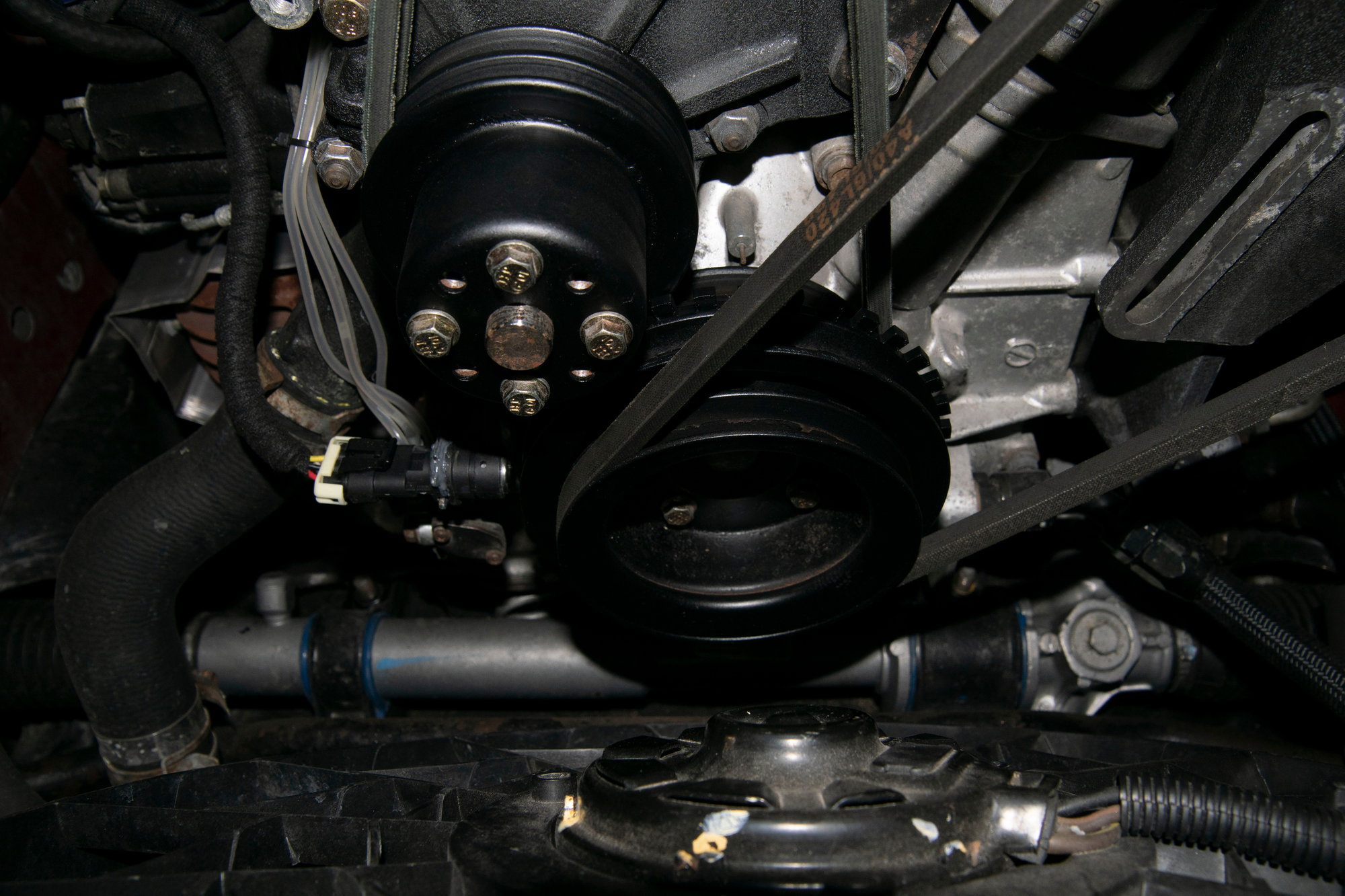
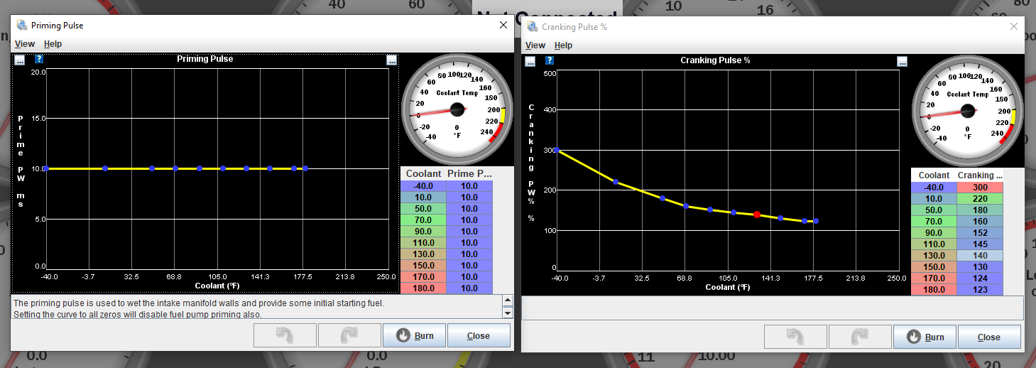
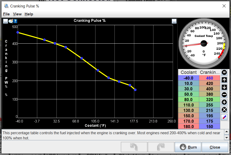
Then I put the engine at TDC, lined up the gears, and installed the CAS. Altering my sensor settings in Tunerstudio took a few tries, but I got it working and timed. After a test drive and re-gapping the pickup to .011", perfect sync. No loss during cranking, no loss at high rpm, no loss when the fan turns on.

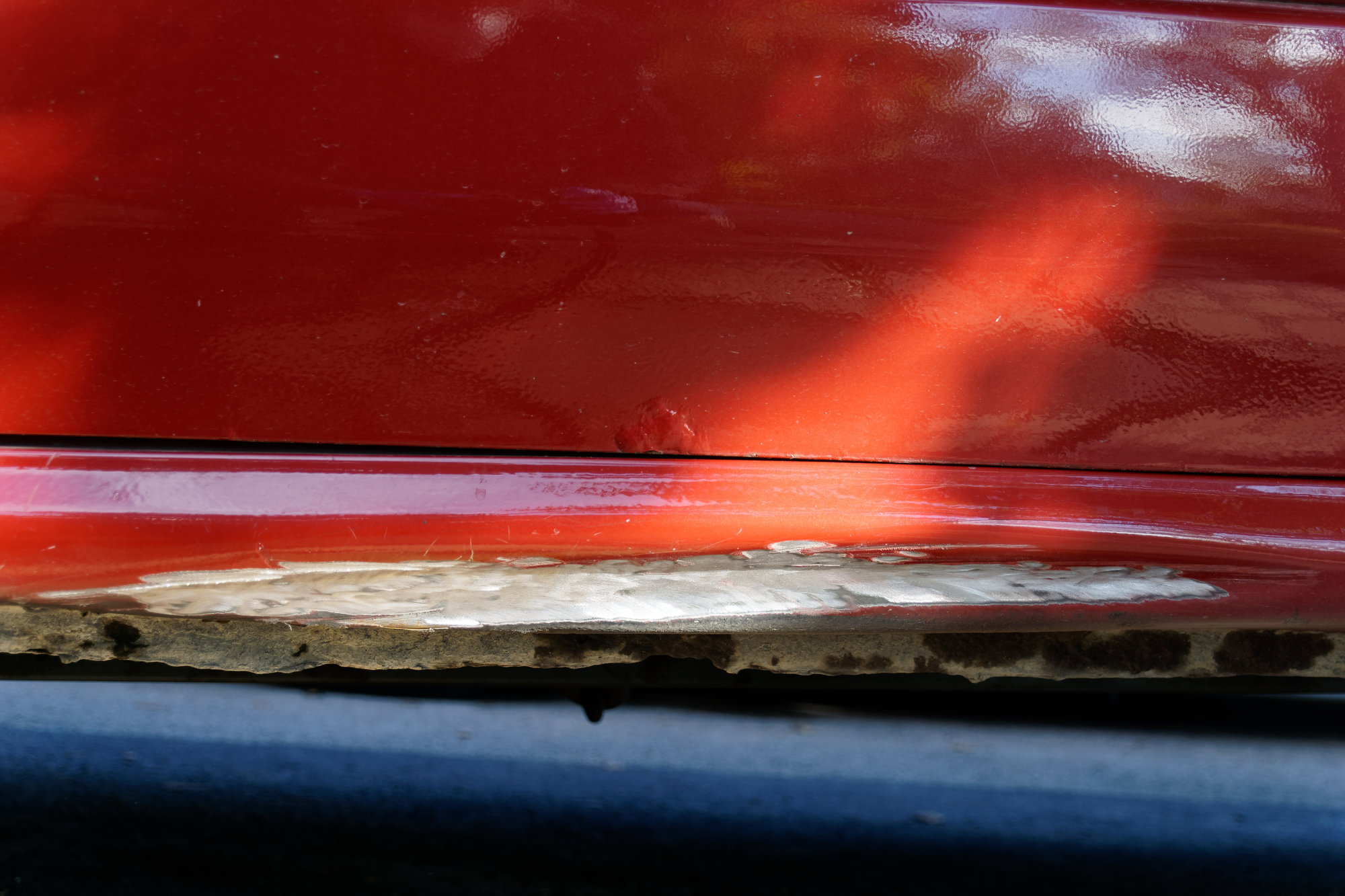
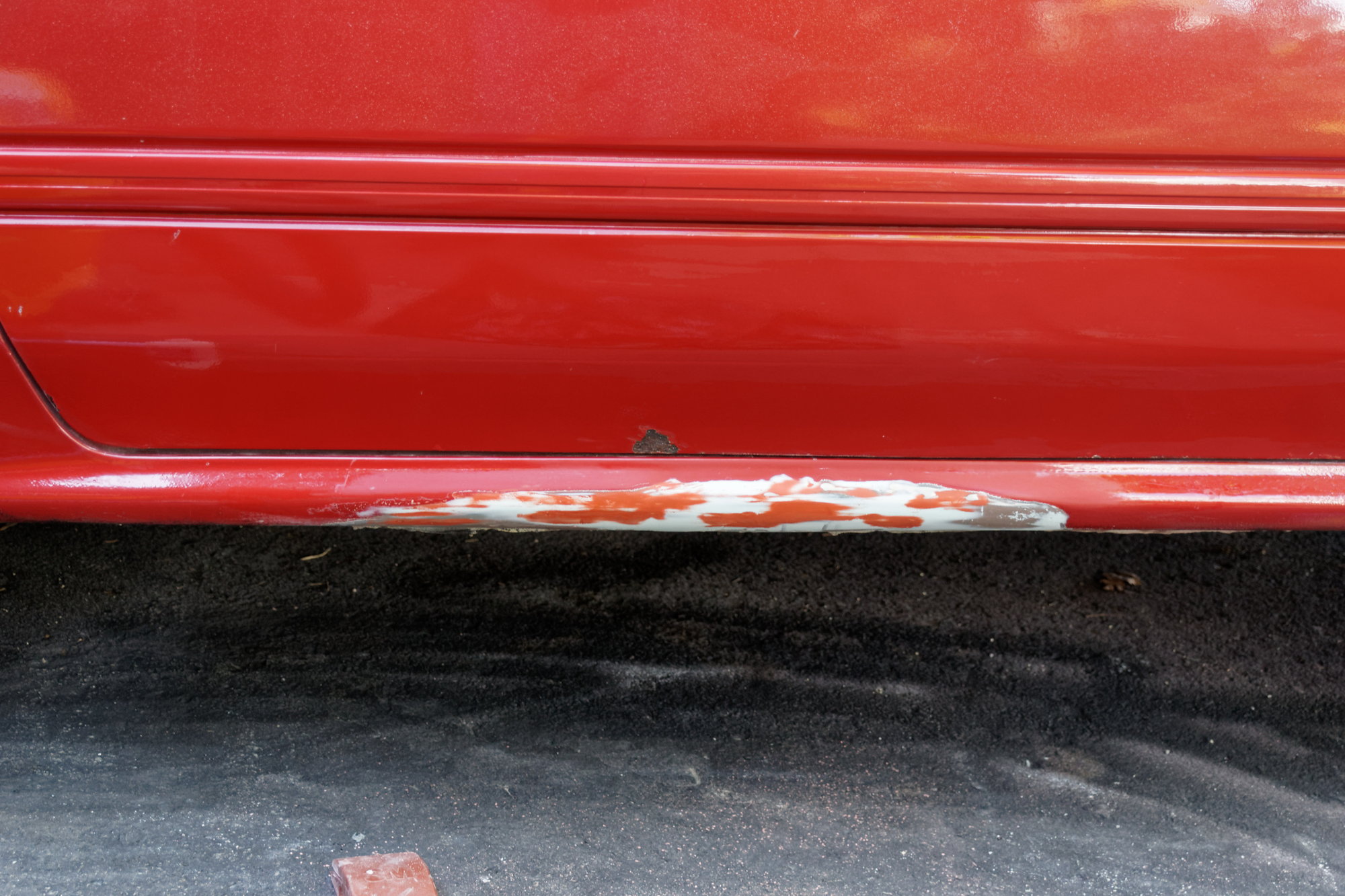
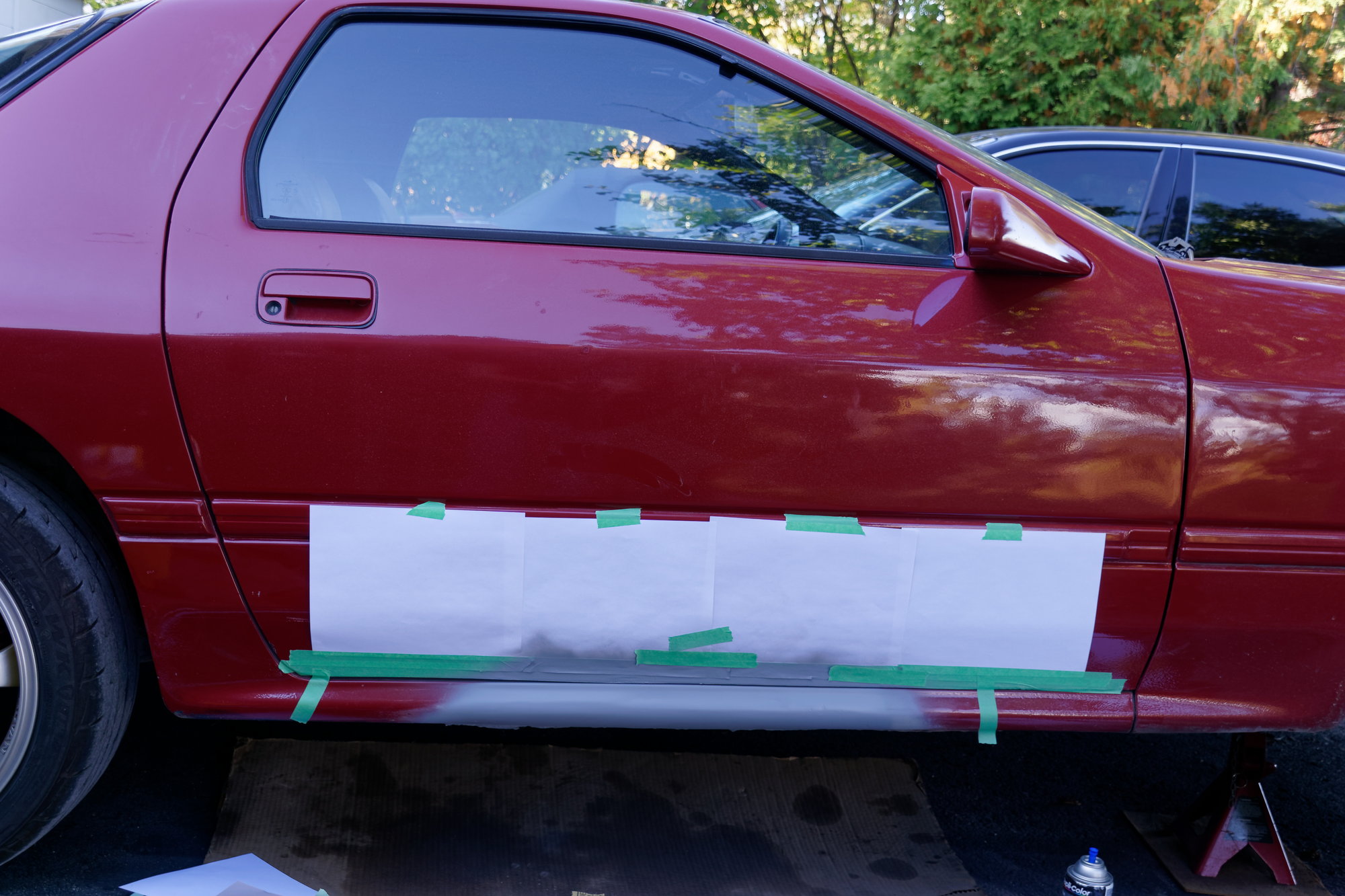
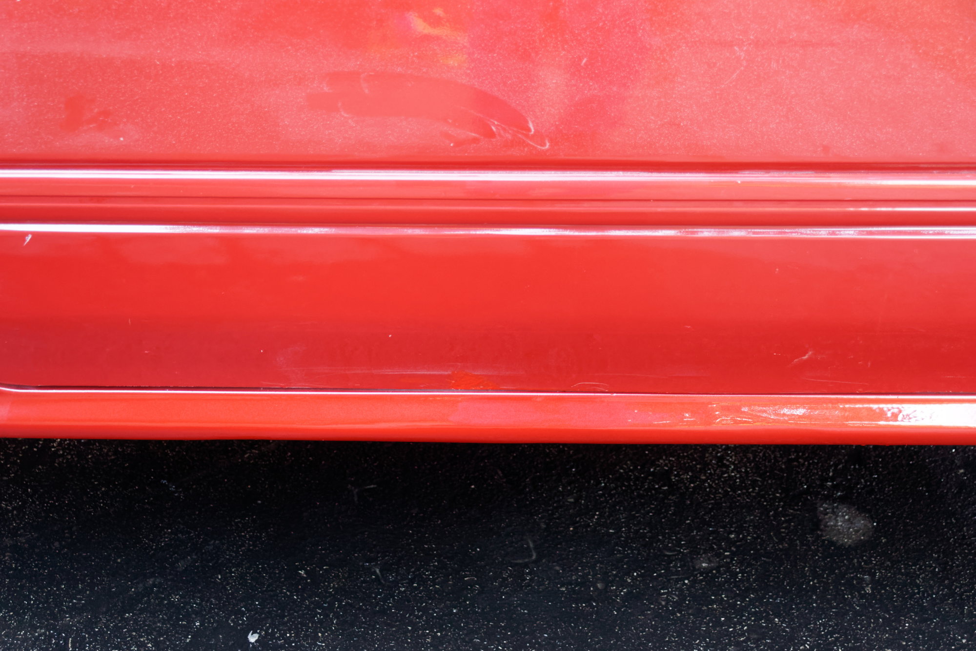
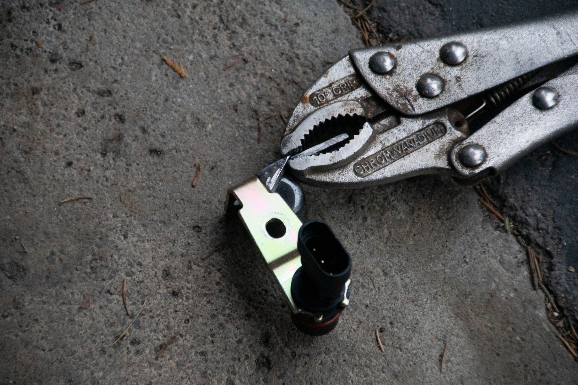
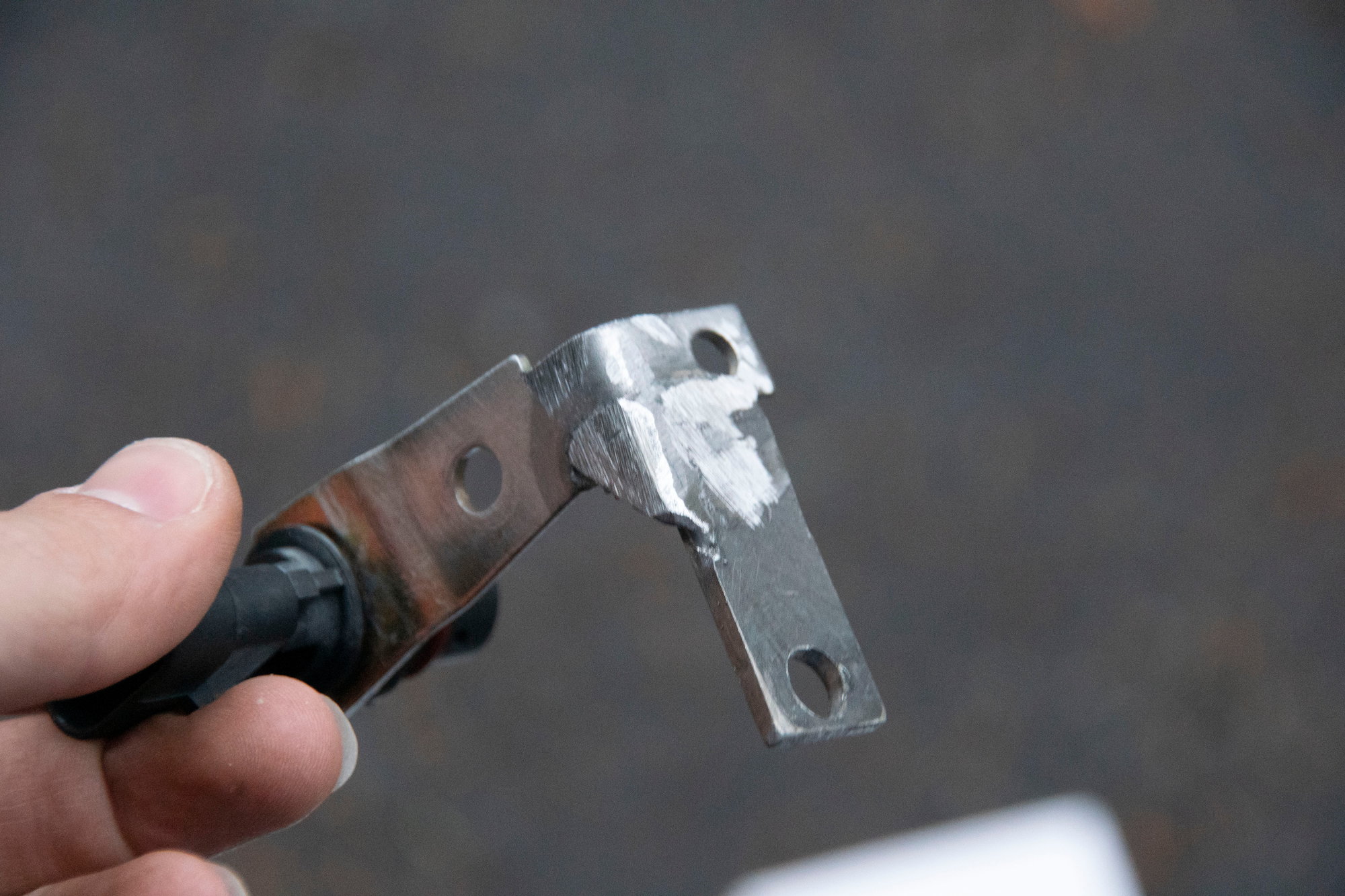
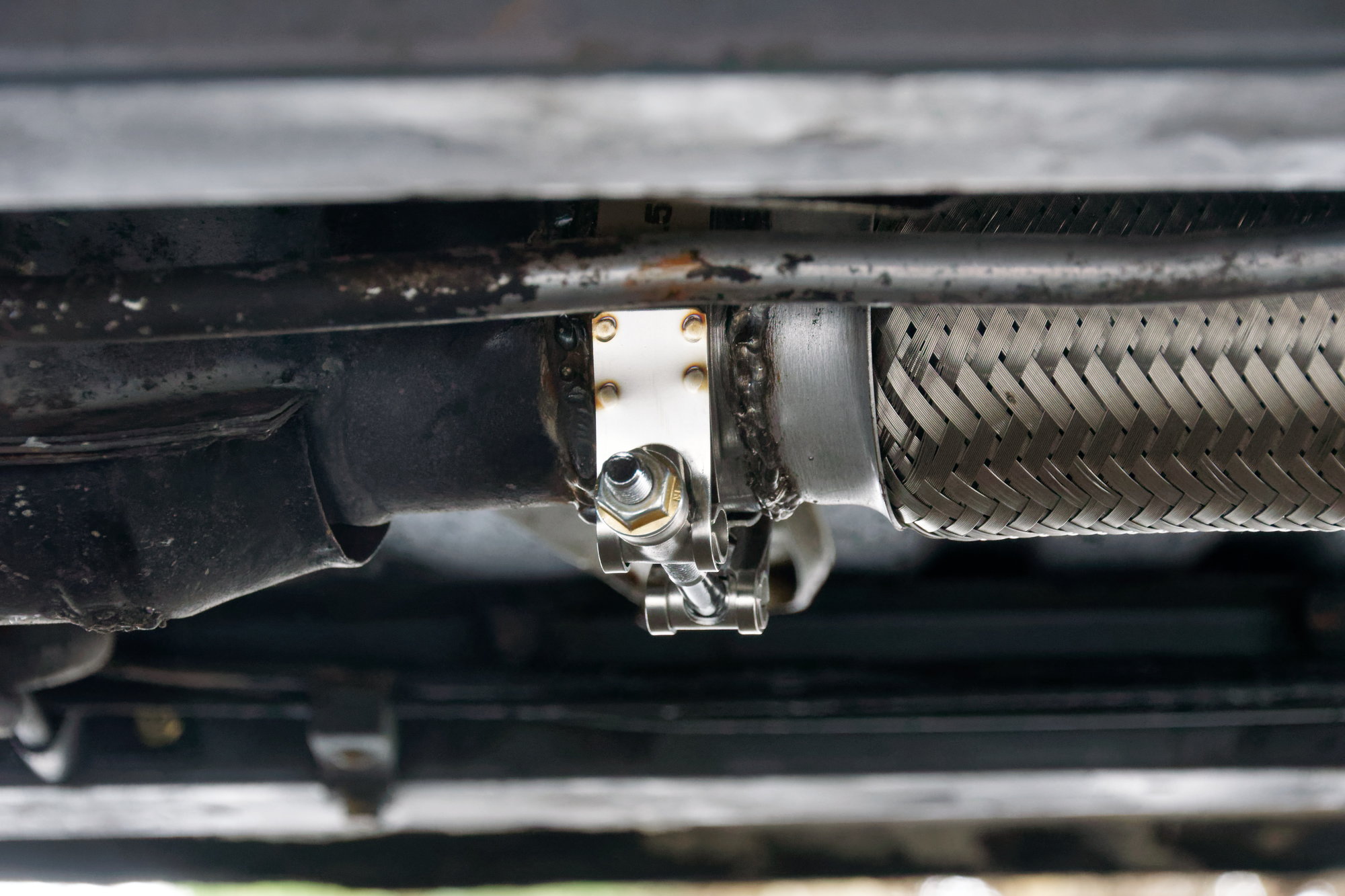
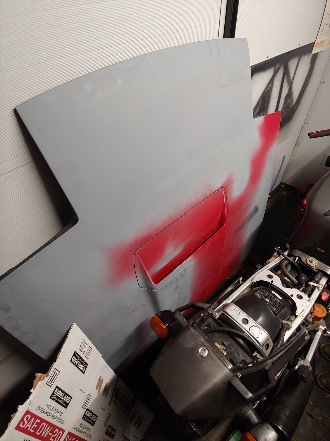
So I'm very happy with the modified CAS. What I'm not happy with however, is my own carelessness:


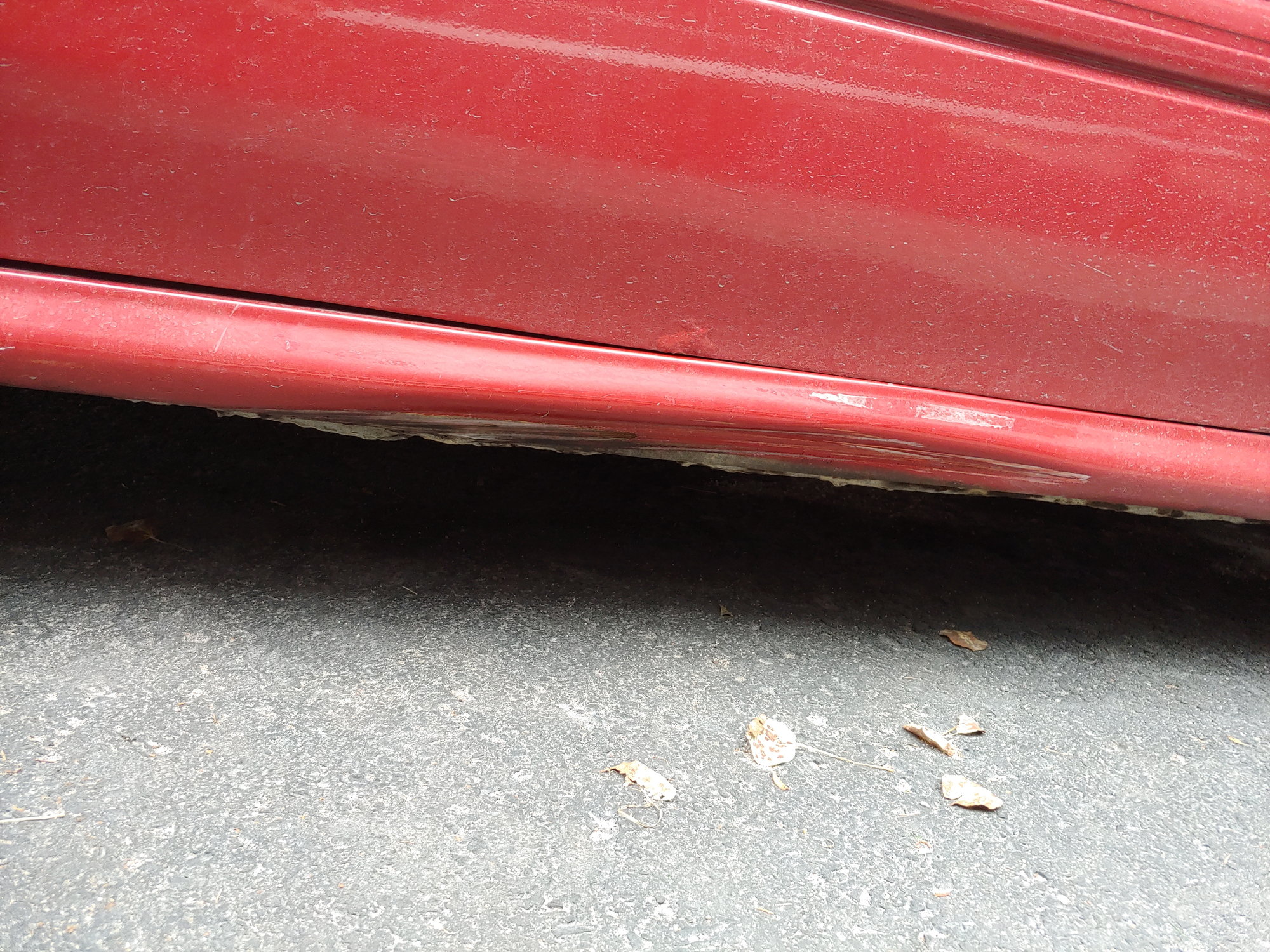
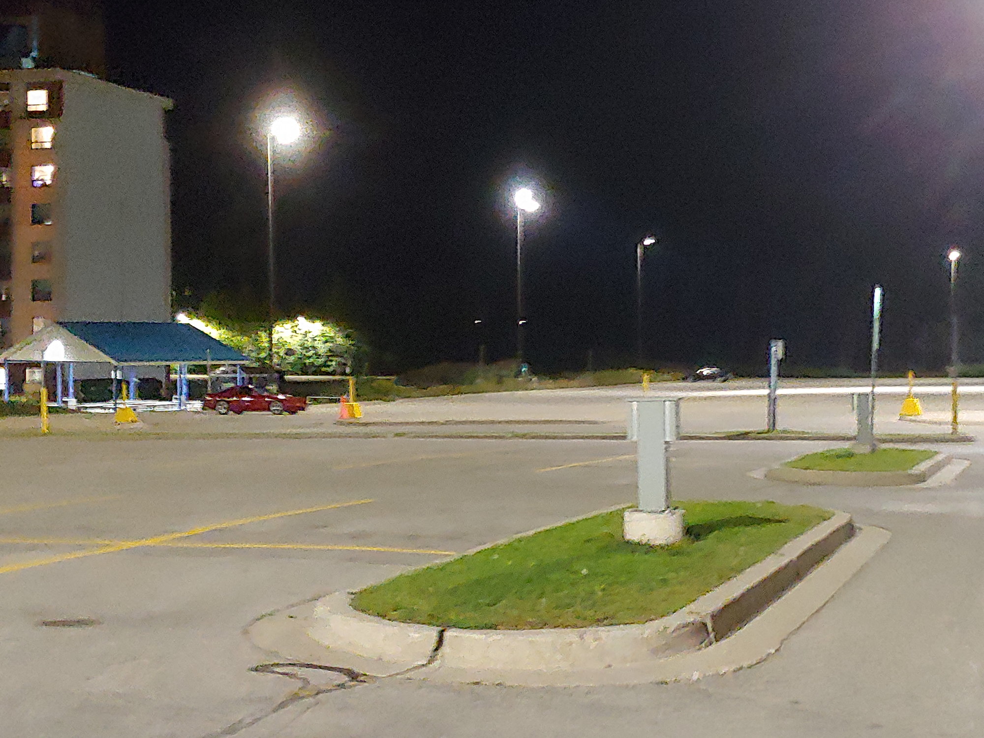
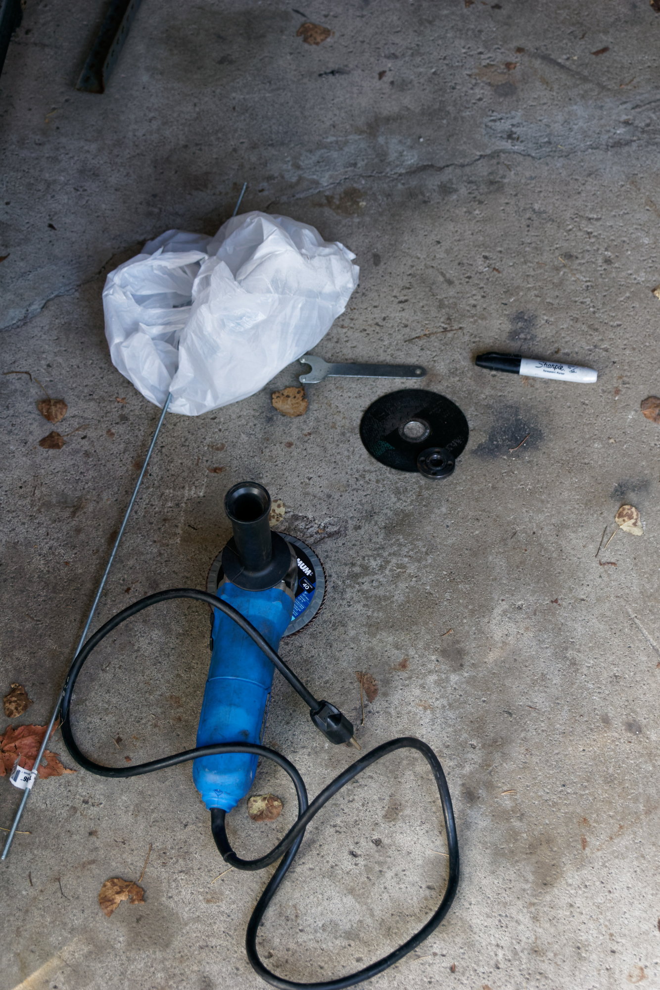
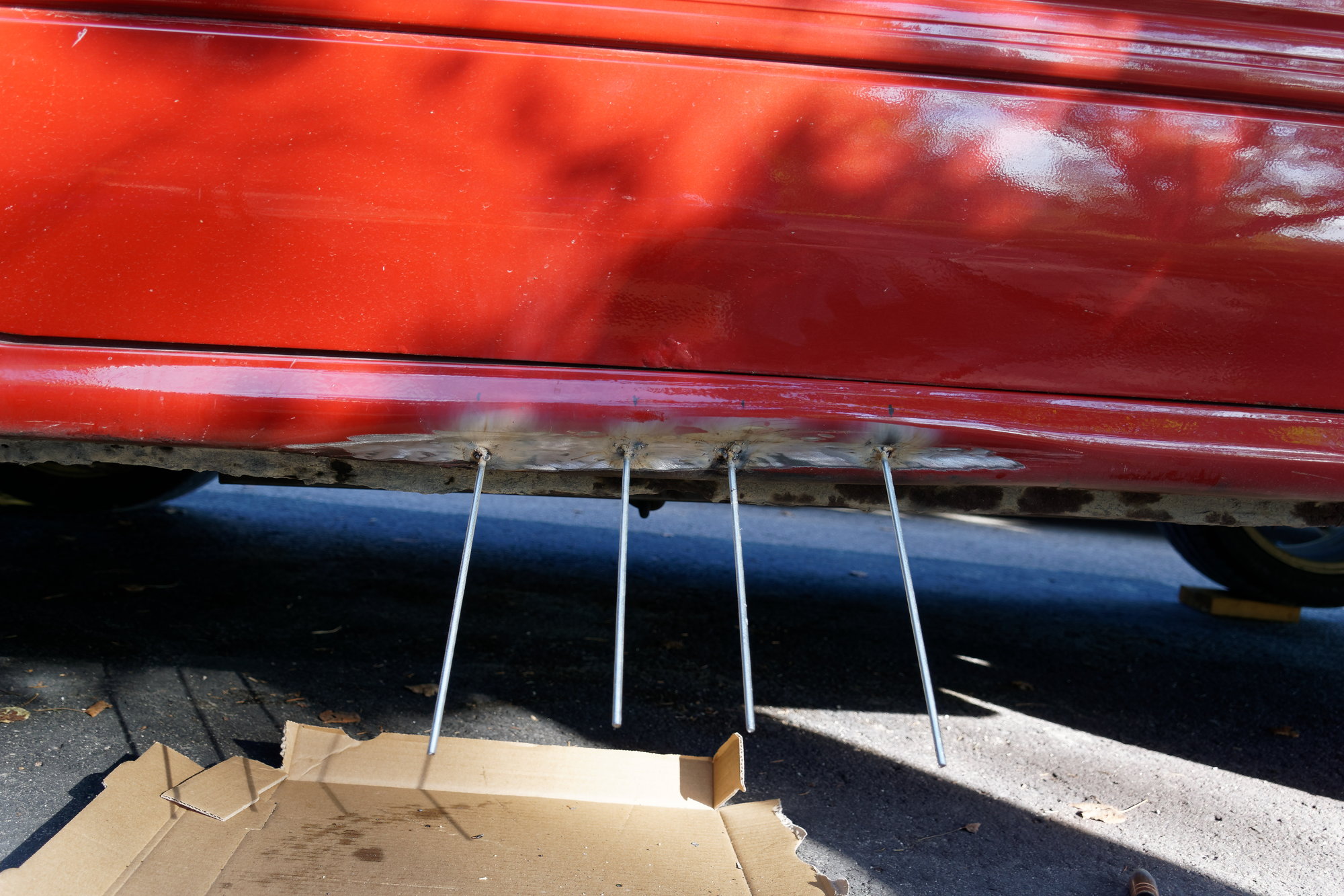
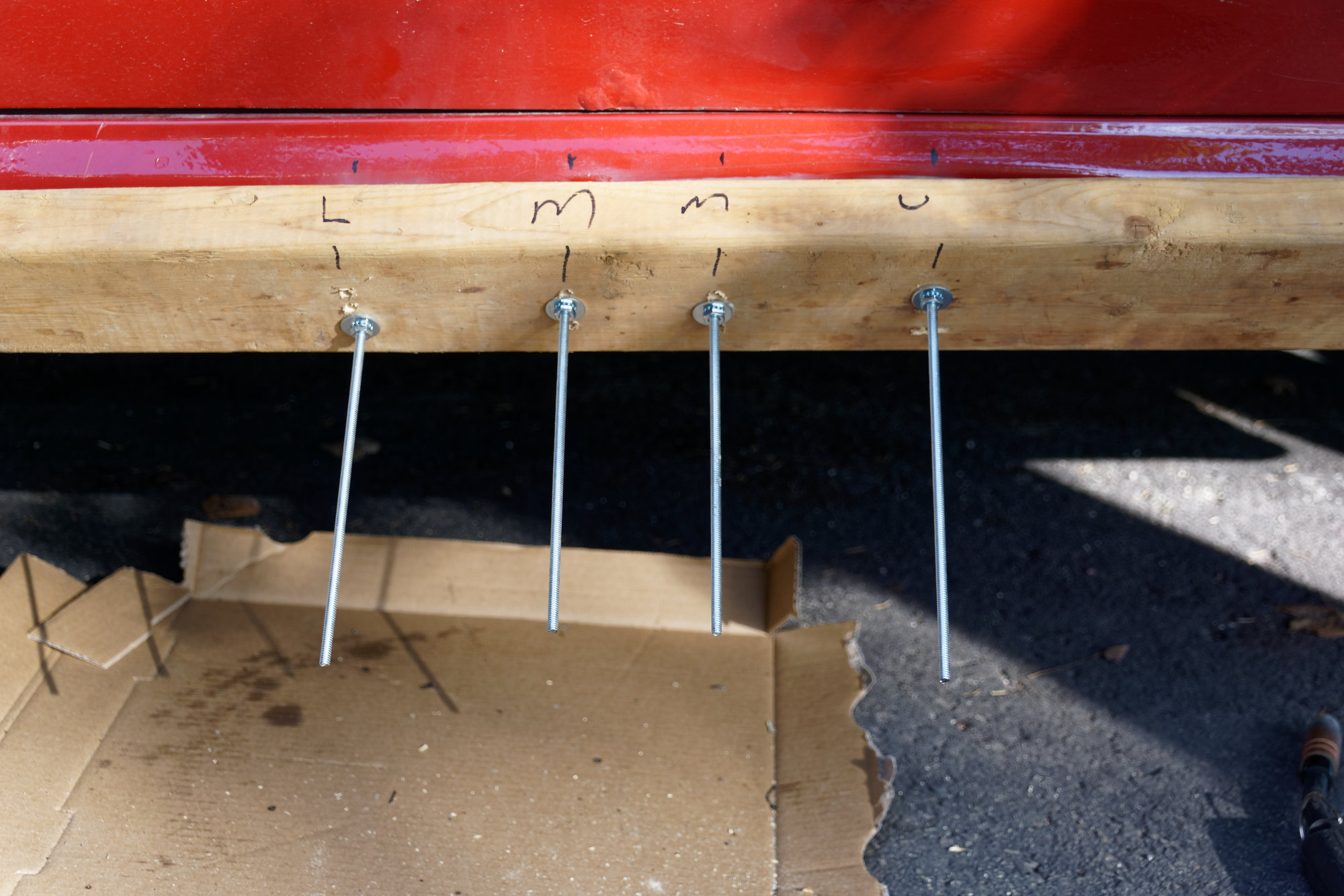
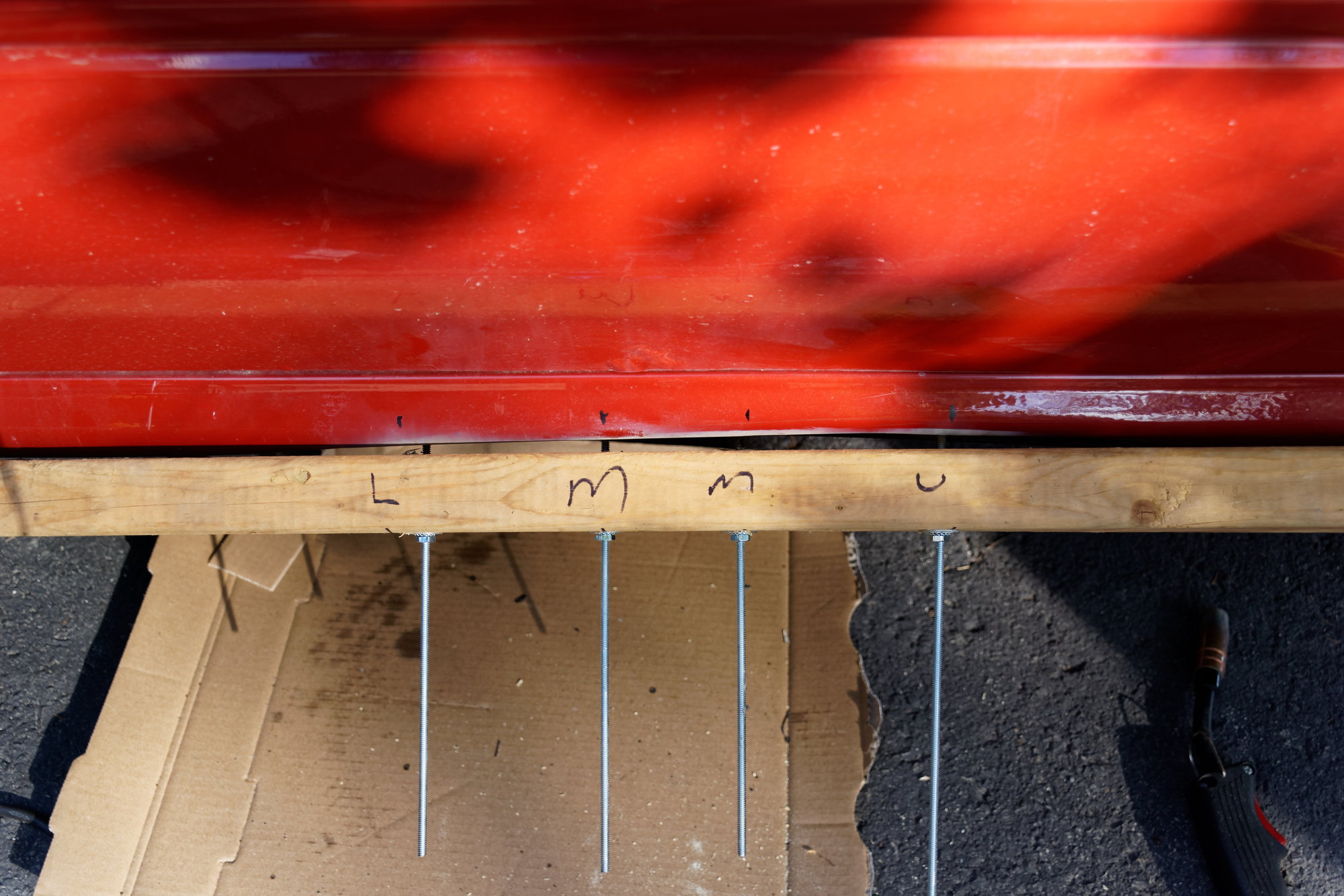
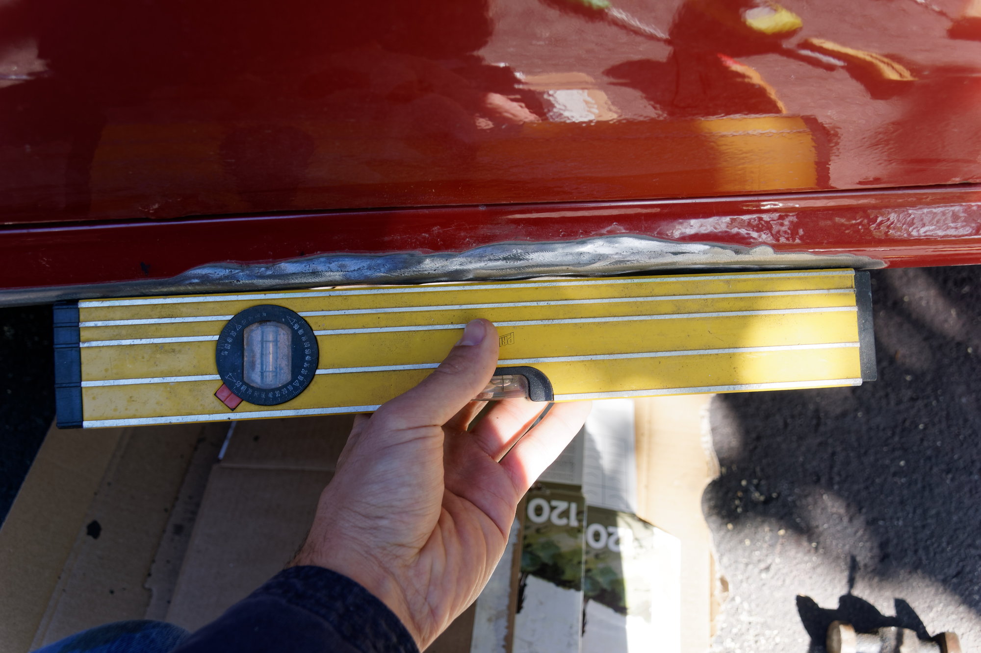
After work on Saturday I went to fill up the tank, and I scraped the curb entering the parking lot. I could go on about how the curb there is unusually tall and it protrudes out a weird angle, but at the end of the day this is my fault. It's fixable, but it still sucks to know that I did that. I can pick up a can of colour match paint from a local shop I know and bang this back into shape using the inner sill for access. I also have a few PDR tools that may help pull that crease back out. I'm going to get it as close as I possibly can, then paint it and call it good. Then add it to the growing list of things that a body shop will need to look at when I get the car painted. Including that bubble on the door.

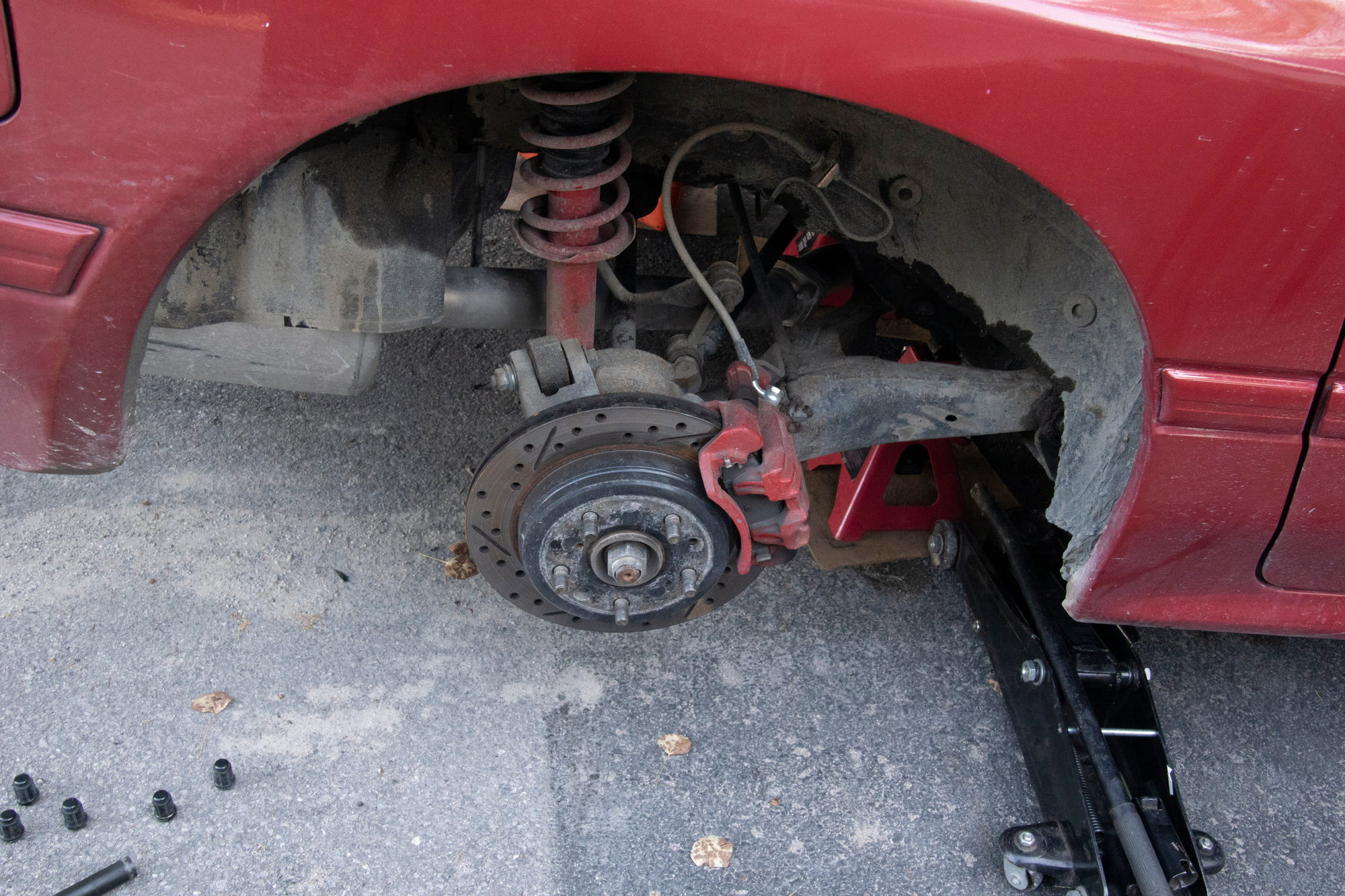
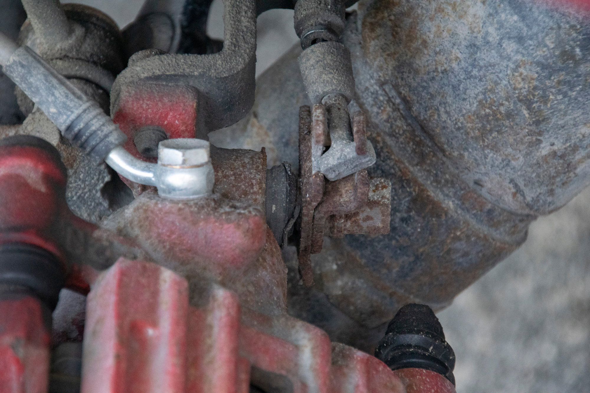
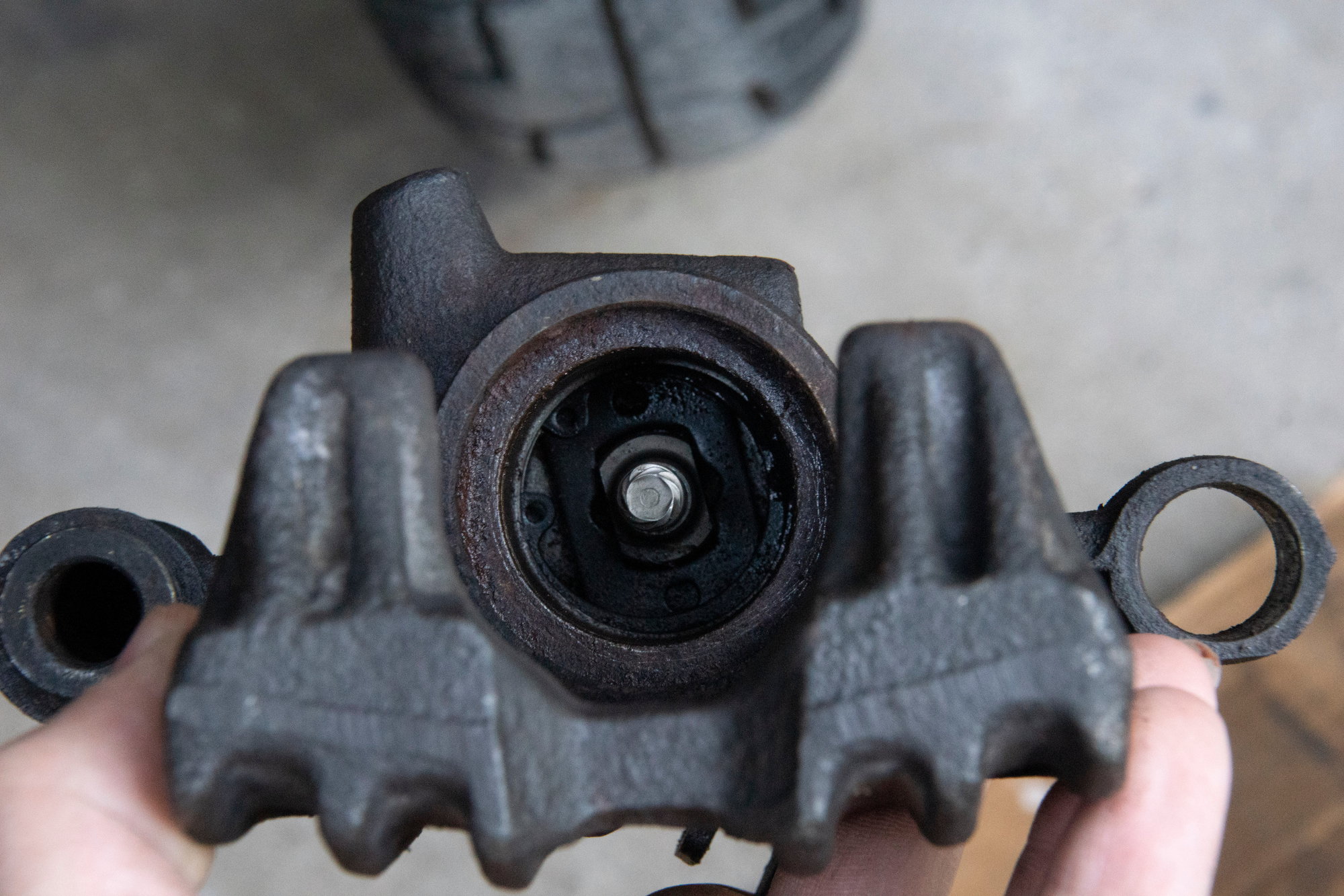
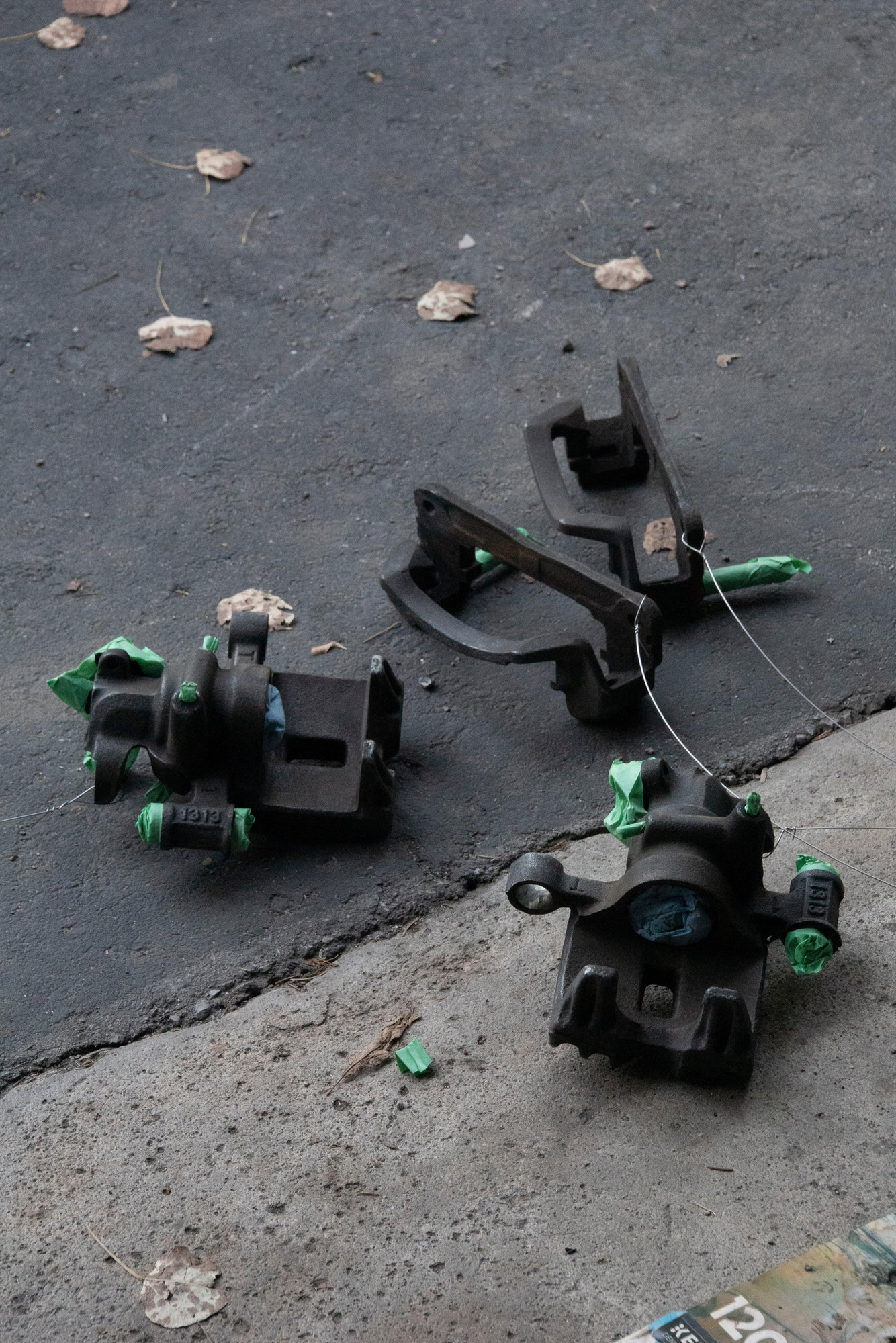
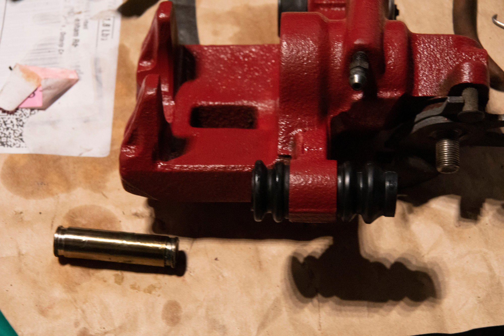
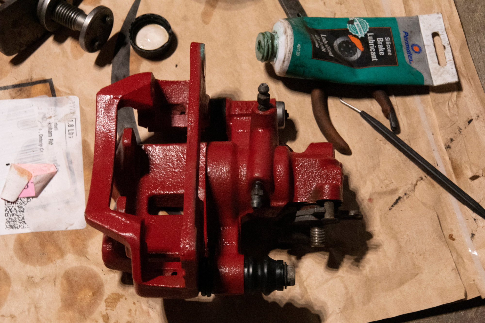
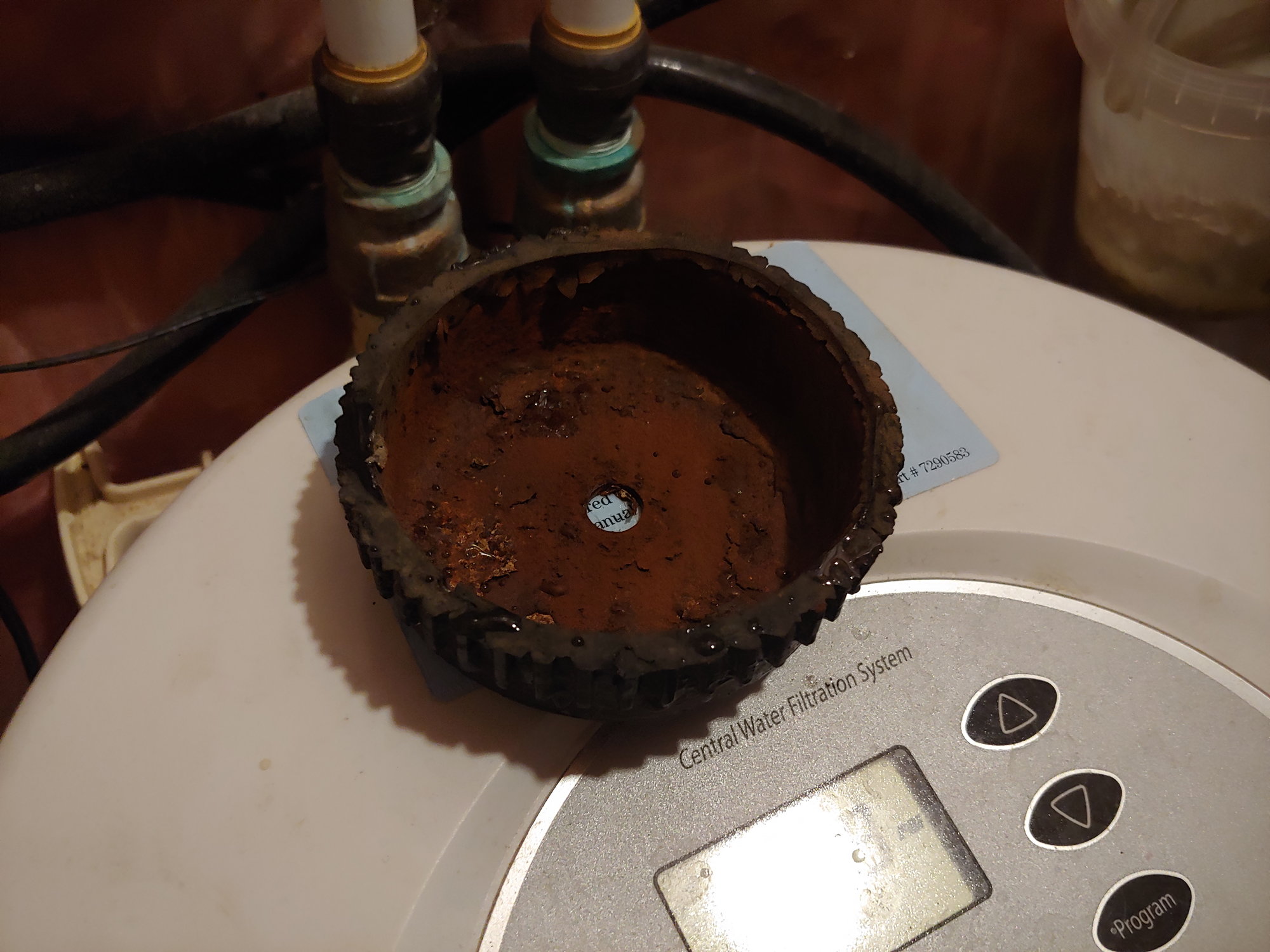
On the drive home from the gas station, I felt a weird drag on the car. Then I heard a thumping noise and smelled Jiffy Pop. That is my cue to know that a brake caliper has seized. Randomly, for no apparent reason, the caliper on the OTHER side of the car decided to seize up. I pulled over and it was immediately apparent due to the heat radiating off the wheel.

On Sunday I drove my Celica to work and back. Wouldn't you believe it, I pull into the driveway and hear a thumping noise and smell Jiffy Pop again. You guessed it, BOTH my cars have seized brake calipers in less than 24 hours.

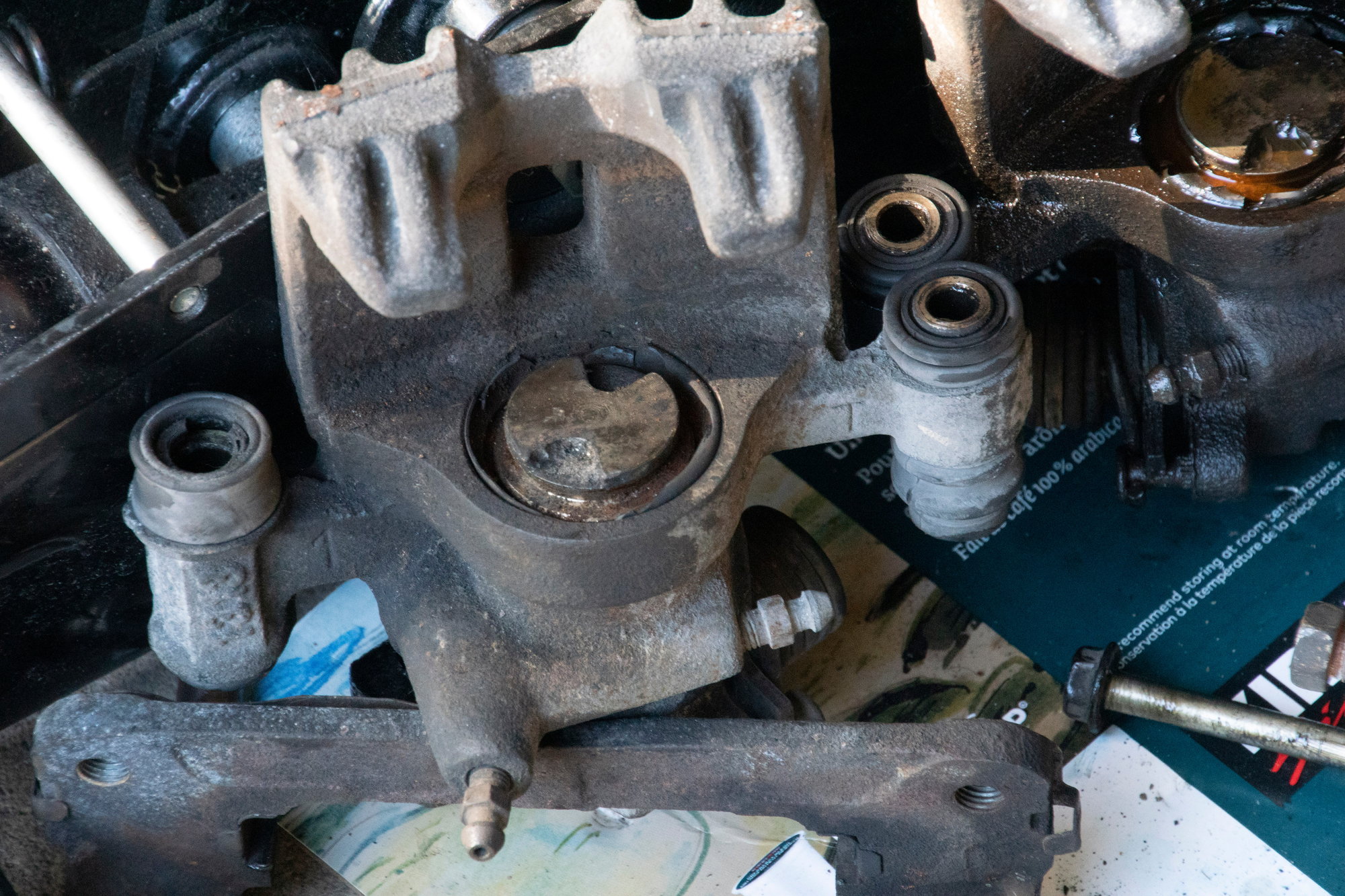
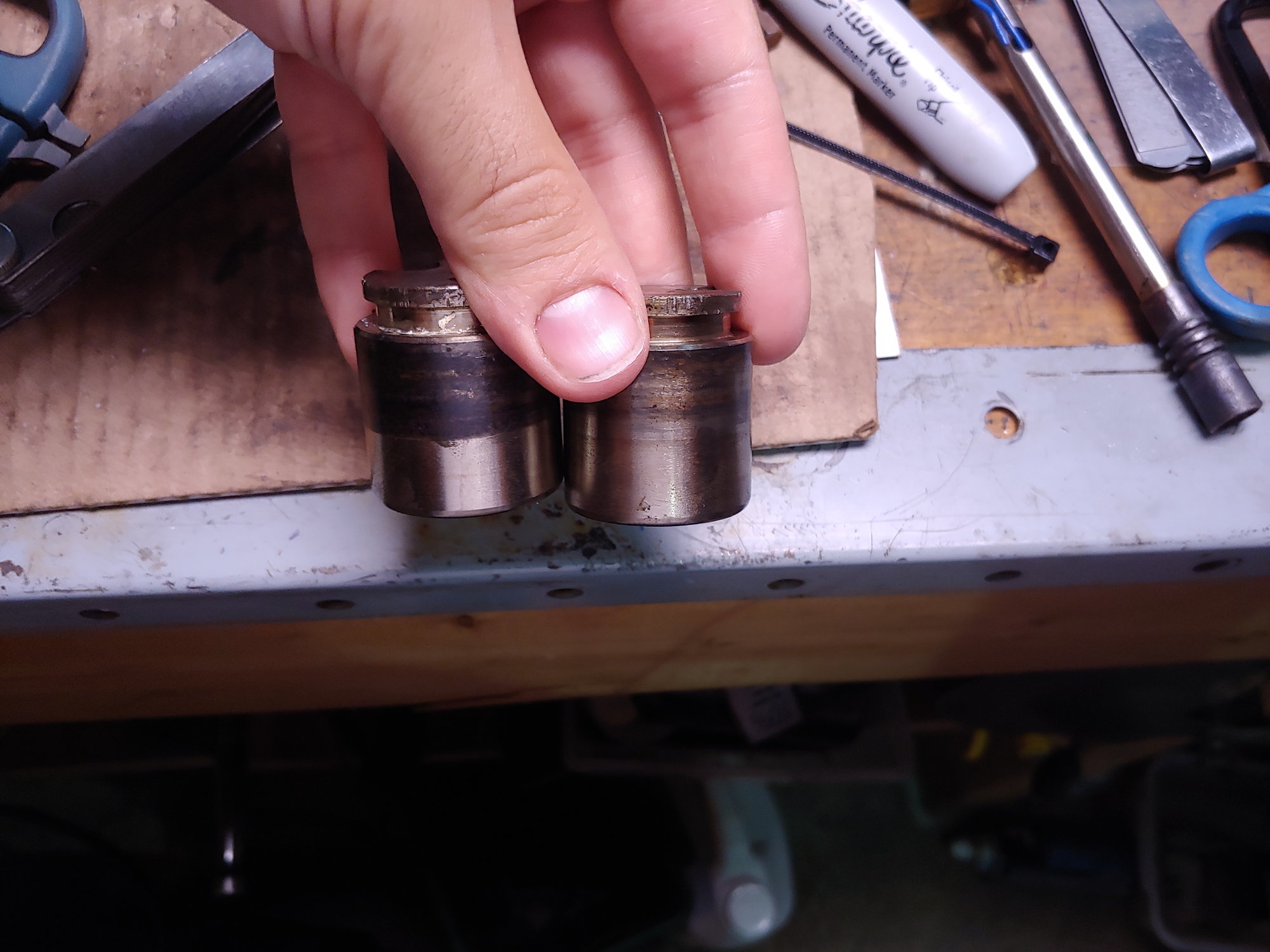
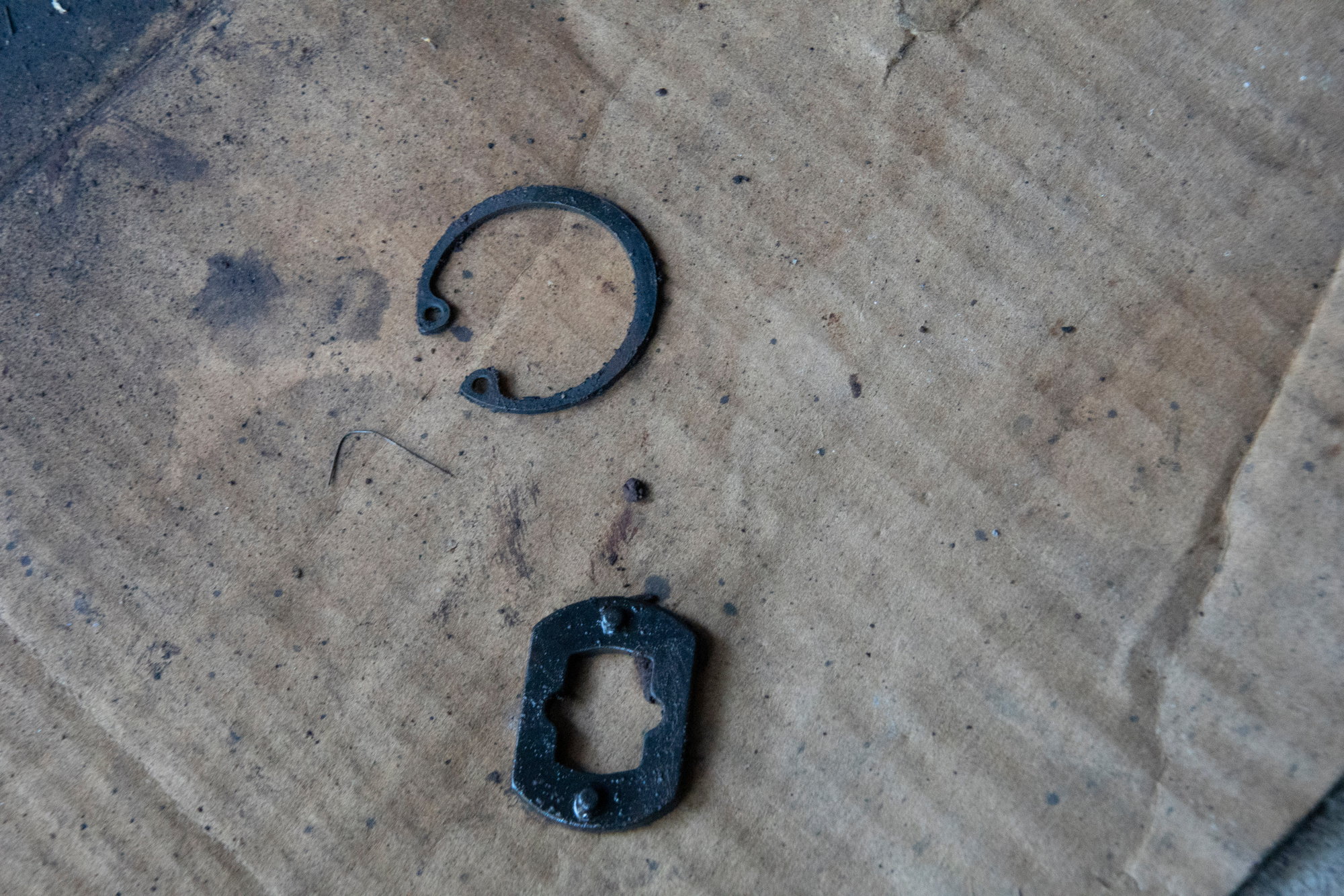
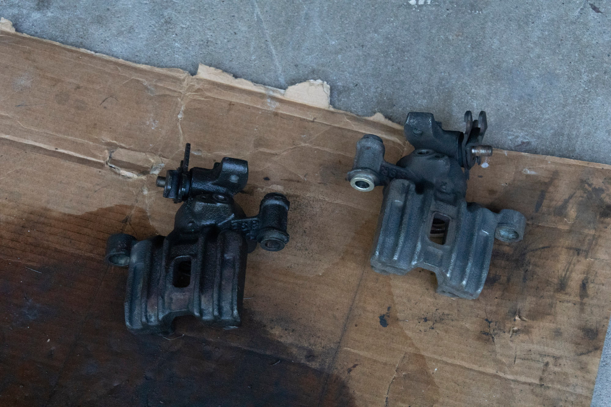
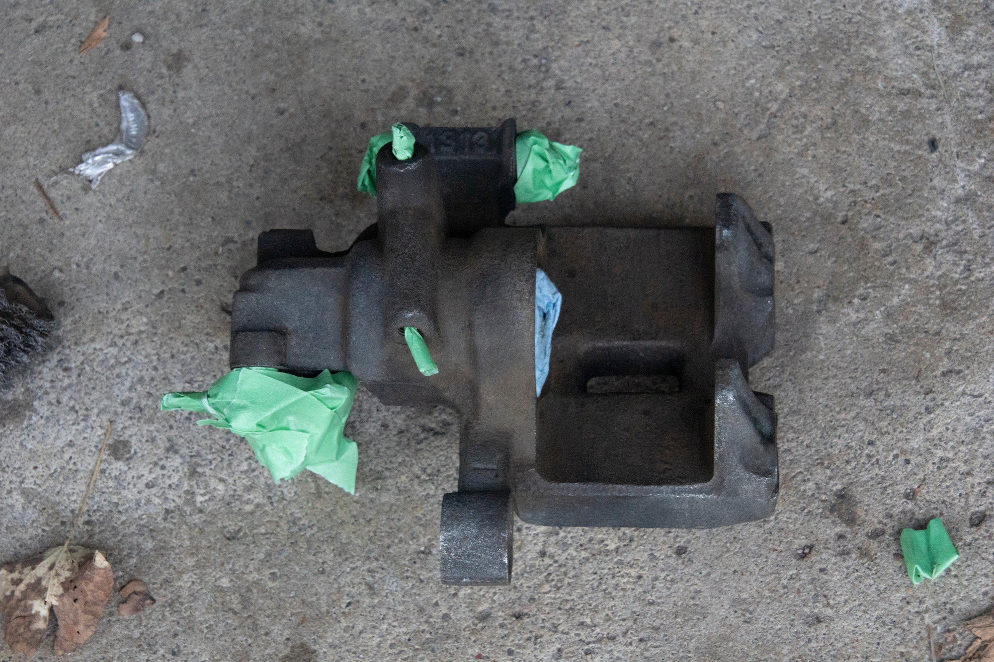
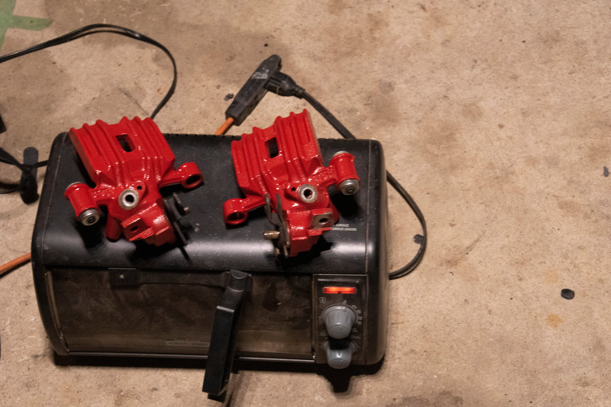
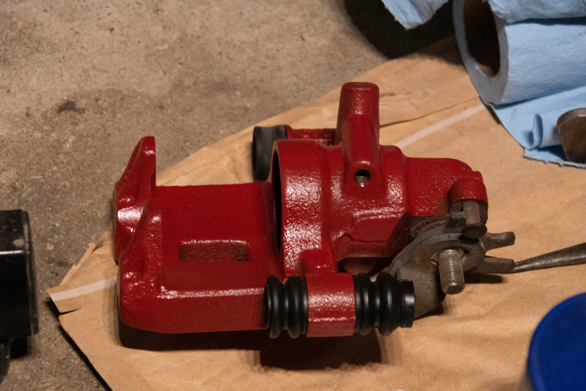
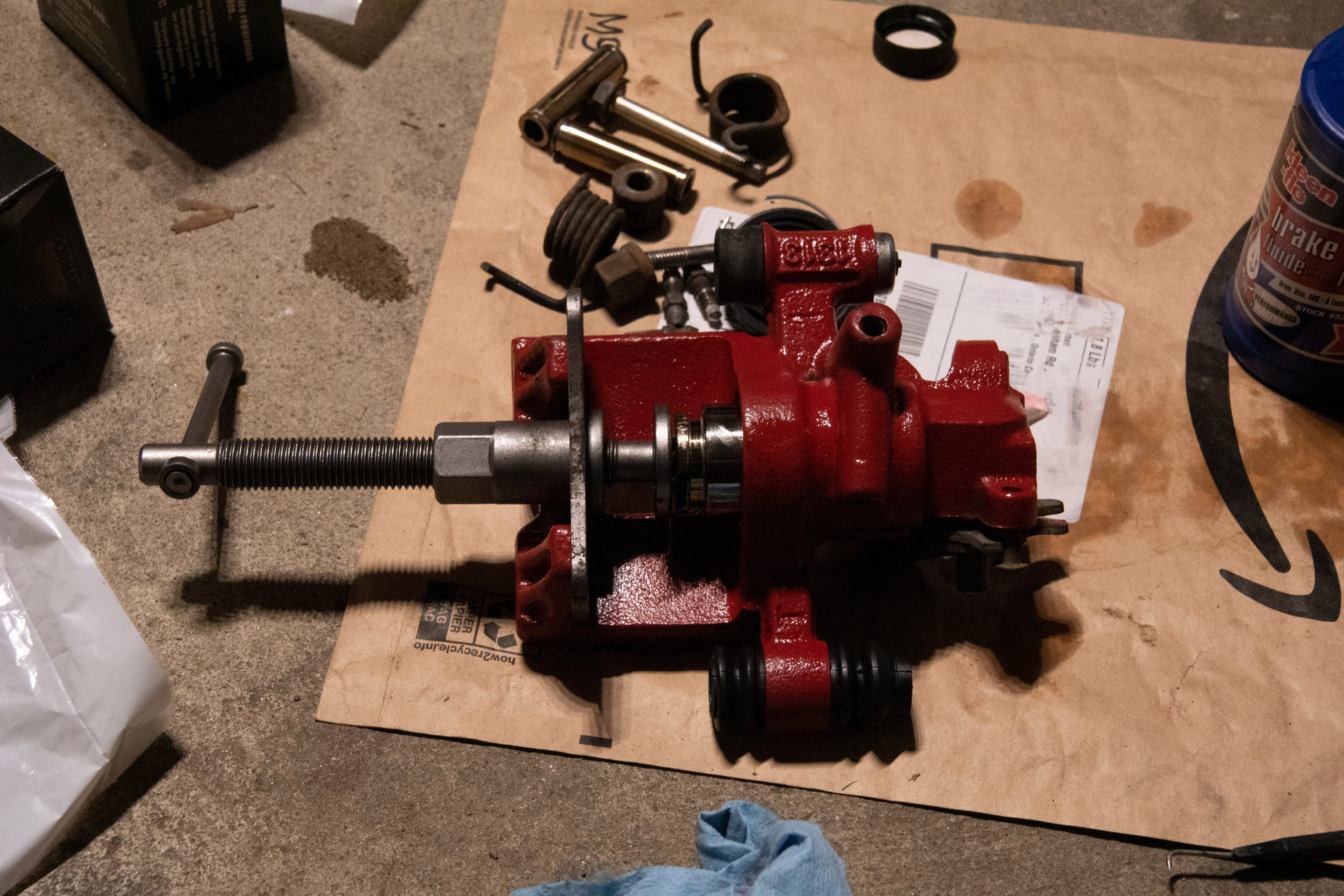
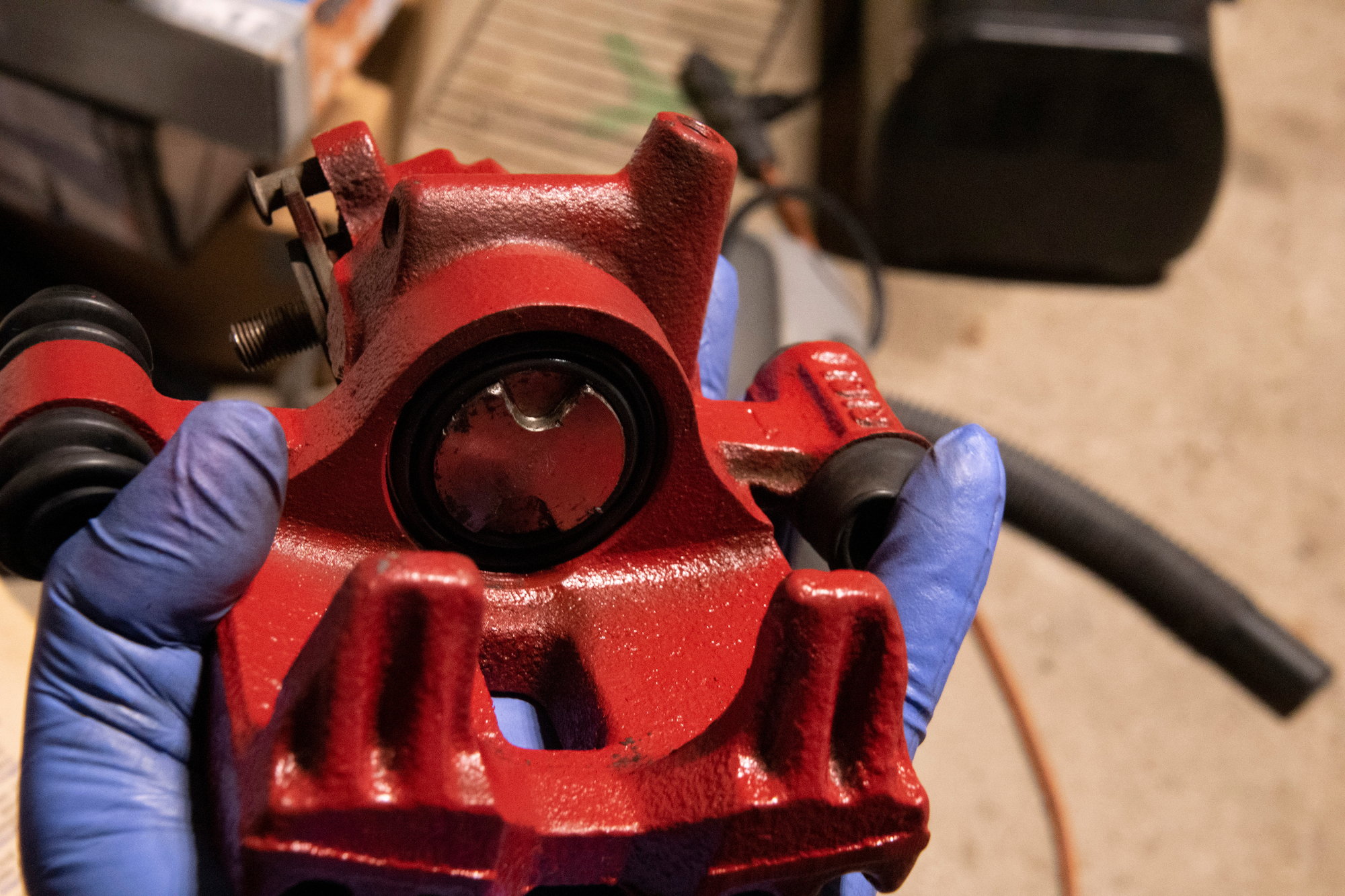
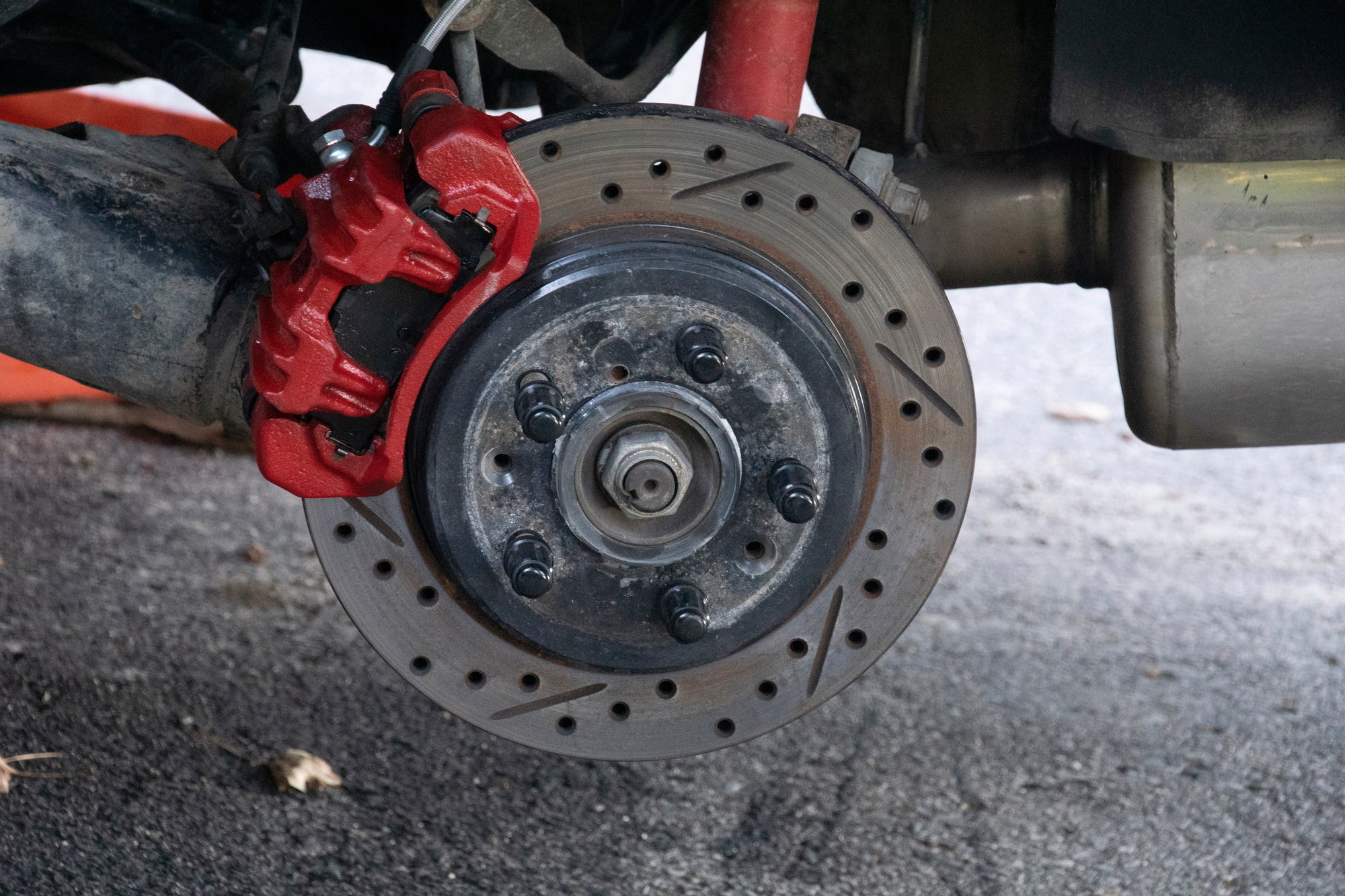
Rear calipers for the Rx7 are tough to find, so luckily I kept that free set I got from the parts yard. I tossed one on and bled it in less than an hour, but it turns out that one is even more seized then my original. So rebuild kits are on order for all the offending calipers.

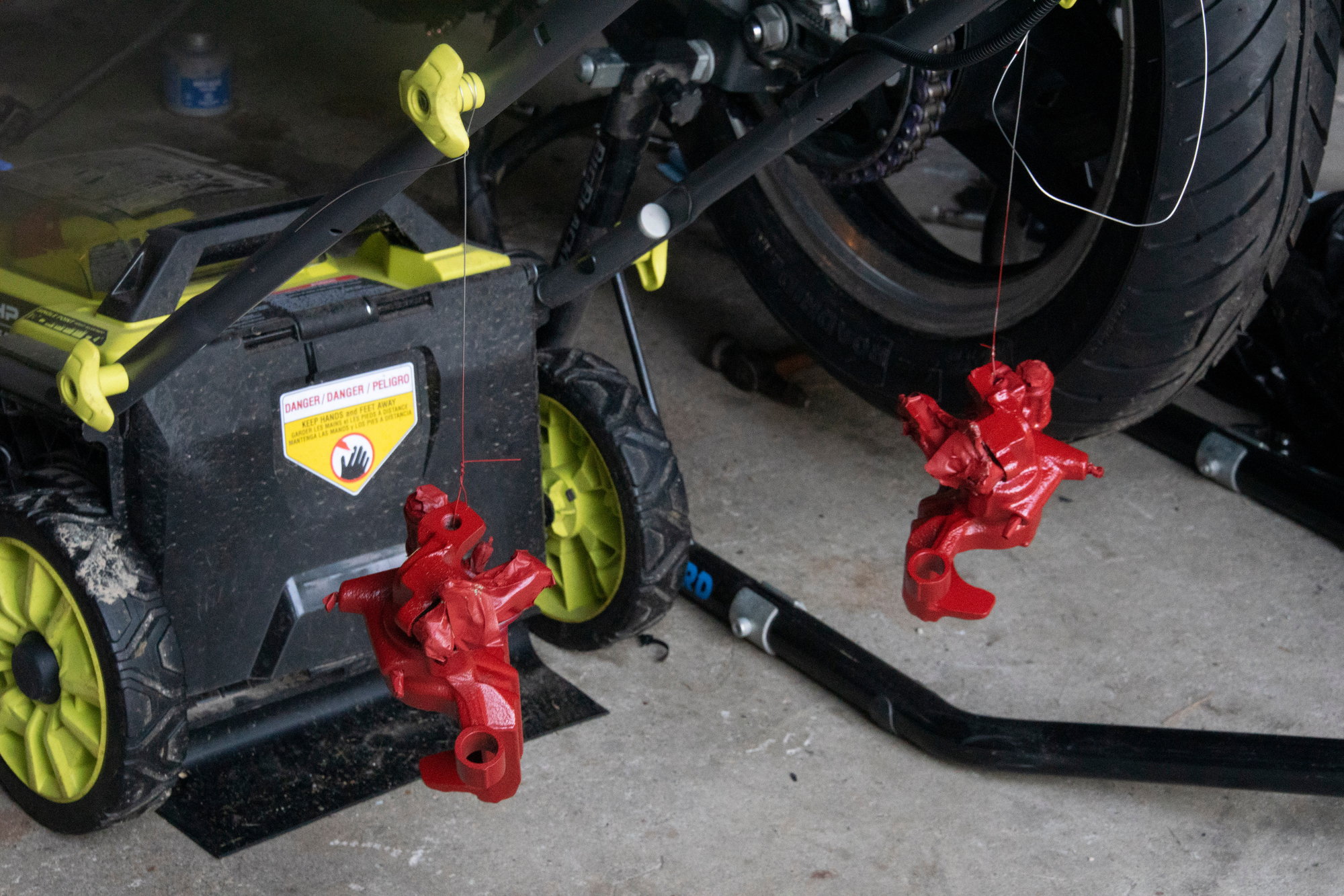
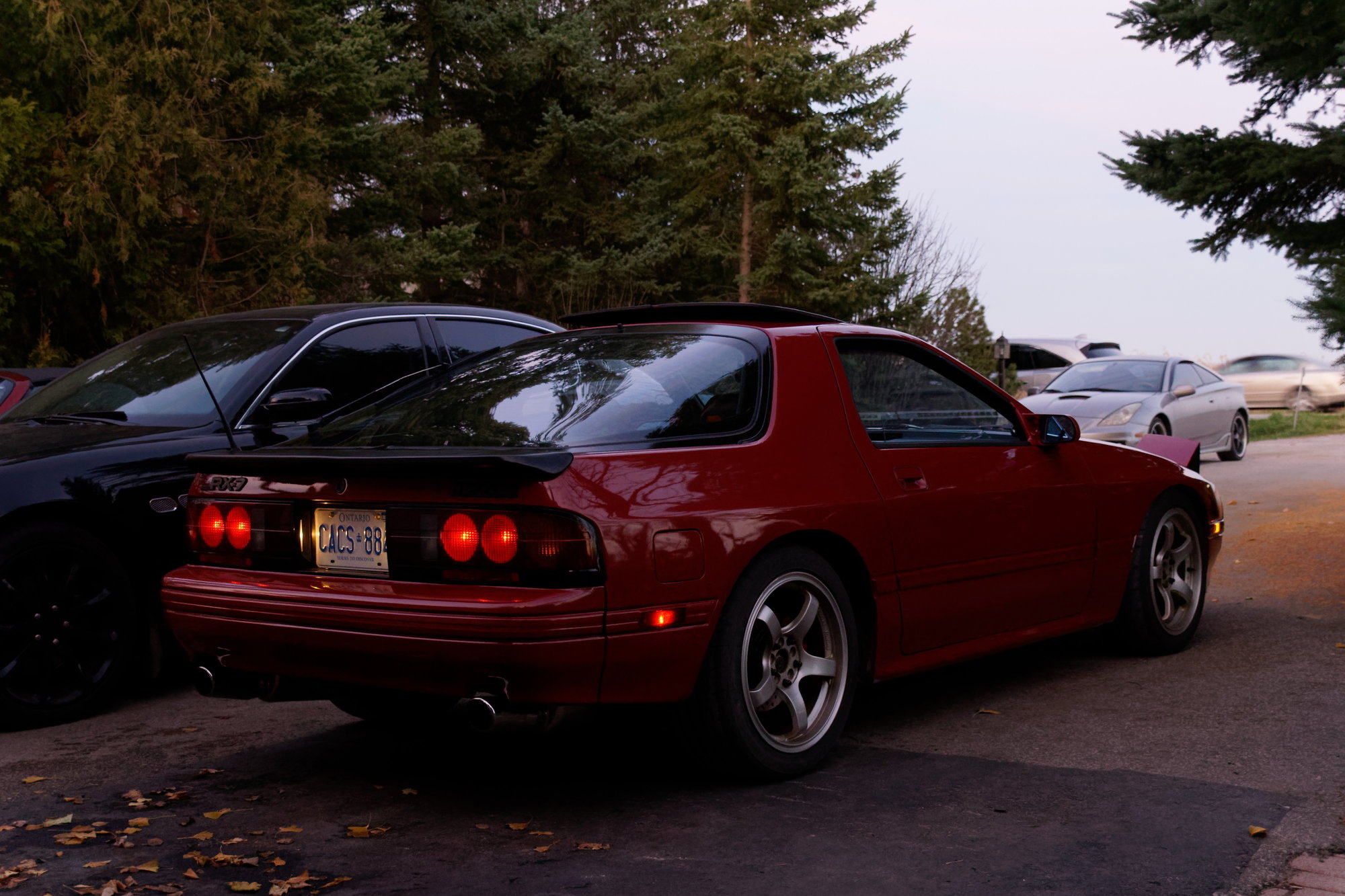
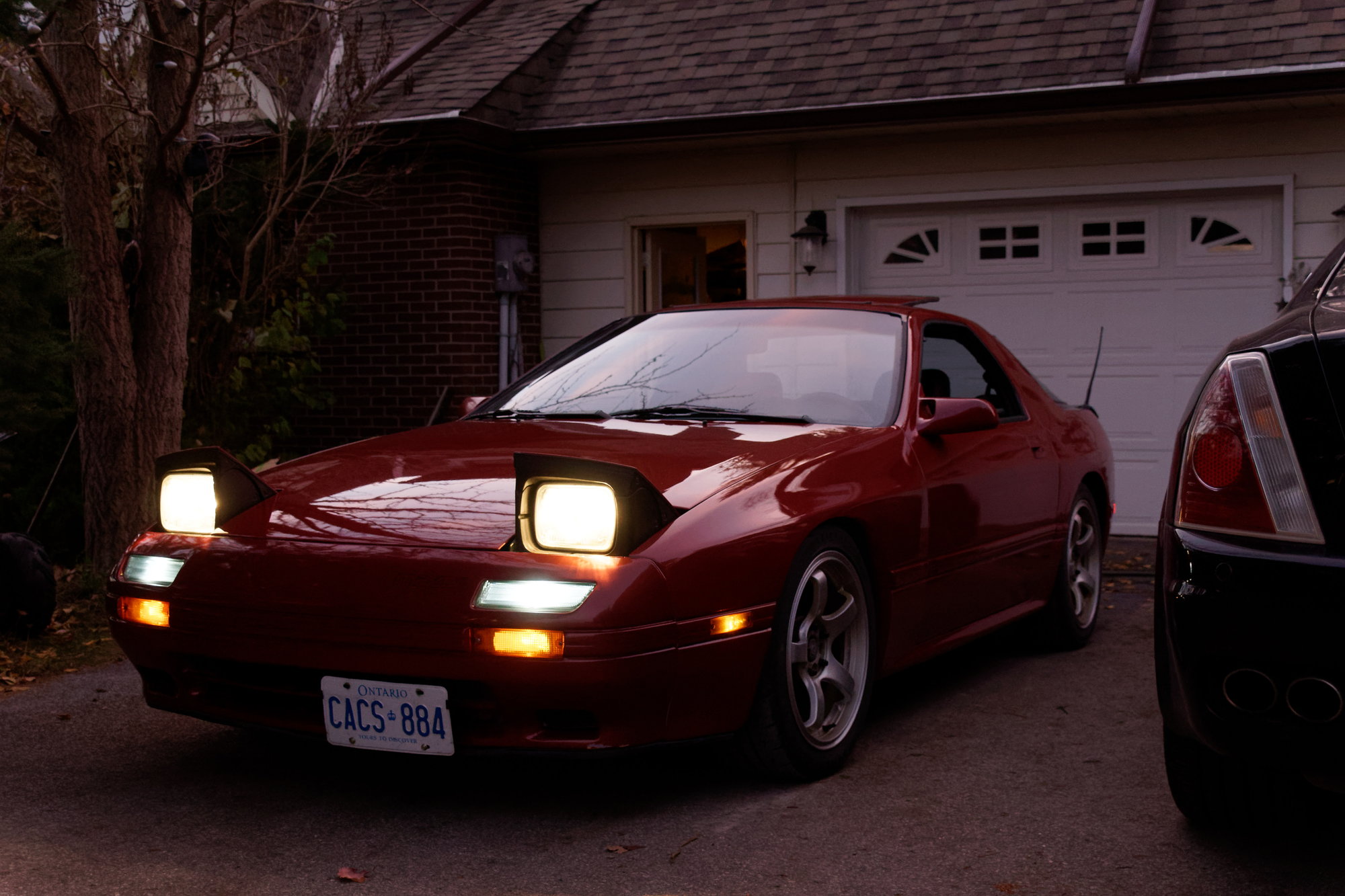
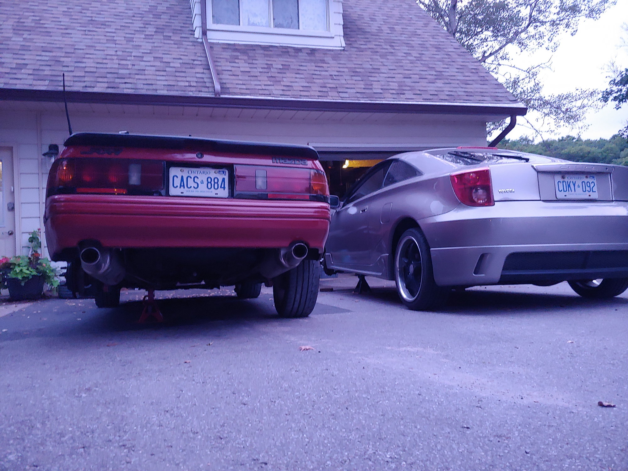
Both cars are back in their natural habitat:


So for now, that's that. I start classes on Wednesday and between work and school I'm looking at 55 hour weeks. I'm going to do the required maintenance so I can continue to enjoy my Rx7, but any major jobs (like the Turbo swap) will be waiting, most likely until spring since I don't have garage access during the winter. The rebuild kits should arrive in a few days and then hopefully I'm good to go.

Until next time :)

WondrousBread
WondrousBread Reader
9/17/22 9:32 p.m.

When I left off, both my cars had a brake caliper seize randomly less than 24 hours apart. On the Celica it turned out a dust boot was not seated properly from the last time I rebuilt the calipers, so just polishing the piston and removing a bit of rust from the end of the bore fixed it. No rebuild kit required, since the rubber was less than a year old and in perfect condition. I made sure to get that dust boot seated properly this time.

The Rx7 needed a bit more care. I ordered a set of rebuild kits, and started by pulling the calipers:


The first thing I noticed is that my rear rotors are on the wrong side. Doesn't hurt anything, but it looks a bit unusual now that I see it.

The second thing I noticed:


The little post that tensions the return spring for the parking brake mechanism is gone. And so is the spring. I never noticed any weirdness and the parking brake wasn't dragging, so maybe that part isn't really necessary? Either way, the rebuilt calipers will have the spring.

I am actually rebuilding the set I got from the yard for free, since they almost certainly have fewer miles than my current calipers (or any of the rusty parts in my garbage bag full of rear caliper cores). Here's where we started:


The boots were intact when I started, but the piston was quite firmly seized in there. So to avoid further damage I let PB Blaster do some of the work for me:


I let that sit for a day or two, and by the time I came back I was able to remove the pistons (with considerable effort). Here's what we have:


No pitting, but certainly not ideal. New ones are available on eBay, but at $150 per piston that isn't an option unless these are 100% unusable. And they're only about 60% unusable, so I decided to polish them up. Results to come later.

Next I removed this little circlip and plate that sit at the bottom of the bore:


They're related to the parking brake mechanism, which I am not disassembling in it's entirety. I wanted to rebuild that as well if possible, but unfortunately there is a needle bearing inside that is not available as a separate part from the caliper. I am sure that I could find a compatible part somehow, but both shafts rotate smoothly so I am going to leave well-enough alone.

Then all the small parts (and a few big ones) took a dip in the ultrasonic bath:


I then spent a few hours with a variety of picks and brushes cleaning the calipers. I ran a tap through all the threads (being very careful not to damage the seats on the bleed screws), scrubbed all the little corners, etc. I spent a particularly long time with a dental pick scraping every bit of rust from the piston seal groove and dust boot groove. So much time in fact that I forgot to take pictures of it.

However, a few cans of brake cleaner later, you can see the difference between the uncleaned and cleaned caliper:


Some places have a bit of surface rust, but I'm not too worried about that. My main concern was removing all the grease and brake dust before painting. The rust only needed to be scrubbed until it was no longer loose. The best thing for cleaning these would be a hot-tank, but with the parking brake parts still installed that isn't an option.

Once all the parts had been scrubbed, it was time to mask them:


To be continued

WondrousBread
WondrousBread Reader
9/17/22 9:32 p.m.

Continued:

My go-to choice for spray paint is VHT Caliper Enamel (and not just for calipers, but for anything). If you clean the surface really well and follow the directions, it's very durable. The first step was cleaning and masking, which is already done. Then I painted the calipers and brackets:


Then I left them to dry around 24 hours before the final step, which is baking. During those 24 hours I had plenty of time to polish those pistons up:


I'm quite happy with them. It took around an hour for the pair, but I was using Meguiar's Scratch-X because I didn't want to be too aggressive. I didn't want to remove any material, so I decided it was best to play it safe.

And it worked very well. You can still see some swirls in the finish, but they are silky smooth. Then I cleaned them thoroughly and put them with the other small parts.


To bake the calipers, I used a little toaster oven I keep around the garage for this exact purpose. I'm not sure what happens if you bake enamel paint in your kitchen oven, but I'm not eager to find out. I put the brackets in first and baked at 200F for one hour according to the instructions on the label:


I ended up leaving them in there around 2 hours to be safe. Meanwhile leaving the calipers themselves on top of the oven got them nice and toasty, ensuring the paint was 100% dry before baking them at full temp.

I only baked the calipers for the specified hour, because there is a rubber bushing on the end of the arm for the parking brake. I'm sure the bushing is heat-resistant since it's on a caliper, but I didn't want to push it. The heat from braking will cure the paint the rest of the way.

After the parts cooled, I put in the new rubber parts:


I used brake fluid to lubricate all the seals and the inner part of the caliper, then rolled the piston seal in. Then I started screwing the piston in with this handy tool:


Make sure to orient the piston correctly, or the pad won't seat:


They went in very smoothly, which was nice since it was such a fight to remove them. Then I lubricated the slide pin bushing with synthetic brake grease and installed it:


Then I lubricated the slide pins themselves, and reassembled the caliper:


And there we go, rebuilt calipers. Well, mostly rebuilt. I would still like to get those parking brake bearings, but it works fine so as long as it doesn't leak I'm not going to worry. I reinstalled them on the car (after swapping the rotors from one side to the other):


And after bleeding the four corners about 7 times with fresh DOT-4, the brakes feel great.

After a few test drives, I took my car for the longest drive I have done since I parked the car five years ago to start restoring it. I drove it to class (around 40 minutes from me) and back. The highway was a bit terrifying, but it gave me a good opportunity to use the auto-tune to dial in the VE table a bit further. I also definitely need to replace the rear diff bushings (the ones I haven't already replaced, I mean) and the rear sub-frame bushings are due for replacement as well. They aren't completely terrible, but they certainly don't help the highway experience. More on the to-do list for the Turbo swap.

I tried to take a picture of my car in the college parking lot, but my phone defaulted to it's useless "night mode", so this is what I got:


What's the point of "night mode" if there's so much noise it's impossible to see anything? Oh well. Either way, driving it was a lot of fun and there was no drama. I'm calling it a success.

Until next time :)

WondrousBread
WondrousBread Reader
9/21/22 9:39 p.m.

This is almost a non-update, but it's kind of neat so I thought I'd share. I recently re-soldered the CPU (again) to try and fix a brake light issue, which turned out to be the switch. A bit of silicone spray on the plunger inside the switch has fixed the issue nicely.

Anyways, tonight I went out to get something from my Rx7 and noticed this:


My factory option back-lit keyhole started working. I spent some time on that last year installing an LED bulb when I had the handle out for unrelated reasons, and was a bit bummed that I put it all back together and the back-light never came on. I guess the CPU cold-solder joints strike again.

At some point I am going to put all the bulbs back in the warning lights and see if it fixed that too. I got tired of the seat-belt light (and others) blinking in and out for no reason, but maybe now they work.

WondrousBread
WondrousBread Reader
10/4/22 6:43 p.m.

I hate bodywork.


I hate bodywork...


I. Hate. Bodywork.


I HATE bodywork.


I hate bodywork.

adam525i
adam525i GRM+ Memberand Dork
10/4/22 9:43 p.m.

You might hate doing it but the results look like it was worth it

WondrousBread
WondrousBread Reader
10/4/22 10:44 p.m.
adam525i said:

You might hate doing it but the results look like it was worth it

I don't know why I dislike bodywork so much. But the hard work today was the penance that I had to pay for being careless enough to put that dent there in the first place.

Overall I'm happy with how it turned out. Turned my car from a 20 footer back into a 10 footer :)

WondrousBread
WondrousBread Reader
11/10/22 8:16 p.m.

It's been a month since I posted, and not a lot has happened on the Rx7 front. Despite the sync-loss issue returning, it continues to run perfectly fine and be fun to drive. A hall wheel conversion is in the works.

Here's a couple pictures I took this evening after driving back from class:


I have a few irons in the fire, and hopefully I'll have at least one wrapped-up in a few weeks that I can post about.

Oh, and if you're a fan of long, drawn out, elaborate solutions to problems that most people don't care about, I have a big one for you soon.

Until next time :)

WondrousBread
WondrousBread Reader
12/5/22 6:07 p.m.

When we left off I discussed a hall wheel conversion that would let me retain the PS and AC. Well, the parts arrived today. And while I probably should have spent the time on something else, it was still above zero here so I decided to make hay while the sun was shining (figuratively - there was no sun). The photos will get grainier as the light disappears and the camera ISO gets cranked up, so apologies in advance.

Starting out, I got this custom 36-1 wheel from an eBay seller called Elenel. The price was fair and the quality is great.


These are the dimensions:

ID 113mm
OD 153mm
Thickness 4mm

These dimensions need to be fairly exact, although 112mm ID would probably be better for reasons I'll explain later.

The sensor is a simple late 90s GM sensor. I believe it's an S10, although it's probably used on multiple cars (hence why it's available for less than $30):


Then I thought for awhile about the location of the sensor. The location that Full Function Engineering uses with their kit is good, but mounting it is a challenge (which is part of the impetus for this entire project), so it's basically out. There are no practical mounting locations near the bottom of the engine, so mounting it underneath is not an option either. This leaves two possibilities:

- Mount using a custom bracket and the bottom alternator adjuster bracket bolt

- Mount using the air-pump adjuster bracket hole.

Mounting from above would be my preferred option since it keeps the sensor as far as possible from rain and dirt, but unfortunately it gets very close to the belts. I have also misplaced my AC compressor bolts (the really long ones) which means any mount I made may need to be altered once the AC goes back in. For those reasons I chose the air pump location instead.

My air pump is "remote mounted", so this makes it easy:


It may work with the air pump in the stock location, but otherwise an Rx8 electric air pump conversion would also free up the space. The first thing I did was to take the front stack apart and measure to make sure the pulleys still fit:


Perfect. There is one place that is very, very close, which I'll show later. But nothing interferes, so we're ready to proceed. You can see in the above photo that I made a red mark equivalent to the first timing mark on the power-steering drive pulley. This is because that's the pulley to which I am going to mate the hall-wheel.

The front hub and main pulley on Rx7s are matched sets. This means that mixing and matching pulleys and hubs can lead to minor variations in timing marks, and while it probably isn't an issue, I just don't like it. But since the mount holes are offset, the pulleys can only ever be bolted on in one orientation. So, mounting the hall wheel to the power steering pulley lets me use this wheel now & also easily swap it onto my Turbo II engine later on, without worrying about the mismatched pulley and hub.

The factory timing mark on the main pulley will always be used to set base timing, so the new mark on the power steering pulley is only for reference. I flipped the power steering pulley over and sanded away a few spots. I don't think I'll be adding enough weight to matter, but I chose spots opposite one another anyways. A 112mm ID would probably make this step self-aligning, but since I had measured 113 instead I had to carefully try and use feeler gauges of a known thickness to get the alignment as close as possible. It will never be perfect, but it should be close.


One thing I would do differently is to drill holes in the hall wheel and use plug welds. I had to spend quite awhile with a carbide burr grinding a channel into my (ugly) welds, or else the brim of the main-pulley wouldn't clear since it fits into that channel. At the end of the day, it works.

Turning our attention to the sensor, it needed very little modification. The first thing I did was bend the mounting tab in so that it was parallel to the sensor (visible in the following photos). Then I got some wire and a Metri-pack connector:


The wiring is very simple. Black is ground, red is power, yellow is signal. When the sensor is in the presence of ferrous metal, it closes the circuit and sends voltage down the signal wire. The ECU reads these pulses as a square wave and there you have your crank signal. Conveniently because rotary engines fire once per rotation, we can also run full sequential fuel using only one wheel.

One thing I don't like about this sensor is the slack where the metal mounting tab grips the body of the sensor. On an S10 this probably won't matter since that o-ring seals the sensor into a bore and the outer tab only holds the sensor more securely. In my case that slack is a problem. However, for now I will leave it until I can play with the gap. Once I have the gap set, I'll probably 3D print a small shim and JB weld it in.

Before we install it on the engine, here's the one place that the hall-wheel is tight:


I measured around 10mm clearance between the outer edge of the power steering pulley and the water pump pulley before ordering the wheel, hence the 153mm OD. Tooth height is about 8mm past the brim of the power steering pulley. There is also about 5mm of clearance between the flat of the rear of the power steering pulley and the flat of the front of the water pump pulley, which is why I chose a 4mm thick wheel. This leaves enough space in both of those dimensions for the water-pump pulley to clear, although it is very tight.

To locate the sensor in the appropriate spot, I first cut a small piece of steel into a tab and drilled an 8mm hole. Then I bolted the tab onto the mounting hole and measured a bit before adding a tack to put the sensor in place:


I'll come back and finish welding this properly after I've tested the whole setup. Until then, one tack is more reversible. Then I bolted it up:


The sensor can be re-gapped by rotating it around and then tightening down the bolt. This will work for setup and testing, although I may add a second piece of steel that goes from one of the air pump bracket mounts down to that second hole on the sensor bracket, for extra support. We'll see how much wobble is in it when I have it finish-welded and go from there.

Photographing the gap itself was impossible due to it being dark out and the water pump pulley obstructing the flash, so here's the closest I could get:


And that's it for now. I'm at the point in the process where proceeding means doing some rewiring in both the engine bay and at the ECU, so that will have to wait until I have more free time. Everything is shaping up well, and if it doesn't work I can still start and run the car as the factory VR setup is untouched.

Until next time :)

jfryjfry
jfryjfry SuperDork
12/6/22 2:22 p.m.

Gorgeous car.  A note on your calipers - you want the bleeder on top to get all the air out.   there is typically a R and L to achieve it and the line usually goes in the bottom.  

WondrousBread
WondrousBread Reader
12/6/22 9:59 p.m.

In reply to jfryjfry :

Thank you for the kind words :)

The bleeder actually is on top, it just isn't visible in the photos. Rx7 rear calipers have two bleed screws - one is on top and angled almost horizontally towards the rear of the car. The other is at the bottom-front angled down towards the ground at a 45 degree angle.

A bit unusual, but it works, so who am I to complain?

WondrousBread
WondrousBread Reader
12/7/22 12:12 p.m.

I spent some time this morning making the wiring changes necessary for the hall sensor. Conveniently the OEM dual-VR setup already has four conductors, and I only needed three. One for 12V, one for ground, and one for the signal to the crank input on the MS3X.

After adjusting the potentiometers and putting everything back into the car, it started right up:


It ran like garbage until I had the timing dialed in. One thing that makes this easier is that rotary engines will run with the timing way out. When I clocked the hall wheel on the power steering pulley, I thought I had it so that the leading edge of the first tooth after the missing tooth was about 90 degrees BTDC. I figured I would only have to put in minor corrections.

It turns out I had to adjust the tooth 1 trigger angle all the way to 163 degrees before it was agreeing with the timing light, which means I was around 70 degrees off. It doesn't hurt anything since timing can easily be adjusted using the tooth 1 angle setting. I'm just impressed that it ran at all with timing that far out.


After I got it all the way warmed up, I wound the engine out a few times and there was zero sync-loss. None during cranking, none at high rpm, none under decel; none. The only thing I noticed (somewhat predictably) is that I can make the engine die by wobbling the hall-sensor.

Next up is to print that shim to remove slack on the sensor mount, finish weld the little mounting tab, and then most likely add some other mount point to hold it more sturdily. Oh, and also print a cap of some sort to plug the CAS hole.

It won't be a real test until I actually drive the car for an extended period. Unfortunately that won't be for a few months, but the early results are promising.

Until next time :)

WondrousBread
WondrousBread Reader
12/8/22 7:56 p.m.

When I left off, I needed to make the sensor bracket more rigid. I was considering adding a second mounting point, but that proved unnecessary. Instead I cut a small gusset:


Welded it in, then ground it back a bit:


Then I added a bit of JB weld to stop the sensor moving back and forth in it's mount. It doesn't look quite as clean as I would like, but it has worked great. A new sensor is very cheap, so I may revise this at some point.


Functionally, it works fine.

I noticed a couple of scratches in one place on the brim of the water pump pulley, and wasn't sure if they were from installing the trigger wheel or if the trigger wheel was colliding once the engine was hot and everything had expanded. So as a precaution, I used sandpaper to clearance the brim. The best way to do this would be to find a way to chuck it in a lathe, but I uh... just used sandpaper while the engine was running...


Clearance aplenty!

Next I took some time to sand and clean all the pulleys before painting with Duplicolor flat-black engine enamel.


It seems like they've changed the formulation since last time; this new can laid down more evenly and seems tougher. I'm very happy with it.

And once again it was dark by the time I finished, so here's a flash photo that makes it look much uglier than it really appears.


The hall sensor has been working great so far, and the reinforced mount is very sturdy. The only thing I don't love about this is the JB Weld, and that I now need to either remove the sensor or the accessory pulleys if I want to replace the alternator belts.

After working on it this long, I completely understand why FFE charges what they do for their kit. They also include a CAS plug, hardware, etc. But for <$100 (Canadian $), I'm really happy with the results.

WondrousBread
WondrousBread Reader
12/9/22 10:26 a.m.

I also mentioned a few weeks ago that I was going to share "an elaborate solution to a problem no one cares about but me". Recent events have shown me that it might not be just me that cares about it though, and I won't have time to write the massive post I was intending detailing some of the design. So here's a short overview instead, with more details about the production to come.

There are also probably forum rules about selling things, which I need to read and make sure I am in compliance. I am not yet actively selling units, so this post is purely informative. Everything following is subject to change, although it's basically completed.

I've made a PWM commanded Oil Metering Pump controller. You connect it to a PWM output on your standalone (unpowered, not powered) and make a map based on RPM x Load. Then whatever duty cycle you put in the bins, the controller will follow it. It has complete feedback control using the sensor in the OMP, with a mean accuracy within 0.65% of the commanded OMP opening. This lets you take any standalone ECU with a generic PWM output (basically all of them) and use it for complete control of Mazda OMPs.

I call it EZ-OMP:


It's not a very complicated circuit, and it would be easily replicated. So I have no problem showing a picture of the board here. The code is the complicated part anyways. An Arduino does all of the thinking, and then I have some additional supporting hardware for a few other features I will explain below.


(The above case is a prototype. I have since altered some print settings for better fit and finish, but it is functionally similar).

The case has changed a little bit since the one you see there, including a clear window for an activity light. The Deutsch DT connector is waterproof. Because demand is unknowable (although it definitely seems to be more than I had expected), I will need to make them to order. I also included a TPU seal to make the entire case water-resistant. I am not calling it water-proof since I can't possibly test each unit underwater, but the unit is designed for in-cabin installation anyways.


There are two M6 mount points so it can be easily attached to an ECU panel or other flat surface of your choosing.

So far it has been tested with an S5 OMP and works great. I am obtaining an S6 in short order to test that as well. It should work with any and all OMPs except Rx8 because I built-in an auto-ranging function, but I won't be promising that until it's tested with the various types.

Feature List:
- Full PID feedback correction.
- Auto-ranges OMP sensor at each startup (should make it compatible with all types of OMP except Rx8).
- Error detection (in case of stepper not reaching target, disconnected sensor, etc) with buzzer for error codes.
- Error light output, triggered with either of the above errors & if board is unpowered when the ECU is turned on (burnt fuse, etc).
- Limp mode output. Connect it to the tableswitch input on your ECU and use it to command a reduced boost pattern if your OMP fails, for example. Triggered when the error light is triggered.
- Park function that moves the OMP to maximum when you turn the engine off.
- Requires only the one ECU output (and optionally the input for the limp mode trigger).
- Deutsch DT connector with included pigtail.
- Water-resistant case.

I started this as a school project and as a solution to my OMP problem, and then at some point I decided to go all the way and make it a complete product, even if it was only me who wanted one. But now it seems like there might be more interest than I thought, so after I finish rigorously testing my work I will be offering units for sale. So far, no prototypes have failed. A hardware warranty will be offered on the EZ-OMP unit and pigtail; no warranty is offered or implied on your ECU, OMP, engine, or anything else other than the EZ-OMP unit. There are far too many variables in play for me to warranty anything other than the unit.

There will be a lead-time, as they will be hand-assembled and made to order. Unless volume is massive and economies of scale kick in, there is no way that having units pre-built will be economical.

I also don't know exactly when they will be ready for sale, as I'm currently finishing my exams and I also work. It's 95% of the way there, but we all know that the last 5% is the most time-consuming.

Price TBD. All of the above may be subject to change at a later date.

Hope this has been interesting. More details to come as soon as I have them.

Here's a screengrab of me datalogging with one of the prototype units:


You can observe the commanded duty in Tunerstudio on the right hand side, and a Hyperterminal capture of the output from the controller on the left. T is the target being read from the ECU, V is the opening of the valve inside the OMP.

birdmayne
birdmayne GRM+ Memberand Reader
12/10/22 1:06 a.m.

I showed your technique for dent pulling to a couple of body guys that I know and they were pretty impressed. 

They all have fancy dent pullers and stud guns, so this isn't a method they see often. 


Great work!

ValourUnbound
ValourUnbound Reader
1/24/23 11:49 a.m.
WondrousBread said:


I don't have a great frame of reference since my Celica feels entirely different, but the steering now feels more natural. It returns almost all the way on it's own (not 100% though), but I'm having a hard time telling what is normal anymore. I have changed so much on this car in the past few years that I only vaguely remember how the steering felt when I got it.

This comment is about 5 months late, but I'm just catching up on this thread now:

I had similar steering struggles with a C4 Corvette that I had. I ended up selling it for an NA Miata because I did not feel that it was worth the cost to get the rack rebuilt. As I read your post on rebuilding your rack I started kicking myself for giving up. But rather than hunt down that failure and rip out the rack, I kept reading. 

And what I found was vindicating. Even though your rebuild looked quality, it still failed again, dumping oil all over the place. And even after replacing it for what was at least the 3rd time (2 rebuilds + reman) the steering still wasn't fixed. The problem ended up being somewhere else completely! I commend you for sticking to the car and continuously searching for improvement.

I'll edit this post if the steering ended up being an issue again after August, I have to keep reading.


WondrousBread
WondrousBread Reader
1/24/23 2:57 p.m.
ValourUnbound said:

This comment is about 5 months late, but I'm just catching up on this thread now:

I had similar steering struggles with a C4 Corvette that I had. I ended up selling it for an NA Miata because I did not feel that it was worth the cost to get the rack rebuilt. As I read your post on rebuilding your rack I started kicking myself for giving up. But rather than hunt down that failure and rip out the rack, I kept reading. 

And what I found was vindicating. Even though your rebuild looked quality, it still failed again, dumping oil all over the place. And even after replacing it for what was at least the 3rd time (2 rebuilds + reman) the steering still wasn't fixed. The problem ended up being somewhere else completely! I commend you for sticking to the car and continuously searching for improvement.

I'll edit this post if the steering ended up being an issue again after August, I have to keep reading.

There have been no leaks since I installed the remanufactured rack, but as for whether the steering is 100% perfect, I'm still not sure. In the post you quoted I mentioned that I have changed so much on the car that I don't remember what "normal" feels like anymore, and that remains true.

It's definitely closer to normal now than it has been for a long time though :)

I learned a lot from rebuilding the steering rack multiple times, so I wouldn't change anything. In the future though, I will just swap out the entire rack rather than spending all that time just to have to do it again.

WondrousBread
WondrousBread Reader
1/24/23 2:58 p.m.

I haven't really worked on my Rx7 much lately. It's been pretty chilly and it lives outside, plus the new semester has started. But this morning I had time to address something small that's been bugging me a little bit.

When I installed my MS3X, I didn't actually connect the fuel pump wire to anything. Since the Rx7 fuel pump is switched in the MAF sensor (more on that in a minute), I didn't actually have to. My MAF isn't actually doing anything anymore since it I am running speed-density, but the switch inside still does it's job and switches the fuel pump on.

Except, this means that there is no fuel pump priming with key to ON. See the following:


As a consequence of being an early fuel-injected car, the Rx7 implements the fuel pump safety shut-off function in a kind of unusual way. Instead of letting the ECU control the fuel pump and shut it off when there is no crank signal, this function is shared between the MAF sensor and the relay shown above.The Circuit Opening Relay (COR) has two coils inside. One is powered when the key is to START. The other is powered when the MAF flapper door is open. This way when the car is cranking, fuel is supplied, then when it starts the MAF is open and fuel is still supplied.

If the car is crashed and the engine shuts off, the MAF door closes and the fuel pump deactivates. This is to prevent a safety hazard caused by pumping fuel after an accident. My problem, however, was that there was no prime function and the fuel takes a little while to pump. This means that starts took a second or two longer than usual.

Was it a big deal? Not really. But little deals add up and make the car less enjoyable to drive. My idea is that my mother should be able to jump in the car and drive it without having to warn her about all the "quirks" beforehand.

Turns out, the solution was fairly simple. The MAF flapper door switches ground (E1) on the COR. The MS3X switches ground on the fuel pump output. So I can just de-pin the stock wire in that position (from the harness side):


Crimp a new pin onto the fuel pump wire from the MS3X (Yazaki .250, I think, had it in my basement):


And install it in the position E1 used to occupy:


(I will insulate the old terminal and tie it back when I neaten up the wiring)

Now the MS3X will control the fuel pump, including a prime of 3 seconds on startup and shutting the pump off if it doesn't see a crank signal. No safety compromises whatsoever.

But I still had a fairly slow startup in the cold. Today is just a bit below zero here (0C = 32F), and it was cranking 4-5 seconds before starting. Now that I know it's priming properly, there had to be another culprit. These are the Priming Pulse & Cranking Pulse tables I was using:


The priming pulse is one single injector pulse the MS3X fires after priming, to put some fuel vapour in the runners.

The cranking pulse is a percentage adder on the existing fuel calculation, used only when cranking. Due to the low engine speed and cold temperatures, I figured I had to add some more fuel in. After playing with the settings awhile, I tested out these values:


I increased the prime pulse from 10% to 30%, and then way, WAY upped the cranking pulse settings. And it started right up. I didn't expect that it would need that much extra fuel (~300%) when cranking for a quick start, but I can't argue with the results.

I'm going to keep playing with the settings and dial it in a bit more, but its 95% of the way there already. Trouble is that you only actually get to tune a true cold start once per day. Even if you shut it off immediately and make changes to the settings, you've already altered things by warming up the combustion chamber and misting fuel in the manifold. Going to have to keep at this once a day, and try to get some varying temperatures.

It doesn't usually get colder than -35C where I live, and even that happens for only a few days a year. For reference, -40 is where C and F are equal. It's unlikely that I will actually ever start my car when it's that cold out, but again, my philosophy is that my mother should be able to start and drive without any hiccups. So if the opportunity presents itself, I'm going to try and tune for a perfect start regardless of temperature.

Until next time :)

WondrousBread
WondrousBread Reader
2/3/23 6:49 p.m.

A few days ago I checked the weather forecast, and realized that today I would get my wish and we would have some truly cold weather. It was forecasted to be around -35C.

When I say truly cold, I mean that. I've complained about the temperature before, but -25C is about where I start to actually consider it "cold". Today didn't get quite to -35C as expected, but as we speak it's about -30C in my area.

-30C is where you start to seriously debate whether you need to go outside. Your snot freezes in your nose when you inhale, and any exposed skin starts to hurt very quickly. You pray you didn't leave your dash-cam plugged in, because your car won't start unless the battery is all the way full. Once your car does start, you won't be getting any heat from the vents for 10-15 minutes at least, so you may as well go back inside for awhile. Then after you can't wait any longer or you'll be late for work, you start driving on your square wheels with 22psi of air in them. If you stop in the drive-thru, you can watch your temperature gauge go down.

And consider that I live in one of the WARMER parts of Canada.

So why did I bother tuning the cold start that low? I'm asking myself that now, because it turns out the cranking enrichment was far from the limiting factor.

When I got into the car, battery voltage was around 10.5V. Not unexpected due to the cold. When cranking, the MS3X only saw about 7V, and I had to get a jump pack to actually turn the starter enough to catch. That's limiting factor one.

With the jump pack, I was able to get the settings to a point where the car started after about 5-6s of cranking:


I also smoothed out the transition a bit, although I'll try and actually tune each bin individually as the weather warms up this spring.

Limiting factor two is one of the bearings in the transmission. I suspect it's the input shaft bearing, but I don't know for sure. I realized that it was cranking MUCH faster with the clutch depressed. After the car actually started I found that letting out the clutch too quickly stalled it out, and if I let it out slowly enough that the closed-loop idle could compensate, it started making a noticeable whine. This hasn't been an issue before so hopefully it goes away as the weather improves, but bottom line the entire transmission will be swapped for the Turbo II unit in the near future.

For the rest of the night, I'm back inside by the fireplace:


This isn't much of an update, but hopefully some of you find it interesting. At the end of the day I can now say that the cranking enrichment is tuned well below the lowest temperature in which I would actually drive the car.

Until next time :)

WondrousBread
WondrousBread Reader
2/14/23 7:23 p.m.

I've been successfully ignoring some small exhaust leaks for awhile now. I've known about them for a long time, but didn't bother fixing them because I had some vague notion that I would replace the faulty section with a set of headers in the near future. Then I picked up the Turbo II swap parts, and again decided not to fix it because I'll be replacing the faulty section with a downpipe.

However, I determined I no longer wanted to arrive at my destinations wearing Eau de Rotary. So $44 later (not including welding materials) I have everything I need to fix the problem.

The problem is manifold (pun intentional, the actual manifold is not the problem). First is that the flange between the downpipe and the catalyst is warped, and causes a leak. Adding that flange was the first welding project I took on (PO welded the entire exhaust into one piece):


You can see the black soot where it was leaking.

Second, it doesn't line up very well. This means you need to start the bolts in all of the exhaust flanges without tightening them, and then slowly tighten them in a criss-cross fashion to get everything to line up. The flange is slightly rotated from where it should be, and was also a tiny bit too short so that it tries to pull the rear sections forward when tightening. As a consequence of that:


Problem three, the downpipe flange won't seat evenly due to the skew on the catalyst flange. This is near the stock O2 location which I am using as well, so it may also contribute to inaccuracy in the AFR readings.

To fix it, I first pulled the downpipe:


I removed my well-used thermal wrap. Word to the wise, don't wrap anything that isn't stainless or it will rust to nothing. I forgot to take a photo, but you would be shocked at just how much of this pipe flaked off. The pipe is made of thick tubing and ultimately it's temporary, so I will be wrapping it again at the end of the project.

Then I started on the solution. I'm adding a flex-section, purely to make installation easier and soak up some vibrations. It shouldn't be necessary on a longitudinally mounted engine, but the flex-section was $21, so it can't hurt. I also got a set of v-bands with stainless clamp for $23. I first tacked one V onto the flex-section:


I'm not a great welder, but for this project I swapped to my solid-core wire and shielding gas, and the results were much improved. I can hear that nice "bacon-sizzling" sound that tells me the settings are close. Unfortunately I only had 0.023" wire on-hand, so I had to make a few passes and it ended up a little ugly.

Then I offered it up to the downpipe and made a mark where I would be cutting:


After cutting it, I turned my attention to the catalyst side. The flange looks crooked, but that angle is actually intentional. If it was a bit further, it might actually have sealed:


Zipped it off and ground a bevel in with the flap wheel:


This picture isn't complete, but I went and stitched opposing sections of the v-band onto the pipe. My technique needs work, but I'm improving (trust me!):


Once I finished welding the band on and let it cool, I clamped the flex-section onto the catalyst:


Then reinstalled the downpipe, and...


There's a huge gap. I should have anticipated this, since the exhaust was a bit too short to start with. I could have saved myself time and had a neater result if I left 1" extra and trimmed it down later, but I didn't. So I ended up slipping in a small section and tacking it together on the car. Then I pulled it back out to finish the welding.

After that, it was time to add an O2 bung. AEM recommended I place the sensor 18" from the exhaust ports, and 36" if high EGTs are expected. I'm somewhere in the middle of those two measurements. The stock location is around 8" from the exhaust ports and that probably isn't great for the sensors.

X marks the spot:


I drilled a pilot hole, but I don't have a large enough bit to get it to the final diameter:


To be continued

WondrousBread
WondrousBread Reader
2/14/23 7:23 p.m.

Continued:

I ended up using a carbide bit on my die-grinder to widen the hole, and then popped the bung in and welded it:


It actually looked pretty good on the first pass, but then on the second and third I started to lose confidence in my welds being gas-tight, and reverted to the old "pile it on and pray" method. My original pass was probably sufficient, but it isn't an art project. I want to get in some more practice before I make the downpipe for the Turbo II engine. That part will have to be custom since I want to run a catalyst, and I also want to make it out of stainless to match my cat-back.

On re-installation I encountered a pretty major issue. One of the nuts for the downpipe crossed (I think I had the wrong nut, but that's beside the point). Weirdly it went on pretty smoothly before getting stuck right as the threads started to emerge the other side, and then got stuck further on removal and twisted itself.

I tried removing it by hand, but was unsuccessful. The Ryobi electric impact removed it alright:


... but it took a section of stud with it as it twisted off.

The other stud is okay. I think the best way to fix this (short of digging out one of my spare manifolds somewhere) is to run a tap over the threads and try to clear the damaged section. I already have the M12x1.25 die, but it is larger than my die-holder so I'm waiting on a new one before I can proceed.

Worst-case scenario, I may have to dig out my spare manifolds and see if any of them still have undamaged heat-shield mounting holes without bolts broken in them (I highly doubt it). At least I didn't break any of the studs on the engine :)

Until next time :)

adam525i
adam525i GRM+ Memberand Dork
2/14/23 9:36 p.m.

Pick up a set of step bits next time they're on sale at Canadian Tire or Princess auto, so much better than a drill index (those still have their place) and give you a cleaner hole than a traditional drill bit.

Welds are getting better, don't be afraid of a bit more heat and moving quicker getting the weld to melt in some more. Exhaust is a good place to practice as perfect welds aren't critical. 

WondrousBread
WondrousBread Reader
2/15/23 7:00 p.m.

In reply to adam525i :

I forgot all about step bits! That certainly would have been a more appropriate tool, although results are results.

Interestingly I have always had an easier time welding stainless steel than welding mild steel. Which bodes well for when I make a downpipe in the future.

WondrousBread
WondrousBread Reader
2/15/23 7:38 p.m.

When we left off, I had a pretty badly damaged exhaust manifold stud to deal with. I was waiting on a die-holder to arrive today, but I realized that I probably wouldn't have enough clearance between the die-holder and the bell-housing to use it effectively. So I just slid under there with a file, a M12x1.25 die, and a set of vise-grips and went to work. After filing any protrusions on the end down and getting the die to thread on, I slowly threaded it down about 30 degrees at a time using the vise-grips. I wasn't taking any chances with this one, so I also spent a lot of time backing the die out and making sure it was clear. Luckily, it paid off:


It looks a bit sketchy, but the new nuts I purchased went on smoothly. I also grabbed a new gasket:


The factory gasket is a steel design, which makes it reusable. Unfortunately mine has also eroded at the location of the exhaust leak, but at $8 this aftermarket one isn't too big a gamble.

Then I re-wrapped my downpipe so it can start rusting again. The exhaust wrap seriously cuts down on heat transfer into the floor of the car, so skipping it wasn't really an option to me. I lost the lock nut for the v-band clamp, so I installed a regular M8 nut I had around:


Hopefully it doesn't loosen up. I'll have to check it periodically to see what happens.

One thing I've also seen people do online is use wire to tie the wrap-ends tight. While this works, it also leaves a sharp end waiting to poke you or the next person to work on your car. I always use a set of large worm-gear clamps, and they've worked very well so far.

The location I picked for the wideband O2 sensor worked out great:


Plenty of clearance, and I can zip-tie the cable to the split-air pipe to keep it neat. I'm not worried about the heat damaging the sheathing on the wire as it's designed for that, although I'll have to check in on those zip-ties and see if they survive. The split-air tube doesn't get nearly as hot as the rest of the exhaust. I know they make PEEK zip ties, so I may need to get those in the future if the current ones melt.

Then I needed something to plug the stock O2 location. I didn't have a plug, but I did have an old narrowband sensor laying around:


After double-checking my work, I started it up. It's definitely much improved, but it still leaks a tiny bit. I'm not sure if it's from the manifold to downpipe flange, or there may be a leak between the manifold and the engine (I reused that gasket awhile back). The main problem though was the big leak at the catalyst, which is now 100% fixed. I don't even smell the remaining leak, only hear it.

The flex-section is soaking up a bit more vibration too. While this is nice, the stock exhaust doesn't have or need one. This makes me wonder if maybe I have one or more issues causing vibration at low rpm. My car likes to idle around 12.4 AFR, so I'm wondering if maybe one or more of the injectors are a bit wonky and causing inconsistent fuelling. It smooths out by 1200 RPM or so and then feels fine thereafter.

The O2 readings might also be a bit smoother, but I didn't notice any significant change in readings so maybe it's just me.

It was unseasonably warm today so I also took the time to let it warm up 100% of the way and spend some time refining the tune. I was able to pull some fuel out at idle after moving the injector timing earlier, and less fuel consumption is always nice. And after playing with the cranking settings, when warm it now starts on the first jump of the tach (tach is driven from the coils, so this means it starts when the plugs first fire). Not to toot my own horn too much, but I'm very happy with it.

Until next time :)

WondrousBread
WondrousBread Reader
3/3/23 6:04 p.m.

Progress has been a bit slow. I've been working on some other projects since winter is mostly down-time for my Rx7, and it's still too icy for me to do much. Recently I've been doing some Rx7 related parts-chasing, so this might be of interest.

A few days ago a friend of mine posted a picture of his FC's transmission cross-member on Instagram. In it, he mentioned that he thought he had installed a part in the wrong place. Looking at it, I realized something; I didn't have one. Not only that, but there are supposed to be two of them.

The part is a small washer that sits on the transmission Y-bracket, with a large raised brim. My friend found the relevant part diagram for me super quickly, and here it is:


Amayama lists the part at $3, and calls it "transmission mount bracket weight". It looks like it's just a chunk of metal, and probably has something to do with vibrations. If I'm speculating, an engineer who knows a lot more than I about the issue probably calculated that extra weight would help reduce vibrations by 2% or something.

Even more concerning is 3975-39-045. I also don't have any of those installed on my car. Just when I think I've replaced everything the previous owner tossed, another missing part rears it's head.

This is listed as "stopper casing", and I think it's mostly for safety. The engine mount has an upside-down cup shape. If the rubber isolator puck were to shear off, I think this stopper is just designed so that the upper cup catches on it and retains the engine in the car. It probably has little to no isolation benefits. I can find very little reference to this part online, implying that others probably throw them away or don't replace them either. In my case they are outright missing.

Is these parts important? Probably not.

Am I going to spend way too much time chasing some down and installing them anyways? Absolutely.

The transmission weights were fairly easy. I went to the shed and dug through the boxes and boxes of old parts I have, and managed to come up with three of them:


Everything I take off of the car goes back on unless there's a reason, so these must have been in a box of parts I purchased. I also found out I had a set of DTSS eliminators. Who knew?

After stripping the rust using CLR and the ultrasonic cleaner, I ended up with nice clean surface:


And then finished it with POR-15:


POR doesn't leave the nicest finish, but it's currently below the minimum temperature for spray-paints, so since I wanted to make progress now POR in the basement was my only option.

Then, on to the stopper casing. I didn't have any in the shed, and I didn't see any on my Turbo II engine. After contacting my usual dealership, they told me it would be $29 per and a few days wait. I picked them up yesterday afternoon, and:


They're crunchy. Like, really crunchy. I first thought this might just be dry-rot. But then on a whim I checked my Turbo II engine again, and it turns out it DID have the stopper casings:


(Remember when I said the car this engine came from was in a serious crash? That bracket is supposed to be straight).

It's hard to tell from this angle and the garage lighting is a bit poor, but I think the stoppers might arrest movement in the rubber of the mount a bit as well. The base of the cylindrical rubber puck sits pretty close to the inside of the stopper
The rubber is surprisingly pliable still, albeit a bit loose in one place. I think the new parts I purchased just came from a bad batch, where the rubber pour was not properly formulated. When I went back to the dealership I asked if it was possible to request a set from a different batch, but as expected that isn't really a possibility. So I will have to be happy with my refund.

I decided to do my best to restore these ones. The main problem is rust, although in one place on one stopper the rust has loosened the rubber casting from the metal cup. I started by dealing with the rust:


I scraped away the loose rust and then used the Metal Ready that comes with the POR kit. Metal Ready seems to be just phosphoric acid, so it removes much of the rust and then converts the remainder into a paintable surface:


After waiting for the acid to do it's work, I again cleaned the surface and then applied a few coats of POR-15 over a few days. It takes about 5 hours between coats and also the part needs to be rotated, so it was slow going. I ended up with a nice tough surface on both sides of the stopper:


There is no good way to fix the loosened rubber, but luckily it is only loose in one location. You can see it in along the top rim of the leftmost stopper. I injected some RTV into the cavity and used two zip-ties to hold the rubber against the stopper. Then I worked some RTV around the inner brim of the rubber where it meets the cup as reinforcement.


It's not really a proper repair, and frankly I'm not happy with it. But since this part seems to be a safety backup anyways rather than a functional piece, I'll accept it for now in lieu new parts. It should still function perfectly fine as a backup should the engine mount tear (not that this is a likely scenario anyways).

The only other repair I can envision would be to burn and then blast the stopper cups clean to bare metal, build a cast in the negative shape of the rubber bumper, and then pour urethane to recreate the shape. Then coat any exposed metal of the cup with paint. While this is certainly achievable I don't think I'm going to worry about it.

As soon as I can safely lift the car I will install the weights & stoppers to see if there is a difference. I anticipate no change, but it will have been worth it either way.

In other news I was finally able to get a Turbo II hood:


On the upside it's red (on the bottom anyways), aluminum, and complete. The price was right. It's also a JDM part and the underhood stickers are in Japanese, which is kind of neat.

On the downside, I have quite a bit of work ahead of me. I don't want to settle for less than perfection on this one, so it's going to wait until I have a couple days off in a row this spring once the weather is warm enough for bodywork products. It's nice to have found one though. The hardest part of owning an old car is always chasing the parts. The remaining parts for the swap can be purchased over the counter from Mazda or from other vendors, so from here on out I can work at my own pace.

Until next time :)

1 ... 4 5 6 7 8

You'll need to log in to post.

Our Preferred Partners
llHJqy8TFa8GXxGSZomjecZINlsDioRmbyG7JsSH4WRQfv6YQRm558XSrgAtIu4z