
JThw8
UberDork
7/28/12 10:19 p.m.
Sooner or later I'll get to work on a Yugo build thread. Until then I thought I'd put up this oddball Im working on.
As with most things it started with a bad idea. Posted by a friend of my wifes on FB, a motorized hammock. The wife thought it was funny and commented how she wanted one for tailgating at concerts....challenge accepted. Of course it will make a great Lemons pit vehicle too. So her friend who posted the original picture and I started tossing bad ideas for "improving" the idea and the conceptual drawing below was born.

The original seems to be powered by a rascal scooter or something but as with most bad ideas, the application of more power always seems better so I decided a golf cart would make a good basis. A few days later a really crappy 64 Club Car was procured. It was perfect for the project because the drivetrain was in its own subframe and the rest of the car was shot with the aluminum frame cracked in more spots than I could count. Best of all, it was cheap.

Step 1: Make it fall apart

This is the only part I was interested in.

Step 2: weld up a perimeter frame

Step 3: Go Kart front spindles, gusseted for extra strength

The front and rear sub frames bolt together so it can be broken down to fit in the back of my wagon.
Next up, steering. I could have gone with just a simple go-kart steering but since I had this steering rack just sitting on the shelf...why not :)

Still to do, mount steering, make new battery racks and make supports for the hammock and umbrella. There will be platforms at each end since the wifes friend owns a nursery and is getting me small palm trees to put at the ends. We are also going to make a fiberglass cover over all the mechanicals that will look like a sand dune.
Deadline is Aug 18th to at least be functional, maybe not have all the "decoration" done.
Hmmm...I'm seeing the red "x" and I want to see pictures of this thing.
Is it only me or?
JThw8
UberDork
7/30/12 3:30 p.m.
stan wrote:
Hmmm...I'm seeing the red "x" and I want to see pictures of this thing.
Is it only me or?
Hmm...not sure why but I moved the photos to a different host so hopefully you can see them now.
WOW.
The pictures show up just fine for me. I have so many questions but I'm sure they'll be answered by the build up.
It's a wonder you make any progress on projects! I just took a week building a "non-reversing mirror" for my wifey's birthday. You had to go and make yours a motorized hammock. ;-)
JThw8
UberDork
7/30/12 3:55 p.m.
dculberson wrote:
I have so many questions but I'm sure they'll be answered by the build up.
Shoot away with the questions...they may be things I havent considered yet since this is kind of a seat of the pants build.
But the first question is probably around throttle and brakes.
Another nice thing about the design of this cart is it was a single pedal design, the pedal operates a single rod, push it back it moves the throttle, pull it forward and it comes off the throttle and catches the brake lever to apply it. This is easily converted to a hand control which will be on the side of the driver.

JThw8 wrote:
stan wrote:
Hmmm...I'm seeing the red "x" and I want to see pictures of this thing.
Is it only me or?
Oh and why the 8/18 deadline?
Hmm...not sure why but I moved the photos to a different host so hopefully you can see them now.
Ah...see them now. Thanks.
JThw8
UberDork
7/31/12 8:34 a.m.
stan wrote:
Oh and why the 8/18 deadline?
There's a concert the wife wants to tailgate at on the 18th, and another on the 27th. The 27th is Jimmy Buffet which was the real point of this contraption, but if I can have it ready for the 18th then we get to do a trial run before she goes to Buffet.
Cool, my other main question is how you're going to handle the steering. The original looks to be skid steer so he probably just had a hand control with left and right motor throttles. Yours has real steering wheels, will you have a wheel sticking up through the hammock or are you going to have a servo on the steering box?
How strong is the motor subframe to perimeter frame connection? It looks like it's just four bolts through an angle iron; that's pretty strong but there will be a lot of stress on it..
JThw8
UberDork
7/31/12 10:19 a.m.
dculberson wrote:
Cool, my other main question is how you're going to handle the steering. The original looks to be skid steer so he probably just had a hand control with left and right motor throttles. Yours has real steering wheels, will you have a wheel sticking up through the hammock or are you going to have a servo on the steering box?
How strong is the motor subframe to perimeter frame connection? It looks like it's just four bolts through an angle iron; that's pretty strong but there will be a lot of stress on it..
The steering will just come up through the hammock. After I get it all mocked up there is a local upholstery shop that I'm going to ask to sew in a grommet where the column comes through so it doesn't fray. There has been some discussion about making all the controls on servos with just a control pad for the driver but no time for that right now, it would be a "next phase" kind of thing.
The connection is strong enough for me to stand on it and bounce up and down but I'll admit I'm not happy with it. I really need it to come apart or it won't fit in any of our vehicles for transport. I'm thinking on some ways I can triangulate it, maybe to where the rear shocks used to mount. Very open to suggestions on how to make this better because it is definitely a part I'm not thrilled with. I think once the bolts are replaced with grade 8 it should not fail (with the limited use it gets) but it does have more flex than I'd like and it is a lot of strain on the bolts.
JThw8
UberDork
7/31/12 10:28 a.m.
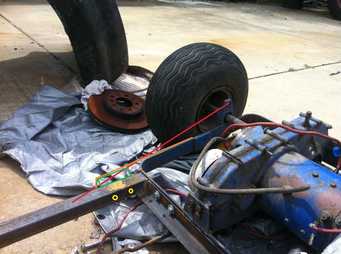
Here's a better shot of the connection. The red line was where I was considering triangulating it a bit but it would foul the motor on the other side so that may not work.

I have to add on to the rear frame to make a support for the hammock in the back so I may design that so I can triangulate to it.
Very open to better ideas, there has to be a stronger solution to this.
I bet you could do a square tube right on top of your perimeter frame that bolts on the front and is either notched to clear the axles or is raised above them and welds to the back of the motor frame. I bet a lot of the flex is ust from the metal strap of the motor frame, if you had something stronger that spread the load to the rear it would help.
Actually I wonder if you could do something like this:
orange = strap the same thickness as the motor frame, green = square tube, yellow = bolts. Yay for paint.
where you weld another strap to the side of the motor frame that runs up alongside the perimiter frame then have a piece of tubing that bridges the gap welded to either side and then the two would bolt together there, too. It would get the load spread onto the vertical strap of the motor frame and into two dimensions of the frame at least.
JThw8
UberDork
7/31/12 11:34 a.m.
Yeah, that was a thought running through my head as well, I think it's a good one and I have plenty of tubing to work with so I'll give that a shot. Going to be away for a few days so no progress until I return.
JThw8
UberDork
7/31/12 12:48 p.m.
Ok, so you convinced me. Made a slight modification and just bent the strapping to fit rather than fill the gap with tube.


Greatly improved. Now when I bounce on it all the motion is from the balloon tires, no flexing in the frame. Great idea Dave! Thanks :)
Once I get the good hardware I think I'll tack the bolts in place so I can put it together with one wrench. I'll also round off the front of the braces when I tear it down for paint.
JThw8
UberDork
7/31/12 12:56 p.m.
Some other info on the build while I'm sitting here. It was originally a 36v cart. Speed is controlled by a "wiper" arm and there's only 2 speeds slow and fast. When the pedal is depressed enough to move the wiper to contact for slow it sends the power through a resistor. When it moves further to fast it just sends full voltage. I wanted it slower than it was and resistor style slowing is very wasteful of the stored energy but I didnt want to shell out the money to convert to solid state either. After over thinking the idea for some time with an EE friend of mine the answer came from a poster here in another thread. "just run it on 24v" doh...that's so simple its perfect. And at 24v the speed is just where I want it. It uses 3 12v deep cycle batteries and Im going to keep all 3. The 3rd will separated from the other 2 and can run lights and such and then when I charge it I can just hook it back into the pack so I can still use the 36v charger.
make sure to build in secure weed storage for the buffet concert.
and a margarita blender.
JThw8
UberDork
7/31/12 1:03 p.m.
patgizz wrote:
and a margarita blender.
Already in the "if we have time" pile of plans :)
Almost real time updates. 11:07 dculberson posts a suggestion and by 12:48 JThw8 has incoporated it!! 101 minutes from idea to pictures of it implemented!!
JThw8
UberDork
7/31/12 1:21 p.m.
Adrian_Thompson wrote:
Almost real time updates. 11:07 dculberson posts a suggestion and by 12:48 JThw8 has incoporated it!! 101 minutes from idea to pictures of it implemented!!
Sorry, I stopped for lunch ;) Actually it just takes forever to drill those holes.
That is awesome!! And I'm glad the idea helped.
Definitely round those ends off, it would do a number to a car's interior or even worse, your shins.
JThw8
UberDork
8/6/12 7:54 p.m.
Finally home from vaca, just got a little done before I lost daylight tonight, spent too much time staring and thinking and not enough cutting and welding. Added the start of the front hammock mount. It will need angle supports added but overall it does the trick.

JThw8
UberDork
8/7/12 6:49 p.m.
More progress tonite!
I got the rear hammock mount installed and gusseted. The front is actually notched around the front support bar and very strong but since the rear was welded to flat strapping the gussets seemed helpful.

Then I boxed in the corners to help prevent twist in the rear frame, there will also be support braces triangulated from these to the hammock mount for additional strength.

Ta-da...mockup complete. I was able to sit on it but I didnt put my full weight on it as the rear upright is just for mockup and not strong enough to support much weight without bending. The front bar is 1.5 inch OD with 1/4 inch wall, plenty strong, I just need another length for the rear. The bars are removable to break it down for loading in the wagon.

JThw8
UberDork
8/10/12 6:10 p.m.
Half day friday at work so that means more progress. Started with a trip to the steel supply, I love that place, so much potential (they sell industrial hardware too)
So first I added braces on the rear mount

I also added some corner bracing up at the front

Then my wife took it for a "test ride" so I could determine where the hammock needed to attach to the supports and measure clearance for the battery packs. (I didn't point out that the hammock was held in place by vice grips until she was done)

With that sorted out I could make "hangers" for the hammock. Since most of the weight is borne by the pole it's self their real purpose is just to keep the loops from sliding down the pole. I just slotted some angle iron and bent it around the pipe then welded it up.

As much as I've stiffened it up the poles act as levers so there is still some flex where the front and rear join. It seems as though it will hold up but I'm contemplating redesigning things so the front frame is the full length of the vehicle and the powerplant subframe mounts on top of it. I did a test and as it is I can fit the whole thing in the wagon in one piece if I move the driver seat forward a bit.
Great job! Is it possible the flex is in the poles themselves? If it is, it's not really a big risk for failure as mild steel tubing can withstand a lot of flexing... might make the wife nervous though.


