
I picked up a cheap Chinese universal wiring harness for the Midlana project at a swap meet. Why spend 200 to 300 bucks, when I can spend 50 I thought... well I think I figured out what that extra money gets you... complete instructions in English.
The quality of the harness seems fine, the issue is that the diagram on the single page of instructions doesn't match the actual unit. The table in the directions also doesn't match the unit or the diagram right above it. I colorized diagram to match the harness, it was impossible to follow as received and didn't totally match the diagram.

The basic layout is easy enough to understand, there are 4 bussed groups of fuses. The relay controls the horn. Even if the labels don't match the diagram the circuits can power whatever I want if I change the sticker on the cover of the box.

What I can't figure out is the turn signal flasher. It is a 2 terminal style flasher. In every other wiring diagram I have seen the flasher is in series with the positive wire to the signals. On this thing one side is connected to the a fuse on the "always hot" bus, the other side is connected to a fuse on the "hot when ignition is on" bus. Both of these will be at +12V when the ignition is on. How is that supposed to work? The input and output wires shown at the flasher don't exist, only the two black wires that run to the fuses.
It seems to me that one side of the flasher should be disconnected and run to the turn signal switch, but I've been staring at it so long my brain may not be working fully. Am I missing something?
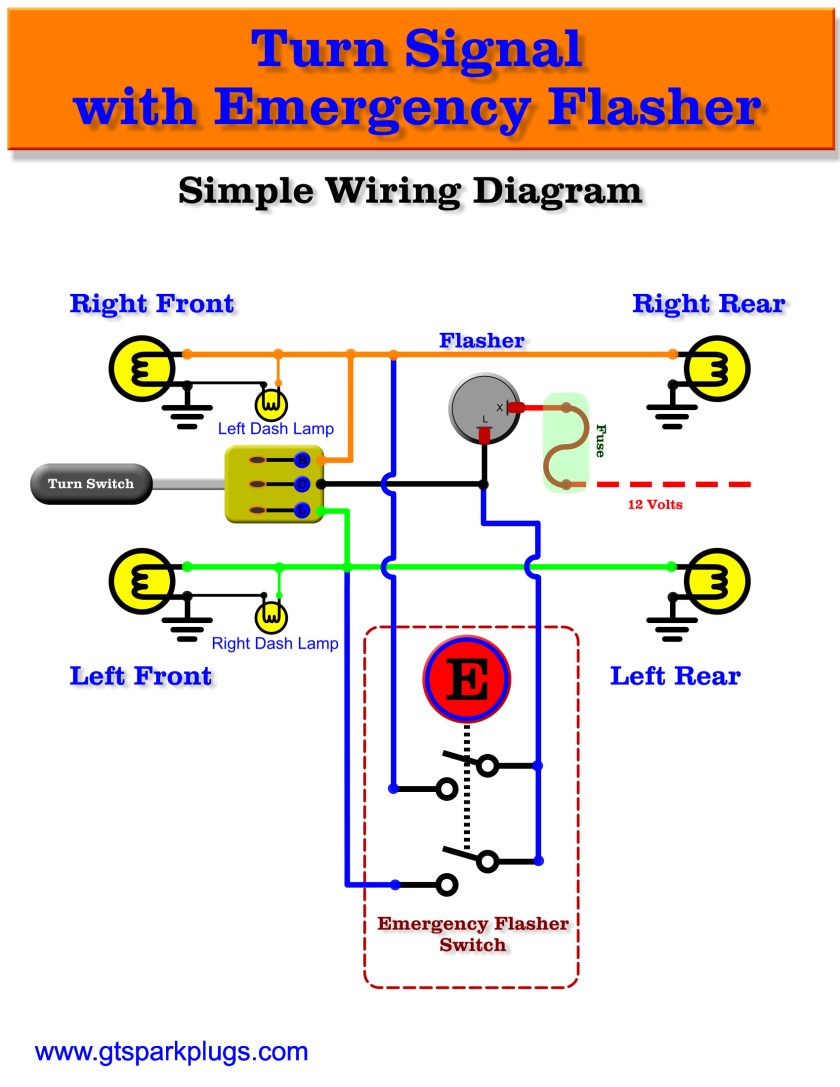
Looks like I'm not the only one perplexed.
One reason why I avoid Chinese products at all cost. Good luck figuring this one out.
Just ordered the same one on ebay, i'll tell you in a couple weeks.
There's another relay for the flashers. One specific for that- so that output is probably the power to the flasher relay. Which has 2 other inputs- one for right, one for left. The emergency flasher turns on both.
Since you are doing your own car, are you planning on LED lights? Or regular incandesant? If you get LED's, you need a specific digital flasher realy- as the incandecent relay actually uses the resistance of the light bulb to time how often it flashes (which is why it flashes faster when one bulb is out).
It's not the output it's the outpet. It's where you hook the cat up that yowls every time the flasher relay fires.
In reply to alfadriver (Forum Supporter) :
I believe the single flasher relay provided on the box can be used for both turn signal and emergency flashing. Even using two I can't see how the one provided would be able to function with the same voltage on each pin.
I'm going to use LEDs. This flasher relay claims to work with LEDs but I'm dubious.
Not sure about that wiring diagram either- not an electrical person- I'm not specifically familiar with the normal grounding path to make turn signals work. But having all of it fed by one 12V power signal would be correct. Normally, all injectors run from a common, single, 12V power supply- lights are a piece of cake, especially turn signal lights.
I'm not sure how it works when you have the same flasher for emergency (4-ways) and turn signals, but I do know that bgkast's diagram fits what seems correct.... except one thing. The 12v power going to the flasher would need to somehow be split into hot and switched so the 4-ways work all the time and the turn signals only work with ignition power.
I would think a relay (rigged to come on only with ignition power) in line between the turn signal switch and the flasher would do just fine, but I'm not sure how that would work in your fuse box with both pins getting power with ignition.


