I recently gotten involved with the Formula SAE team at my school. They have lost several times in the past because of faulty wiring. They have asked me to do the wire splices, since I seem to have the most experience with it. My question is, how do you guys do your wiring? My father always taught me to use butt connectors, solder, and then a shrink sleeve similar to this picture:

However, I have heard some people claim that soldering is not the way to go, and my team members had loosely agreed ,"No soldering this year." I think I can convince them to allow soldering, and I feel that soldering is the way to go, but I am open to other viewpoints. Also, I found that the NASA standard involves soldering the connection.
http://makezine.com/2012/02/28/how-to-splice-wire-to-nasa-standards/

Anyways, I'm ranting, and I may have answered my own question. Tell me what you guys think. I'd love to have more opinions as this seems to have been the teams breaking point for the past several years.

wae
HalfDork
1/21/15 8:24 a.m.
I've had good luck with weatherproof, heat-shrink butt connectors (properly sized for the gauge wire I'm working with, of course!) for splicing when necessary with no solder applied. I have done some soldered splices, but have basically interlocked the strands of the two wires, twisted around the axis of the wire (so that the two wires remain basically straight, as opposed to making a pigtail thing in the middle of the run), and then applied flux and solder.
Something to note is that what you've referenced is specific to solid conductor wire, not the braided type of wire that I suspect you'll see more of. I looked up the NASA specs that you're talking about and they call for soldered or crimped splices with several different types of splices being "approved". The full document is here: http://www.hq.nasa.gov/office/codeq/doctree/87394.pdf and splicing begins on page 80.
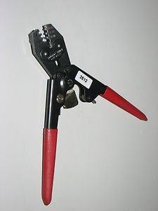
If you have a good crimper, the kind that ratchets down and won't release until it has completed the crimp, there is no reason to solder. A proper crimp effects a pressure weld between the wire(s) and the lug.
If you are good with solder, and you thoroughly clean up the flux after the solder cools, than there is no need for a crimper. The problem is that most people are not good, resulting in cold joints or bad solder connections and they either use plumbing solder or don't clean up after the soldering (or both) and leave acidic flux on the copper wire to corrode it and ruin the connection.
On something like an SAE car there is no reason to splice wires together. Install a couple of terminal blocks, barrier strips, molex plugs, or weatherpack connectors anywhere you want to change things later and run continuous wire from those points to their destinations, with appropriate terminal lugs properly crimped on and you will be fine.
Strictly speaking, that splice in your illustration above is called a Western Union splice, or lineman splice: http://en.wikipedia.org/wiki/Western_Union_splice It was developed way back in the telegraph days.
A properly done mechanical splice is generally considered better than soldering, but that's the key - if it's done properly, with an appropriate connector and crimp tool. The issue is that a soldered connection forms a stiff spot in the middle of the wire that could fatigue over time from vibration, and there's also the possibility of a cold solder joint.
The best thing to do is avoid splices and then you don't have a problem either way.  Maybe you can make wire junctions at terminal strips instead.

wae wrote:
I've had good luck with weatherproof, heat-shrink butt connectors (properly sized for the gauge wire I'm working with, of course!) for splicing when necessary with no solder applied. I have done some soldered splices, but have basically interlocked the strands of the two wires, twisted around the axis of the wire (so that the two wires remain basically straight, as opposed to making a pigtail thing in the middle of the run), and then applied flux and solder.
Something to note is that what you've referenced is specific to solid conductor wire, not the braided type of wire that I suspect you'll see more of. I looked up the NASA specs that you're talking about and they call for soldered or crimped splices with several different types of splices being "approved". The full document is here: http://www.hq.nasa.gov/office/codeq/doctree/87394.pdf and splicing begins on page 80.
Awesome answer.
Other things that aren't 'splices' but will get blamed on 'wiring':
- bad grounds (I should put this like 3 times because it is so important)
- poor wiring plan (i.e. we added this at the last minute and just grabbed the hot from the coil wire = no no)
- incorrect wire type (size, strands, even multiple wires of the same color makes things really hard)
- bad wire protection (it is protected from snags? heat? too much bending? is it easy to access in the heat of the competition if something does go wrong?)
- not tested well enough (we added this at the last minute and it worked fine, but we didn't go back and test all the other systems because they 'shouldn't' be affected)
My personal feeling on splices is solder or crimp is fine. Just make sure whatever you do, you do well. (search for crimping tools here, you will find the right ones to use to make great crimps).
We already have the crimping tool that ratchets down, and we plan to use butt connectors. I will discuss further with my team.
Also, they know for sure that the wiring failures in the past have been because of bad splices. I will keep in mind the other wiring failures for a later date though.
I have seen on factory wiring harnesses that they generally us one big power wire for all of the sensors, and split off as needed. How do you guys feel about this?
We use environmental splices on aircraft:

They'll require "environmental crimpers" for the barrel portion and a heat gun for the shrinkable tubing you see in the picture.
It's expensive, but the result is a splice that is as strong as a wire. There are also aircraft grade terminal lugs for grounds and "red and blue" crimpers for those as well. Anything rated for use in aircraft should handle the vibration and heat requirements for your FSAE racer (although there are high temp options available if needed).
However, a properly soldered connection could give you the same results. If properly done (and protected).
Rcutclif's post has a lot of good points. Also support the wires (at least every 12 inches), run your bundles intelligently, avoid chaffing, and all that jazz.
Best of luck to ya'll.
Instead of running one wire and branching to every sensor, what about running one wire to a terminal block, and running the sensor power from there?

One wire to the terminal block, a bus bar down one side and pull power to your sensors as necessary.
but keep in mind, any failure of the wire leading up to your terminal block will be a single point of failure for all your sensors.
My general rules about splicing:
-
Crimped splices are unforgiving of bad tools, but get the right equipment and you don't have to worry too much about technique.
-
Soldered splices are unforgiving when it comes to bad technique, but get the right technique and you can pull them off with cheap tools.
-
Whatever you do, use heat shrink tubing or other suitable covering that provides both sealing and strain relief.
one word: wire nuts 

in all seriousness though i have a hard time soldering wires (shaky hands and having no patients) but i have always had luck with the heat shrink butt connectors, its what we used on literally every wire splice we did when i worked at the county and they never gave us any problem, just use good quality ones and make sure the wire is good and crimped.


T.J.
PowerDork
1/21/15 9:28 a.m.
I typically use something like the Western Union splice above, although I never knew it was called that. I don't solder. I twist the wires together and use heat shrink. No solder, no crimps. I have a car full of splices done in this manner and haven't had an issue in the past 8 years or so since I re-wired the car.

Don49
HalfDork
1/21/15 9:49 a.m.
I also use the Western Union splice when the connection doesn't need to come apart. Otherwise, I use spade or bullet connectors.
I don't have much of a scientific reason behind it, but I solder and heat shrink everything. It's pretty obvious when you have a cold joint, and if you're any good at all, that's pretty easy to avoid. I've also never had a brittle failure, though I could see how that would happen. Generally, I try to restrain the wires such that they can't bounce around all the time anyway.
I've crimped some things in the past when in a pinch, and even using a proper tool, I've had a few fail years later. Could be something wrong with my technique, but I still prefer to solder when possible.
The quality of the wire being used has a lot to do with it too. Not all wire is the same. I don't know the specs or standards for wire used in automotive applications, but definitely some types are stronger than others.
If the team was previously using the cheapest, most brittle wires, even properly crimped or soldered connections could easily fail.
I'm 99% sure there problems in the past were in method and not in wire quality.
I must say I'm not a hug fan of the terminal strip in this application. What are the advantages of a terminal strip? Ease of troubleshooting? Expandability?
You won't find any solder joints in a mass production vehicle harness. As noted, they tend to create failure points. Put me firmly in the ratcheting crimp tool, heat-shrink connector camp. Always give the wires a tug after you crimp them to make sure you didn't get a misfire.
Instead of a terminal strip, I'd get a fuse/relay block.
http://www.delcity.net/store/Sealed-Mini-Fuse-&-ISO-280-Mini-Relay-Panel-with-Bussed-Inputs/p_803800
wae
HalfDork
1/21/15 10:23 a.m.
TheV8Kid wrote:
I'm 99% sure there problems in the past were in method and not in wire quality.
I must say I'm not a hug fan of the terminal strip in this application. What are the advantages of a terminal strip? Ease of troubleshooting? Expandability?
If you have, say, multiple sensors that need a common power and/or ground, rather than putting multiple potential failure points in the form of splices you can run the common to the terminal block and then a direct run from the terminal block to each of the sensors. You'll have a good mechanical connection for each one instead of having a potential failure because a splice comes apart. It's also much easier to add additional circuits later or to change things up a bit -- for example, if you have to move a sensor and the existing wire isn't long enough, you can simply pull that one wire out and replace it with a longer one.
As mentioned, the downside is that if you lose the common wire for some reason, everything dies.
wae wrote:
As mentioned, the downside is that if you lose the common wire for some reason, everything dies.
The upside is that it's equally easy to see if you have a power supply problem or an individual sensor/circuit problem.
"We lost the O2 sensor!"
"Is EGT still responding?"
"Yes."
"Okay then, either the O2 sensor failed, the wire(s) failed or the fuse popped only to that."
Edit: Put me down for one vote for "crimping," I've never had one of my racecars (chumpcar endurance racing or track days) down due to a wire that I crimped!

Hal
SuperDork
1/21/15 10:52 a.m.
Keith Tanner wrote:
You won't find any solder joints in a mass production vehicle harness. As noted, they tend to create failure points. Put me firmly in the ratcheting crimp tool, heat-shrink connector camp. Always give the wires a tug after you crimp them to make sure you didn't get a misfire.
I agree. I always use crimp connectors and terminal/fuse blocks where needed when doing automotive wiring.
With solid wire it is easy to solder and make sure it is not a cold joint by looking at it. But automotive wire is stranded, not solid. It is easy to get a solder joint on stranded wire that looks good on the outside but was not hot enough for the solder to penetrate all the way to the inner strands. This results in a joint the is both mechanically weak and has poor electrical conductivity.
I learned to make proper connections with salt-proofing and strain relief from an old school Navy RADAR engineer. "Hank" would come around with a wire cutter and destroy your E36 M3 if he didn't like the looks of it and then you would have to do it all over again or fail. I thought he was a colossal shiny happy person at the time but almost 30 years later I can still wire the E36 M3 out of anything and trust it to last forever.
Still, when I'm lazy I use a crimp tool. It's ugly and bulky but if you do it right it's just as good provided you proof and strain relief it the same way.

pres589
UltraDork
1/21/15 11:09 a.m.
How many sensors in an automotive application need to common their grounds to a single spot with other sensors? I would think that if the sensor ground isn't required by the ECU or similar logic box, the wise move would be to collocate the ground near as possible to the sensor. Same as power devices, save for rare instances like high power usage items, like the A/C compressor clutch.
I like the idea of a terminal strip or something similar that makes it easy to trace power to a common point as well as keeping the engine bay harness a bit easier to add to or remove.
The NASA splice without solder is called a Western Union splice (as in the telegram company), works fine, even with multi strand wires(twist the stripped wires tight first). I prefer to solder it but there are a couple field repairs I've done on my cars with just the splice and marine shrink tubing and they hold up fine.

44Dwarf
UltraDork
1/21/15 11:29 a.m.
You do find soldered connections / splices in motor cycle harnesses all the time. splices fail often cause they are not held firm, you can put a splice in the middle of a 4ft span and not wire tie it down the added mass will make the splice flex and fail.
pres589
UltraDork
1/21/15 11:37 a.m.
In reply to Kenny_McCormic:
I'd think that you'd want to take the "NASA splice" above and tie it to structure at the splice point, especially if soldered, to try and control that mass in the middle of a wire run from swinging around and stressing on the ends of the splice. If you did that I think it would be a pretty solid connection.
In reply to pres589:
I find the marine grade shrink tube to make a good enough stress relief, but it can't hurt to tie it down or to another wire.


