I have been designing a chassis for the past month and I am aware that the trans tunnel is incomplete, but before I complete it I was wondering if any of you could spend some of your time, shedding some constructive criticism on how the chassis looks to you in terms of safety and rigidity. I would like to add more bracing in the rear end but first I would like to know if I'm heading in the right direction before continuing.
My main objective is safety first, then lightness, and finally rigidity.
Sorry I forgot to post the most important part, the pictures.
Alright, your critiques please! 


RossD
PowerDork
9/30/13 4:27 p.m.
What is the drivetrain setup? Front engine, rear wheel drive?

mndsm
UltimaDork
9/30/13 4:32 p.m.
What's connecting the rear of the main frame rails to the back of the chassis? Seem to be floating.
That's... a lot of metal. With a lot of open box sections.
I always liked the idea of a pair of 2" tubes for each frame rail, plated over on each side with 2" 16-gauge strips. Should be really stiff for the amount of metal used.
IMO, don't worry too much about safety - in anything small, you're exposed enough that there's no point. Make a roll cage around the passenger cabin built to best practices and call it good enough.

bmwbav
New Reader
9/30/13 4:49 p.m.
In reply to dragoon119:
No idea myself, but definitely check out the locust forums, this is what they do.
http://www.locostusa.com/forums/
You've made some interesting choices there.
Some tube dimensions would be nice to know. Also without the suspension design analyzing the chassis is going to be limited to the roll/crash structure and overall estimates of stiffness. Give us some more details on what this is for and I will work up a proper constructive critique tonight.
I'll be brutally honest. Extrapolating the tube cross sections from the fact that the chassis is car sized, they're generally much larger than they need to be and in the wrong places.
-
The braces on either side of the front box are pointing the wrong direction.
-
There's a general absence of actual triangulation.
-
Windshield frame begins at the bottom of the footwell?
I'd suggest modelling the wheels, suspension components, major mechanical components, driver and passenger. Calculate weights and dimensions and connect it all with tubing. And triangulate the berkeley out it.
Read all of this: Lotus 7 clone chassis
It's a great start. And if you have a MIG welder and a chop saw, buy a bunch of tube and make some stuff. It'll help drive your process.
Better yet, see what other people have done before, and copy them.
The Ferrari restorations/rally conversions in the Projects section of www.mat.fi show that those 308 frames look very, very basic. You got your passenger compartment, and then you have frame that goes out to where the suspension pickup points are, and then anything else just sort of hangs out there. It's not super important that the radiator be securely mounted other than making sure it doesn't fall down or flop back and forth, while keeping the upper and lower control arms in place is critical.
Oddly enough, if you get a sample of what other semi-tubeframe cars from the era looked like (easiest to see are clamshell-opening Group B cars like the Delta S4 and the 205) they are all the same - you got a passenger compartment, and enough structure to securely attach the suspension to it, and everything else is secondary.

Leafy
New Reader
9/30/13 7:28 p.m.
That looks wicked heavy, while also not being very stiff. Remember, a chassis is a frame which locates the inner suspension pickups while locating the engine and rest of the drive train, having a spot for the driver is the 3rd concern. So the chassis should build off the suspension pickup points and connect them together, while also connecting the engine, trans, and diff mounting points together. Right now it just seems like you've made a few boxes with some triangles and connected it all together. If this is solidworks, weldments are your friend.
I didn't even notice the giant cross-sections underneath the driver...
There should be no frame underneath the floor unless you're building an SUV. The driver sits between the frame, not on it.

It's a good start, I don't know a damn thing about Solidworks so cannot comment there. Please take these comments from us as constructive!
I too recommend you triangulate and go with smaller tubing, that winds up being much more rigid than larger non-triangulated. There have to be compromises for service accessibility etc but that can be addressed by having bolt in X braces or perhaps sheet metal on one side of a 'box', for instance a sheet of 20 gauge sheet steel on one side of an open box with a central opening for, say, an exhaust header gives at least as much rigidity as a tubular cross brace. Here's a good example, a Porsche 550 Spyder bulkhead:
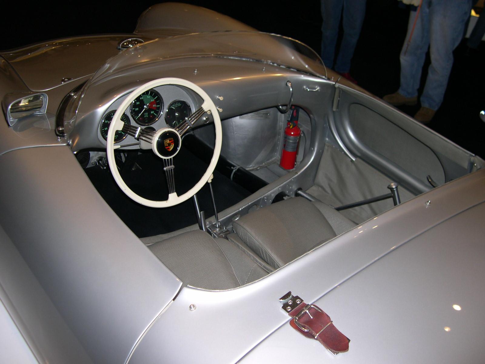
There's a big opening for the drivers and passengers legs yet the oval 'ring' adds a bunch of stiffness.
The windshield frame would be a great start to a roll cage which would add a tremendous amount of stiffness in the center. As it is, the design shown here has no real lengthwise or torsional stiffness in that area.
A good book with basic design info is Herb Adam's 'Chassis Engineering'. He discusses all these points with lots of pics to show what he's driving at.

Something which will help tremendously is to learn to visualize a 'load path'.

In reply to mndsm:
I'm not finished with that let...
I'm gonna connect them to the rear of the frame but they are larger than the rear section so I will have to neck them done to connect properly. Will this reduce rigidity?
mndsm
UltimaDork
9/30/13 8:47 p.m.
Those two rails in particular are MASSIVE overkill IMO. I'd lose em altogether. What these other people smarter than me are saying is correct though- smaller gauge, more triangulation. Triangles are much stronger. As an excercise, build it with toothpicks. smash it into something. Then build a triangulated one, smash that. You'll see where the failures could be. And while not an apples to apples comparison, it gives you an idea- and smashing things is fun!
Leafy
New Reader
9/30/13 8:52 p.m.
Can you post a 3d model file of either solidworks or step format that only has the inner control arm mounting points, the engine, tranny, and diff mounting points, but no structure connecting them? I mean just a 3d sketch with some points in it. I might be bored at work this week and take a stab at some rough chassis design.
In reply to motomoron:
Thank you for being honest but I gotta ask, why are the braces in the wrong direction? In a frontal crash wouldn't they provide reasonable protection?
I have provided triangulation for side impact and will be putting more in the rear frame but do I need more in the frontal section of the vehicle or passenger compartment?
The windscreen is attached about an inch under below the top of the firewall.
As the others said, I would recommend some triangulation. From my time in FSAE frame design boiled down to a few basic rules:
- The frame is just a big bracket that holds all your stuff. Get your required components in place and design around them.
- Triangles are good, squares not so much.
That's all I got.
In reply to Leafy:
What if I decrease the thickness of the tubes to 3/18? That should shed some weight off of the frame.
When I was designing the chassis I was thinking weight distribution, roll center, and center of gravity. Safety was a big concern so I factored that in with some large rectangular tubing along the sides and inner tunnel. I also wanted an X-frame like the Lotus Elan and S2000 but at a low, centered point in the car. It seems this didn't pan out like I thought it would...
In reply to Knurled:
I put those in for side impact protection so I guess they are not needed?
In reply to nocones:
Alright time for the answer you might be dreading..........
....I'm am still a noob at suspensions. Don't get me wrong I understand things like unsprung weight, Camber, caster, etc but I am still trying to design my own suspension and am have a very hard time with it. At the moment I've been looking into using the Knuckles off of a front wheel drive vehicle on this car. To make an independent double wishbone front and rear setup. I was thinking of going in-board for both the front and rear suspensions.
Leafy
New Reader
9/30/13 9:16 p.m.
dragoon119 wrote:
In reply to Leafy:
What if I decrease the thickness of the tubes to 3/18? That should shed some weight off of the frame.
When I was designing the chassis I was thinking weight distribution, roll center, and center of gravity. Safety was a big concern so I factored that in with some large rectangular tubing along the sides and inner tunnel. I also wanted an X-frame like the Lotus Elan and S2000 but at a low, centered point in the car. It seems this didn't pan out like I thought it would...
Decrease to 3/8th or 3/16th? If you redesigned the frame construction itself to be better you could drop those down to 1/16th wall without really noticing a stiffness loss since they're so massive. And I don't like square or rectangular tube in chassis, it is a bit easier to work with than round but it doesnt quite give you the as good of a stiffness to weight ratio. There are spots to use it, like the pickup points for control arms and shock eyelets for example.
If you arent going to design the suspension and want to do double wishbone everywhere, just use miata bits, they're plentiful and handle properly.
 In reply to motomoron:
I acutally used the Lotus 7 as inspration for my front end but I see that they are using it for the engine compartment side, not the actually front of the vehicle.
In reply to mblommel:
Where? Below the engine compartment, tunnel, firewall, and rear roll bar? Is that where triangulation is needed more?
In reply to Leafy:
I really don't wish to use Miata bits if I can help it. I believe the satisfaction of designing my own suspension will be well worth the effort. Besides it gives me more time to familiarize my self the terms, actions, and physics involved to help me with my next build. If this one doesn't bankrupt me first!


