Ok this is completely nuts to even think about this but could you suspend a subi motor below modified frame rails?
IE: move the frame rails up to the top points of the suspension attachment points and just add some brackets for the lower suspension attachment points and then mount the motor in the middle suspended off the frame rail that is now in effect above the center line of the motor?

Ian F
SuperDork
11/11/11 1:29 p.m.
Hmm... I suppose it's possible. Although I'm mentally picturing a high-frame (ala a uni-body car) with the lower suspension (or maybe even the entire suspension and engine) mounted to a sub-frame bolted on from below - with the engine sort of between them.
In reply to dean1484:
I don't know about the motor part, but one thing concerns me about this arrangement (not that it can't be overcome):
The higher loads are on the lower control arm: Looking at forces in a corner, the lower control arm is carrying in compression the entire cornering force of that tire plus the tensile load on the upper control arm... I think. Basically, for the tire not to flop over around the lower ball joint, the forces on either side have to balance. The relative distances from the ball joint will affect those forces, but they do have to balance.
So, not that appropriately stiff brackets can't be made, but in terms of putting the strong bits where the big loads are, it seems suboptimal...
Ian F
SuperDork
11/11/11 1:45 p.m.
Agreed. That's why I was thinking sub-frame vs. trying to hang brackets. Much easier to triangulate with a sub-frame.
After getting a good night sleep I also agree. The engineering for that would be tricky at best. I really like the idea of taking the subframe and moving it over. All tech engineering of the front suspension, steering and motor mounts are solved.
I can not leave well enough alone. Getting back to my original idea. You could make the motor part of the frame? IE: make it take the loads from the lower suspension points? The motor would become a part of the frame / structure of the car and not just a lump supported by a frame?
Dam.. .. I think way to much.

Grizz
HalfDork
11/12/11 12:43 p.m.
I really have nothing to contribute to this thread, but I want to make a title called "I bought a LBC with a BBC" and have the contents be about a Jensen Interceptor just to confuse the hell out of people.
As far as engine suggestions, I've wondered if the 2.6 from a Starion would fit into a Spit a couple of times.(Mostly every time I see a starion or a spitfire)
Curmudgeon wrote:
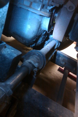
Aha. The other bolt (just barely peeking out under the control arm) is actually the nut for the stub axle. Do you think it's possible to sneak the rack in between the balancer and the front cover, the way it's done in the pic of the Spitfire? If the engine is scooted back an inch or 3, those together could get the steering where it needs to be without resorting to rear steer, etc. You only need 3/4" or so clearance.
Looks like the rack can move another 1.5" back or so if I cut the framerails a little more (there's about 2" of total clearance between the rack body and the oil pan):

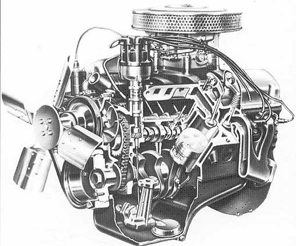
There's more room than I thought and if you notch the pan even more. That looks like a 4x4 or Bronco pan, which was rear sump. Moving a rack is not a small undertaking, if you are going to do it you need to fix the steering as best as possible. Checking this image, there's actually a good bit of room to notch the pan in the area where it needs to be done. No, the circle is not where I'm talking notching! That was put there by the guy I stole the image from. 

A long shot but one to think about: you might be able to lower the rack and help with the clearance issue yet keep the steering geometry in good shape.
Here's what I'm thinking:
The steering tie rods need to be parallel with the lower control arm. In your pic here, they look pretty close to that ideal.
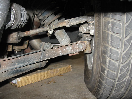
If you need to, you should be able to take the bolt on steering arms and swap them side to side. This will turn them upside down, meaning for the tie rod taper to fit the outer rod ends will be flipped over. This means you could lower the steering rack ~ 2" and still keep the tie rods parallel to the lower CA's. The only problem MIGHT be that the rack would interfere with the lower inner control arm bushings. If flipping the arms can't be done, the holes can be filled with weld from the top, then they can be taper reamed from the bottom. Speedway Motors sells the tapered reamers.
From what I've read/seen in pictures, the rear-sump pan is stock on the Mustang 5.0. There's an oil pickup tube in the front "mini-sump" so I would need to be careful to allow room for that if I notched it. I'm sure there's some room to be gained, though.
Regarding the lower control arms, I confirmed that they're not parallel because the chassis pick-ups are dropped as compared to stock. The upper control arm chassis pick-ups seem to be stock, so the geometry is probably non-ideal. I'm really considering re-engineering the whole front suspension with Miata spindles. That would also give me bigger brakes and more options going forward for brakes, pads, wheels, etc.
Oh, and I might need this plate before it's all said and done:


OHSNAP' is right.
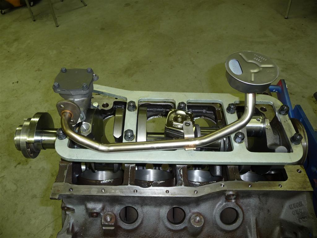
The 302's oil pump hangs down low in the front but there's still a good bit of room for pan notching.
The rear sump Fox body pan has a rear pickup with a long tube and the double humps due to the oil pump layout..
Having been down the Miata knuckle road, let me suggest that you start with some of those threaded ball joint sleeves available from AFCO etc instead of adapting the Miata ball joints. The Miata parts are just fine and work great but man the amount of fabrication on the control arm is a PITA. Use TR6 upper ball joints, they fit the Miata taper and bolt to the Spitfire upper CA's. Saves a lot of aggravation. Use the Miata outer tie rod ends but tap them for 1/2-20, then they screw right on to the Spitfire inner tie rods.
Well, as with all things GRM, Miata seems to be the answer yet again. I've decided to yank the 5.0/T5 and sell them off, and drop in something smaller. I found a wrecked '94 Miata that's being parted out locally and am going Sunday to witness the engine running in the car before the guy pulls it and the trans for me. The BP will fit easily into this car's expanded engine bay, and should I want more power down the road, it can be turbo'ed without issue. Sure, this isn't as exciting as some huge engine -- but it should make the car much more pleasant to drive and work on, and the parts availability/power/price triangle of the BP is tough to beat.
I also ordered a Speedway Motors wiring kit (20 circuit, 'cause it was only marginally more money than the 12 circuit), so hopefully electrical trouble can be headed off at the pass.
 I understand your reasoning, but I really wanted to see that thing work with the V8.
MG Bryan wrote:
I understand your reasoning, but I really wanted to see that thing work with the V8.
Me too. It's taken 4 months of me looking at it every which way to finally admit that the 5.0 is really too big. Clearly it can be done, but I don't really want the final product and everthing it entails (bad steering column routing, sub-optimal steering rack location, a ridiculously-cramped engine bay, etc.).


