
In reply to mke :
I've been under the impression threads for that sort of application are typically rolled?

Ian F said:In reply to mke :
I've been under the impression threads for that sort of application are typically rolled?
Yes, they are rolled and it turns out for a very good reason that has nothing to do with lower production costs....they break if you don't roll them. Lesson learned and set 2 is rolled.
TR heads use a center outlet cooled to get flow more balanced.

The 400 heads do not and connect water pump plumbing in the timing cover, because why wouldn't you chain drive the water pump and plumb it through the timing cover?

That won't do.....that stuff came off the timing covers and I added a coolant feed that goes straight to the port in the block.


Then there needs to be some way to connect to the heads and someway to flow out the end....first add something to connect to that points in a useful direction


Then some kind of manifold pipe....maybe a cut down 308QV part will work.....


A thermostat would be helpful....this thing on ebay might work 96 mustang I thing it was

Just needs a couple tune-ups...and it needs to connect to the manifold thin I made and a hose won't fit


A top that points the right way ands clears the fuel rail.


Then some way to connect to the radiator tube and also some way to get the waterpump to connect to the engine


I just cant get over your ability to knit stuff with a TIG torch.
Seriously.
Pete
I did some work like this on aluminum, while flipping the intake manifold on an Acura 3.2V6. I used a spool gun MIG setup. I haven't tested it yet for leaks. In general, I have difficulty welding plumbing (liquid or air) and making them not leak. I would think you'd have better results with TIG.

Im I the only one who got to page 11,where he puts the cylinders in the block, and just sorta assumed that there was going to be some horrible drama that meant that no pistons anywhere would work and so no worries he will just fabricate his own by laying repeated tig beads inside a clay mold? Srsly... after all this, store bought pistons seems almost like cheating!
Jay_W said:Srsly... after all this, store bought pistons seems almost like cheating!
LOL,,,,,at some point a little cheating with store bought custom parts is nessesary to maintain what little sanity I have. ;)
carwhisperer said:I did some work like this on aluminum, while flipping the intake manifold on an Acura 3.2V6. I used a spool gun MIG setup. I haven't tested it yet for leaks. In general, I have difficulty welding plumbing (liquid or air) and making them not leak. I would think you'd have better results with TIG.
I have tried mig welding alum....tig has got to be 10 or maybe 100 times easier to get a sealed bead. You'll probably never notice a pin hole or 2 on an intake or header but water tube need to be sealed and that can mean a few weak test and reweld cycles with a mig....or tig it and be done,
Was wondering if you'd post about this somewhere now that the difficulties on that other forum happened. I have to say though that you've inspired me to go digging into the enginelab stuff and holy cow that solves some problems I had.
Oh yeah and the fab work of course; holy cow. I feel like it would almost be easier to do new castings at this poing!

Oh no, Ford parts. Now Enzo is really fuming.
GCrites80s said:Oh no, Ford parts. Now Enzo is really fuming.
I know, I know......

NOHOME said:I just cant get over your ability to knit stuff with a TIG torch.
Seriously.
Pete
I second this .....I truly have nothing to offer in way of 'constructive criticism', but what I sense is this is nothing more than an engine, regardless of the lineage that you are fortunate enough to have the time, knowledge/skills,and the facilities to execute....so therefore onward and upward......excellent work maestro!
Am guffawing in my beer. Still. Why? Cuz of the lil tidbit this artiste discovered, to wit, that ring gear teeth interchange twixt Ferrari and GM. Thx for that! This is one of those trivia treasures that will effortlessly stick in my brainpan forever.

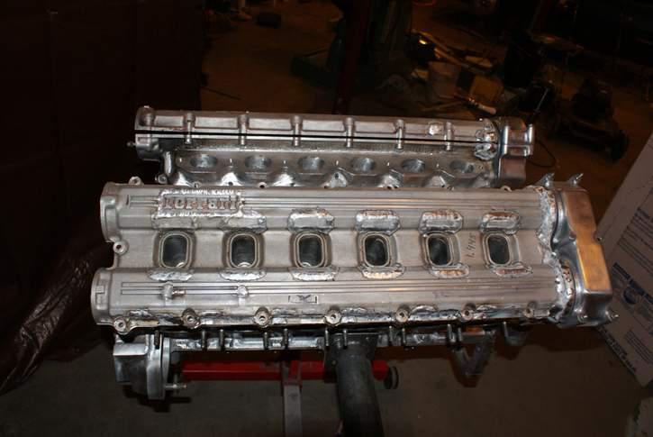
How did you get the "Ferrari" script logos on TR valve covers?
BrianA said:How did you get the "Ferrari" script logos on TR valve covers?
I cut them out of the 400i intake manifolds then cut a matching hole in the TR cover and welded them in. If you look close you can see I didn't spend as much time cleaning up the sandcast finish in between the letter as I probably should have...someday
edit: Note that I also filled the little holes that the plug wire clips went into on the TR....they didn't seem to make any sense for this application
![]()

![]()


759NRNG said:I second this .....I truly have nothing to offer in way of 'constructive criticism', but what I sense is this is nothing more than an engine, regardless of the lineage that you are fortunate enough to have the time, knowledge/skills,and the facilities to execute....so therefore onward and upward......excellent work maestro!
Thanks, that is exactly what I was going for. The goal was to make it look like it could have come this way. The block was available in 84, the heads were available in 84, and factory is known to let prototypes or 1 offs sneak out the door.
mekilljoydammit said:I have to say though that you've inspired me to go digging into the enginelab stuff and holy cow that solves some problems I had.
Well come on over and jump in....if nothing else a second set of eyes on what I've written or alternatives you've written would be great!
Here's how I solved the bent engine stand issue....I welded 2 together I had to cut the top off and reweld it straight, they point up a little so they didn't point at eachother. Then a couple pieces of pipe and its a stand. It had to be wide enough to allow the trans.


I got this valve in the mail one day...and someday I hope to have a project I can use it on but it was bigger than the 86mm bore so no go for the V12....

I found blanks that were intended as oversize gsxr1300 valves at kibblewhite and made thos work instead. First is cut to lenght using a carbide endmill then polish the end, I made a little block to hold it square.


Then do it 47 more times. I sped up the process by cutting most of the metal off using the chop saw....I figured if a sawzall was good enough for the castings then a chop saw was good enough for valves :)


Then keeper grooves. I ground a carbide form tool for this job.


These valve use a 5mm stem, the TR uses 7mm. New guided required. The exhaust guide wants to be mostly like the ferrari but with the 5mm bore and machined for the gsxr stem seal and lower spring retainer

The intake needs to be that plus be 2mm oversize. To increase the valve to valve spacing by 2mm I had to move the valves 1mm, but that's a radius number so 2mm over on the diameter

Then make them...its not like the OD tolerance is +/- 0.0002 and my lathe is 70+ years old and badly worn.....I had to leave the OD about 0.001 over and sand them to final size..sand, mic, repeat....then make 47 more


mke said:mekilljoydammit said:I have to say though that you've inspired me to go digging into the enginelab stuff and holy cow that solves some problems I had.
Well come on over and jump in....if nothing else a second set of eyes on what I've written or alternatives you've written would be great!
Got the console program and am digging in... I think I'm getting the general principles but need to mess with the simulator, and for that matter at some point get hardware, a test engine, and my dyno going. Do you know if the more open EL framework can be put on the lower end Infinity ECUs? For my first few applications I don't need H-bridge drivers, for example.
One of the big things I want to do is stuff like closed loop upshift rev matching. A code variant of one of the Subaru ECUs did this, where it knew gear ratios and spark cut to try to match engine RPM to what the next upshift would be. Also rotary ignition, though in the grand scheme of things that's not that hard. Over time I have some weird antilag algorithms I wanted to try to make work but that really requires getting my dyno going.
mekilljoydammit said:Got the console program and am digging in... I think I'm getting the general principles but need to mess with the simulator, and for that matter at some point get hardware, a test engine, and my dyno going. Do you know if the more open EL framework can be put on the lower end Infinity ECUs? For my first few applications I don't need H-bridge drivers, for example.
One of the big things I want to do is stuff like closed loop upshift rev matching. A code variant of one of the Subaru ECUs did this, where it knew gear ratios and spark cut to try to match engine RPM to what the next upshift would be. Also rotary ignition, though in the grand scheme of things that's not that hard. Over time I have some weird antilag algorithms I wanted to try to make work but that really requires getting my dyno going.
I am running infinity HW, but I'm not still they will still "upgrade" you for free, you'd need to shot them an email and ask. The firmware is serial number keyed to the HW so need to have that, then give them the # and they add you to the FW...or buy EL HW
Remember EL comes with control NO model of any kind, you need to create you for everything....or just use mine since it done and I think working. As you say, the features you are talking about are not hard, the shift one is probably not more than 10 or maybe 15 lines with most being ratio inputs and stuff like that...maybe just and if/else with a rev limiter set points for each gear so 5 math items (if its a 5spd)...or the other way around with the if/else to feed the gear selected to the math item.... Either way, easy.
The rotary would be handled in the engine description item....have a look at that and if you don't think it will currently do what you need they are very willing to add additional functionality. They've added a few things I requested.
You'll need to log in to post.


