


Nice work on cage. I would tie rear axle points also to the cage, for example what i did on audi 80. Keep up the good work!


Nice work on cage. I would tie rear axle points also to the cage, for example what i did on audi 80. Keep up the good work!

In reply to Ervinr :
It was considered, but we haven't seen any signs of cracking or deformation at the subframe mounts on the L2wd car so decided to leave it up to the factory sheet metal for now. The moment anything looks like it's fatiguing, reinforcements will be added, but for now I'm trying to keep things as light as reasonably possible.
Seam sealed the tunnel overlap, and the slots in the floor which were cut open to drop the seat bars further. Sealer is annoying to try to apply nicely, but not as annoying as dust and water and stuff coming into the car all the time:

Buncha stuff this weekend. Finished up some welding on the rear subframe, making it solid mounted with a big trailing arm drop:

Welded up a diff skidplate:


And some control arm reinforcements:


Then assembled all that onto the car with some Superpro bushings in the upper and lower control arms for a little give, and adjustable heim joint trailing and toe arms:

Next, something completely different:

We masked and painted the front blackout section first; hotrodders have it right, there's nothing that looks quite as nice as some brand new flat black:

Then masked that off and did the rest:
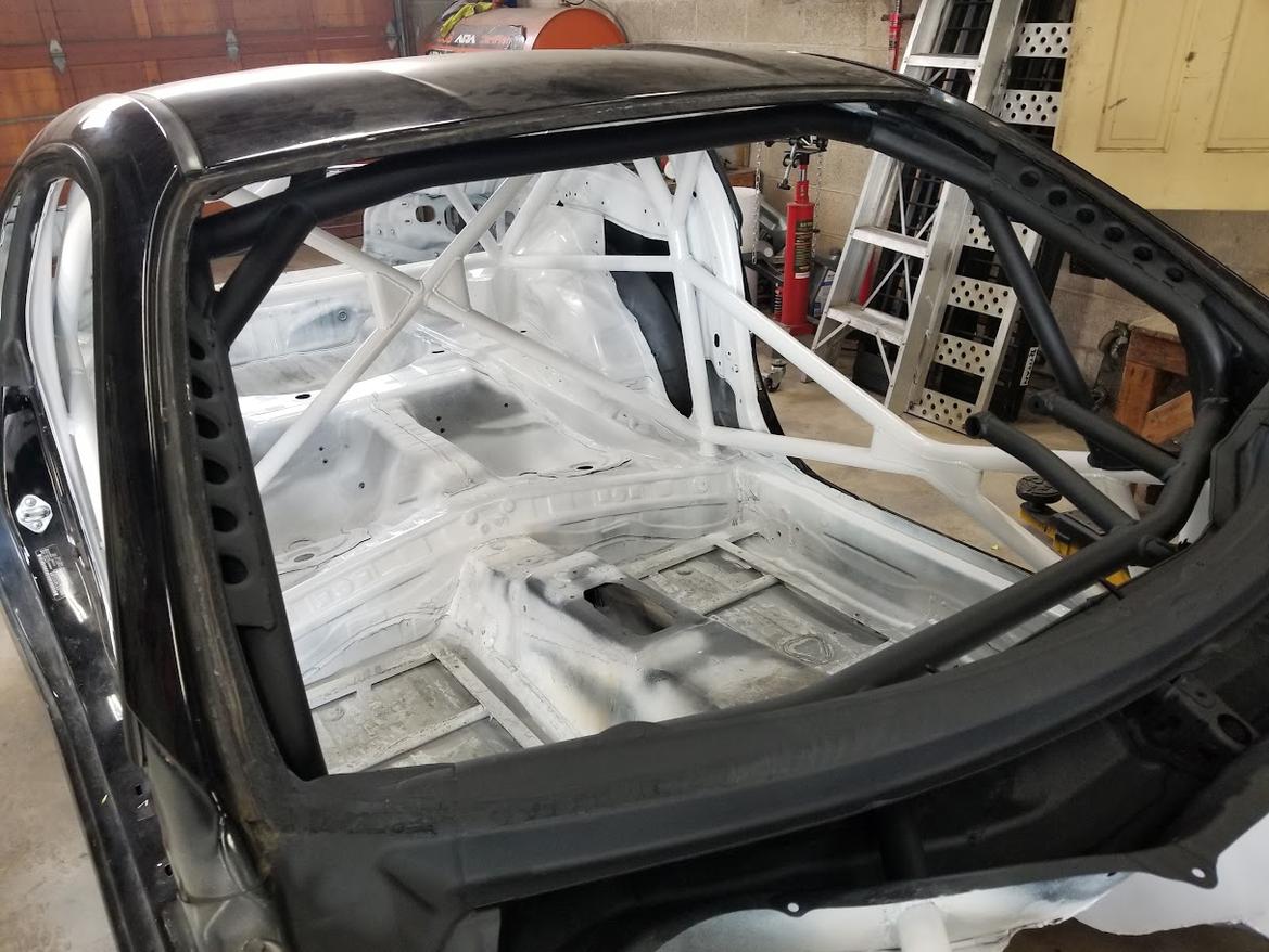


The floor and tunnel remain unpainted for now since I'm planning to do more stuff there, but it'll be good to stop worrying about surface rust on the cage. I won't get to work on this thing next weekend so this was a good opportunity where the paint can sit and harden up for 10 days or so before I go clanging around in there again.

Love the blackout section. Great thinking.
In reply to AxeHealey :
It's really a huge improvement in both visibility and eye strain in any sort of weird light conditions- I definitely recommend it for any race car, along with blacking out any shiny stuff on the dash.
I'd like to get some thoughts down on the rear suspension research thus far, because I was stewing on it for the past couple days. Here's why:
Initially, I scanned and did some messing around in SolidWorks and determined that lowering the trailing arm mounting points on the subframe would help, both with the obvious antisquat geometry and also the bumpsteer- I did scan a full subframe, but mathed and designed around the passenger side because I know that's the easiest place to work on the thing when it's on the lift. Then, I zapped together a subframe with a 30mm lower trailing arm pickup point and measured that throughout the travel on the car- and it was great! A little trailing arm length tweaking got me near-zero bumpsteer across all 10" of travel, as measured on the passenger side. I never checked the driver's side.
Then I welded up what should be the ideal trailing arm drop, a full 60mm lower than stock, welded the toe eccentrics in place in their innermost position, and assembled that all onto the car. The only bushings are in the upper and lower control arm, the trailing arm and toe arm are both adjustable with spherical bearings at both ends. This also proved to work well and get me that sweet zero bumpsteer setup, once the trailing arm length was dialed in. Here it is mid-measuring, again on the passenger side:
And the magic trailing arm length was then measured, and transferred to the driver's side:

Then, finally, for the first time in this whole process I measured the toe curve on the driver's side and this is where things got weird. With the same exact toe and trailing arm lengths, and no other adjustments available, it was significantly different- my lengthened trailing arm was making things toe out under compression, and yes, shortening it did get things back into range but, what was going on here?
My first assumption was that I'd welded my trailing arm tabs on unevenly, but after taking every measurement I could think of across various diagonals and longitudinals, they appear to be fine. So is every other tab location on most of the links... but the driver's upper balljoint is about 1/8" further forward than the one on the passenger side. I measured, and remeasured, and pointed the laser up at the bottom of the car and measured again, and it seems to be consistent. All the spare control arms I have are perfect copies/mirrors of each other when laid on a flat surface too. So, WTF?
TLDR:
I've had a suspicion for a long time, just from eyeballing the suspension on the L2wd car, that BRZ rear subframes are not entirely symmetrical, and it looks like I've just confirmed that they're not, but not by much. The L2wd car visibly has more camber and toe on the driver's rear than the passenger's at full droop, and it appears that the reason is that the tabs for the upper control arm mounts are ever so slightly different side to side- a whopping .065" inboard and an incline difference of about 1deg on the axis of the two bushings when compared side to side, according to my scan.
I think in the normal 5" of travel these cars have, it's completely unnoticeable in terms of suspension settings, but when you stretch that to 10", things get silly. My first attempt is going to be to get the ideal trailing arm length, which will be shorter, set on the driver side and transfer that to the passenger side and see how far off it is- I don't mind a bit of tweaking from there, as long as all the lengths are within 1/4" or so I bet I won't be able to feel any differences from the seat.
Barring that, I may try to "correct" the location of one of the driver side upper control arm pivots, since I know I can get a really good toe curve with the passenger side geometry. But, all this stuff moves around on bushings so I'm skeptical of the idea that this small a change is worth chasing, even though I can obviously detect it when measuring the bumpsteer. I'd just slot the mounting holes, adjust, and weld a washer on when I've got it where I want it. If it comes to that, here's a visual of how tiny the difference at that 10mm mounting hole is:

That seems like too fine an adjustment to chase, but we'll see. It does seem consistent across subframes, at least- I think the robot that welds the tabs to this stamping is probably pretty repeatable.

Hooray for mass production tolerances!

Any chance the knuckles are not identical? You could scan them, then mirror one of the models and superimpose them to find differences.
In reply to Shavarsh :
Could check, but they're identical at least to the point that the tape measure can tell. Plus if the knuckles are different, I'm definitely not making my own of those! Well, unless I decide to change the whole rear suspension entirely anyway.

Even if the difference is the upright and not the subframe, it's a consistent difference, right?
Alright, back to that suspension conundrum. I set up the laser on the DS rear again and got to work:
After a bunch of cycling the suspension and checking the bumpsteer every inch or so, the entire 11-11.375" range seems viable, with no more than 1/16" of bumpsteer anywhere throughout the full travel. Copying the length over to the other side gets similar results, although interestingly that slight difference in upper control arm locations seems to produce a little more toe change right in the midrange on the driver's side, and cram it more into one end of the travel or the other on the passenger's. I think my plan will be to initially set these around here, maybe a bit shorter to be on the safe side and avoid unintentional toe out, and then slowly reduce the length if the car feels unstable at all- shorter lengths will bring more toe-in under compression, which is what the stock geometry has LOTS of, so I know how that behaves and it'll be nice being able to fine tune it. Overall I'm quite happy with where I've ended up here, even if there's a little variation side to side.
Next, I took the springs off for a bumpstop height check. This was too low for proper diff clearance in the rear, front seems great:

So, I changed the shock extenders on the Bilsteins back there- these are my "spare" shocks so getting the overall length dialed in here will let me correctly spec the much more expensive Ohlins I'm planning on later:


This worked great, and the rear will hit bumpstop slightly after the front, but not so late that the diff is already getting friendly with rocks:

That length change does change things a bit for the full droop end of the bumpsteer, since there's more droop now, but I really don't think 1/8" of toe here or there at the absolute extreme of droop is going to do much (for reference, the L2wd car has 1/2" of toe out at full droop). Maybe it'll be noticeable on jump landings, who knows, testing required.
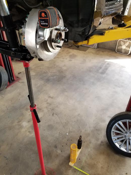
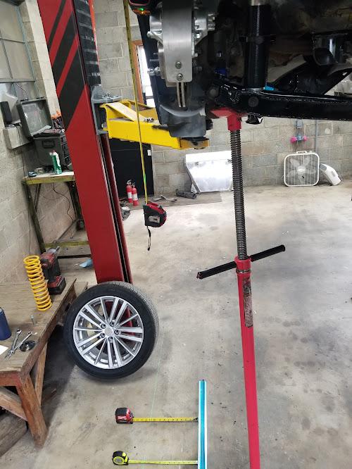
On a different aspect of this project- I decided to try out OSH Cut for some pinstands. Having the tubes laser cut reduces the amount of time I have to spend trying to grind and notch things perfectly, although their flat sheet cutting is more expensive than sendcutsend and the edges on all the tubes needed deburring:

The bottoms of the stands are round tube so they can self-rotate to match the pin angles, and the solid steel pins are welded in at a 5deg angle to hopefully keep things more settled than fully perpendicular stands. The little U channel in the middle is a tray for lug nuts or other hardware if needed. They feel a little wonky on the concrete floor, which I know isn't perfectly flat, but they're sure not coming out of the holes with the car on them and will hopefully do great in a grass/gravel service park which is what they're really for:

They are right at the limits of my harbor freight jacks so I'll probably make a slightly extended pad for it, there's nothing more annoying than running out of travel trying to get the car on the stands in a short service.
A little paint finished those off:

And speaking of paint, if you don't need to sneak the foam brushes in between the body and the cage a few places after spraying, does your cage even fit the chassis tightly enough? Did some of that which is all pretty much invisible anyway:

And reinstalled the steering column support, which is a dark but still slightly contrasting color so it remains obvious that it can be removed:


¯\_(ツ)_/¯ said:
What color and brand paint did you use on the steering column? I'm color blind so it's hard to tell with the one picture. From what I can see so far though, I like it and think it would go well as my interior paint on the 914. I've been trying to find something to contrast with the ratty blue but also a little character. Dark silver or charcoal with some flake was high on my list.
Also loving the progress. I'm curious how different your twins will be with all of the changes betwixt them.
In reply to captainawesome :
It's one of the Krylon Fusion Hammered finishes- I think Dark Bronze, but will have to double check that. It looks dark grey with a little metallic in it, the metallic was very dependent on spray angle so if you're using it somewhere it'll be obvious definitely keep that in mind when spraying- this will be pretty hidden when assembled so I wasn't too worried about it.
In reply to ¯\_(ツ)_/¯ :
Good to know. I used a gold version of that paint on the k swapped FRS valve cover and loved it. I'm worried with the amount of coverage I need, that a brush or roll on would make more sense, but I may try the spray anyway.
Sara's seat arrived! This Sabelt X-Pad actually fits me pretty well too, but the halo is a little low so I still like my Daytona more- it works for her so into the car it goes:

These OMP 36-hole brackets really do have the best options for mounting that I've worked with, they just always require a little trimming to actually fit a given seat. Still much better than not having enough usable holes, like most seat brackets.

And, the upper oil pan arrived courtesy of some very skilled CNC friends- this thing is SO nice, I wish I could just get everything machined because it looks a whole lot better than my welded stuff:


Bolted up, you can see the oil line ports in the last photo coming out of the front:

And the view from underneath:

So next I needed to weld up the part that bolts to that:

The ridiculous amount of welding (cover passes, grinding to find holes, sometimes more cover passes) was because I wasn't sure I could weld watertight- but I apparently did:
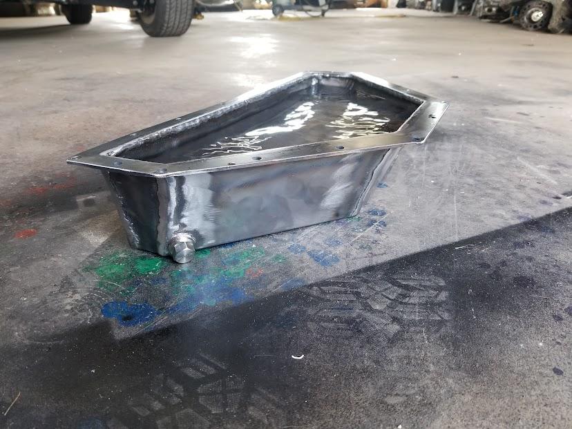
Tipping it every which way it seems to be solid. The baffle pattern I came up with isn't exactly advanced, but I think it should keep things from sloshing away from the (still to-be-made) pickup and do a good job reinforcing the pan if it takes a hit. The pickup will be in that back section, which is also where the oil from the crankcase will spill into. I didn't want to put any fancy flappy doors in for fear that a rock could break stuff like that.

I painted it flat black in the hope that it would be much easier to detect leaks on a matte finish, and bolted it up- yes, the flange warped during welding, but I don't think threebond/yamabond/right stuff/etc cares that much anyway:

And I also couldn't resist a marketplace ad and snagged some of my favorite wheels for it- these are 17x8 so they'll be the tarmac setup:

System won't let me upvote ![]()
That upper pan is a thing of beauty!
You'll need to log in to post.


