
Another build and once again it isn't a car. This one is going to take a while too. I'm reasonably certain it's going to piss me off at least once and get shoved on the shelf.
This time it's a steam engine. A PM Research Model #1 Drilling Engine.
The finished product will hopefully look something like this.

It has a 1" bore, 1 1/2" stroke. It is double acting and single cylinder.
As it comes out of the box. Some assembly is required. 

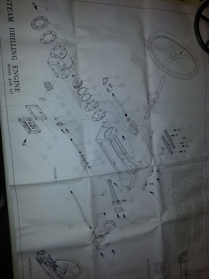
The kit comes with the above castings and three pages of plans. One page showing a over all, the other two giving dimensions.
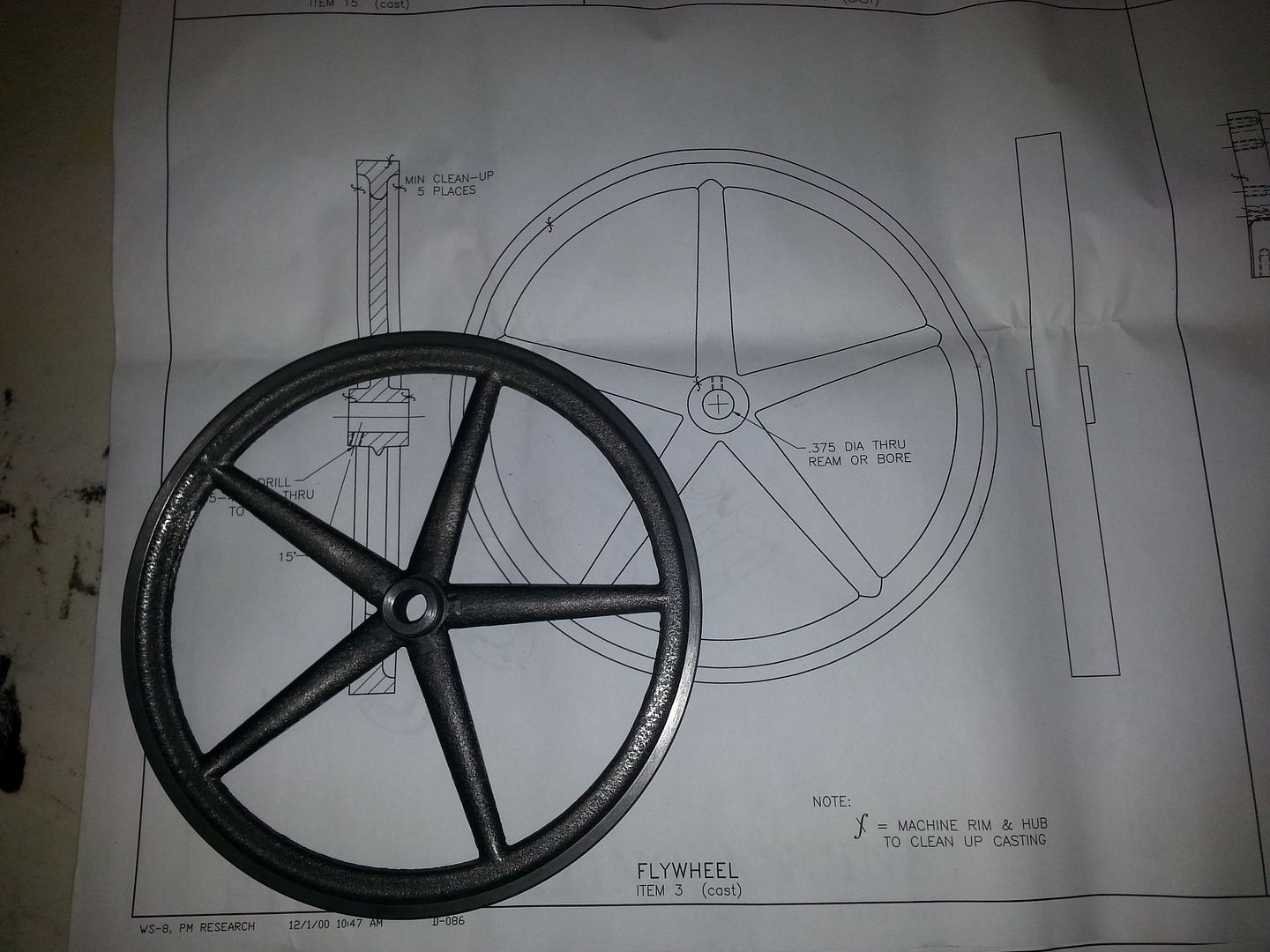
I started with the flywheel because it's pretty easy and I haven't turned anything in over a year. The only thing that has to be accurate is the bore diameter and since it's done with a reamer being accurate is a no brainier. Chuck it up once and turn everything and bore the center.
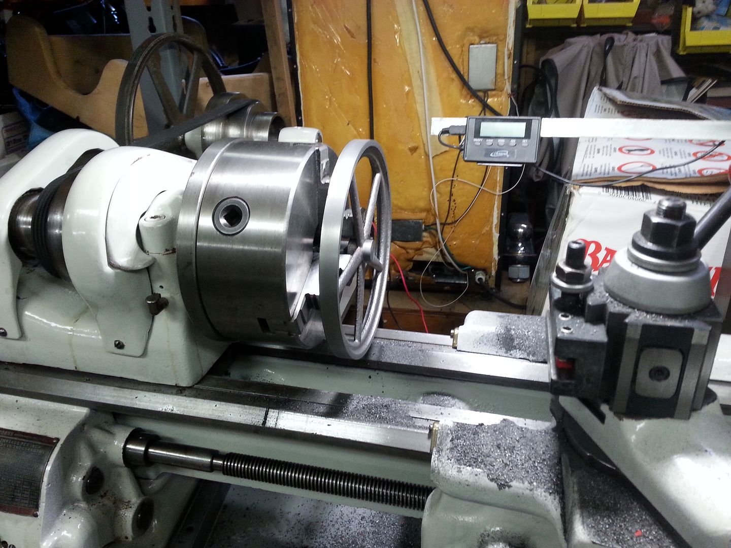
And done.
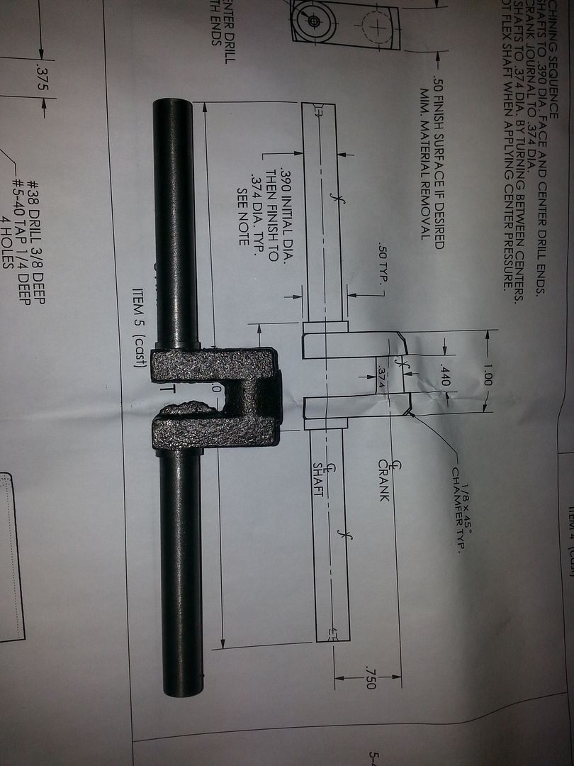
With the flywheel done, I moved onto the crankshaft. I cleaned one side and then flipped it to turn the other side to .400. Then I flipped it again to turn the other side to .400.
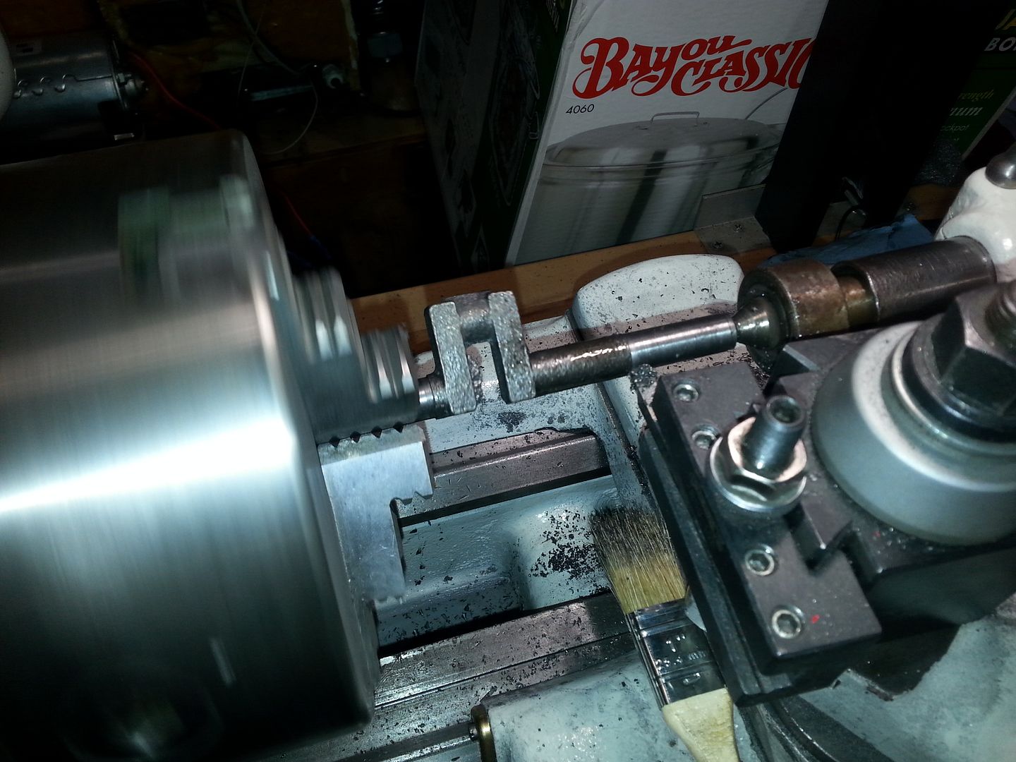
And a good start. I still need to turn it to .391. Then I need to build the jig to turn the crank throw.
Here is one running.
http://www.youtube.com/watch?v=1De2R7Qa3RM
Way cool, I've always wanted to build a steam engine. I'll be watching with great interest.

I did a little more work on it yesterday.
Started working on the base. I got it set up on the mill and machined the base flat.
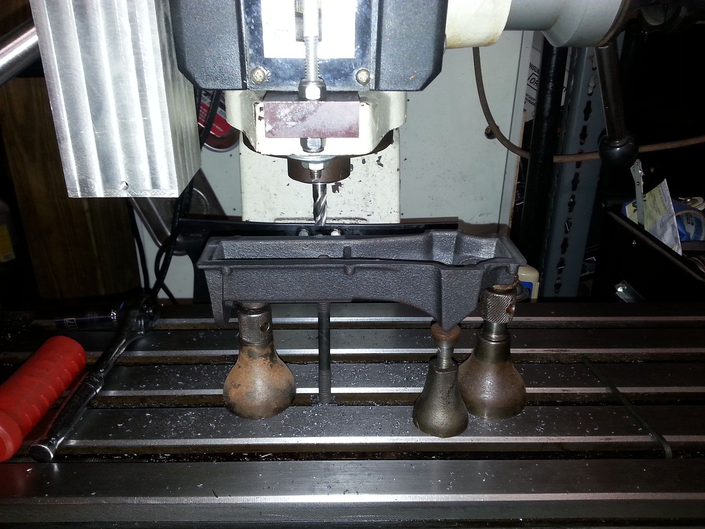
The next step on the base is machining the cylinder mount flat. There I ran into a problem. I don't have a large 90 degree plate to mount it to. I'll have to order one.
So I moved onto the cylinder.
I decided to reference everything off the bore. The meant turning the bore first. so I chucked it up in the lathe. I got out my antique boring bar and bored the cylinder.
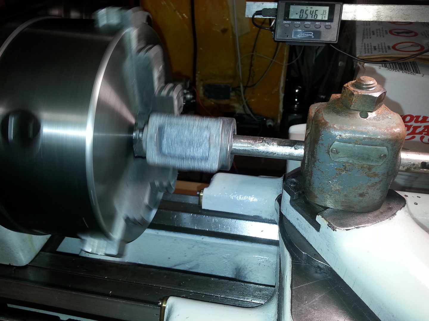
Finished size on it is 1.001. The target was 1.000. Close enough. While it was chucked up, I also finished the face on one side cylinder.

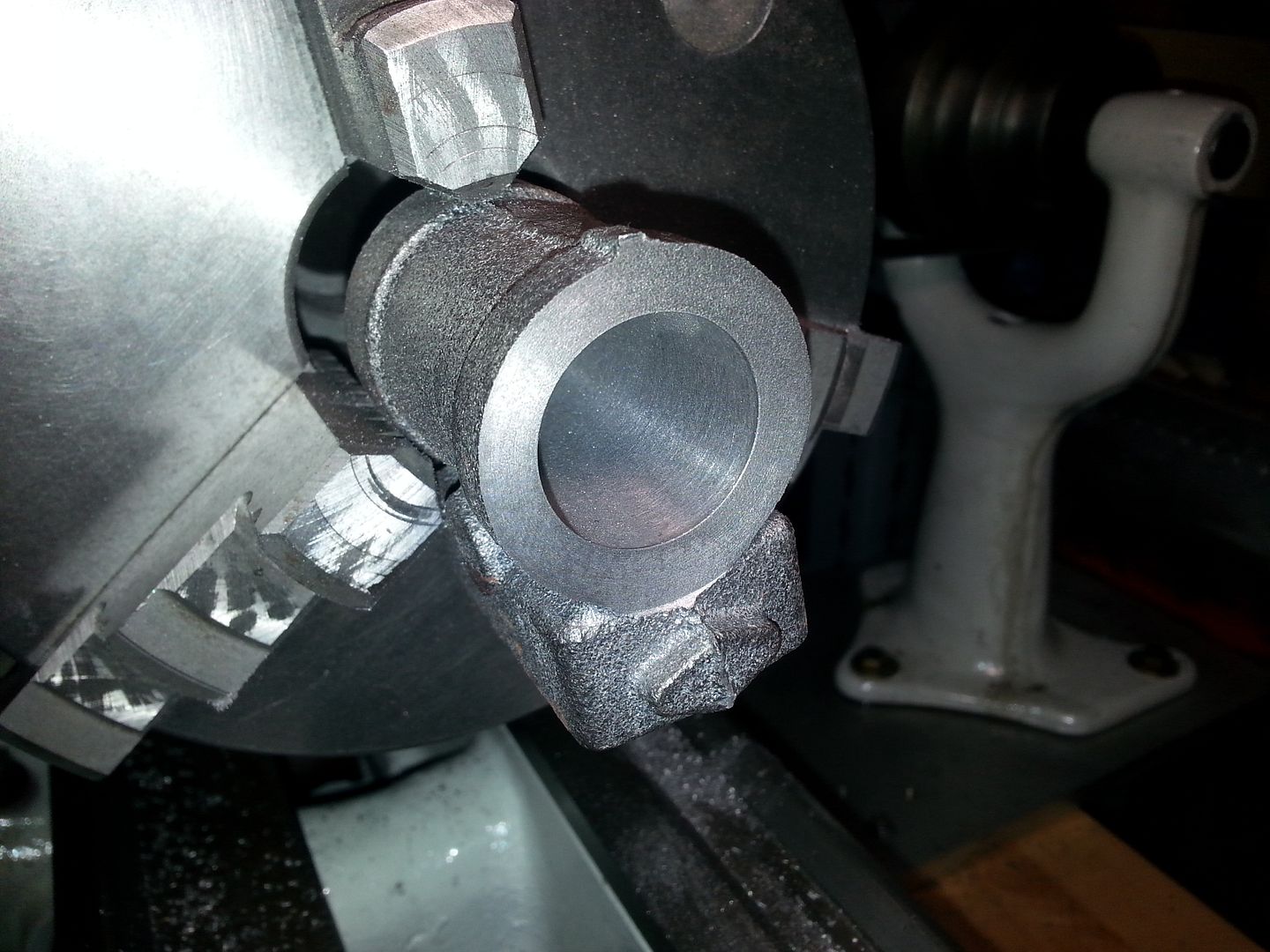
The next problem was going to be facing the other side of the cylinder. I also needed some way to hold it when it moved over to the mill for machining of the steam chest. I made a mandrel out of a piece of 1" aluminum rod. I slide it into the bore with some thread locker to hold it. I should be able to heat the cylinder and slide it back off when I am done.
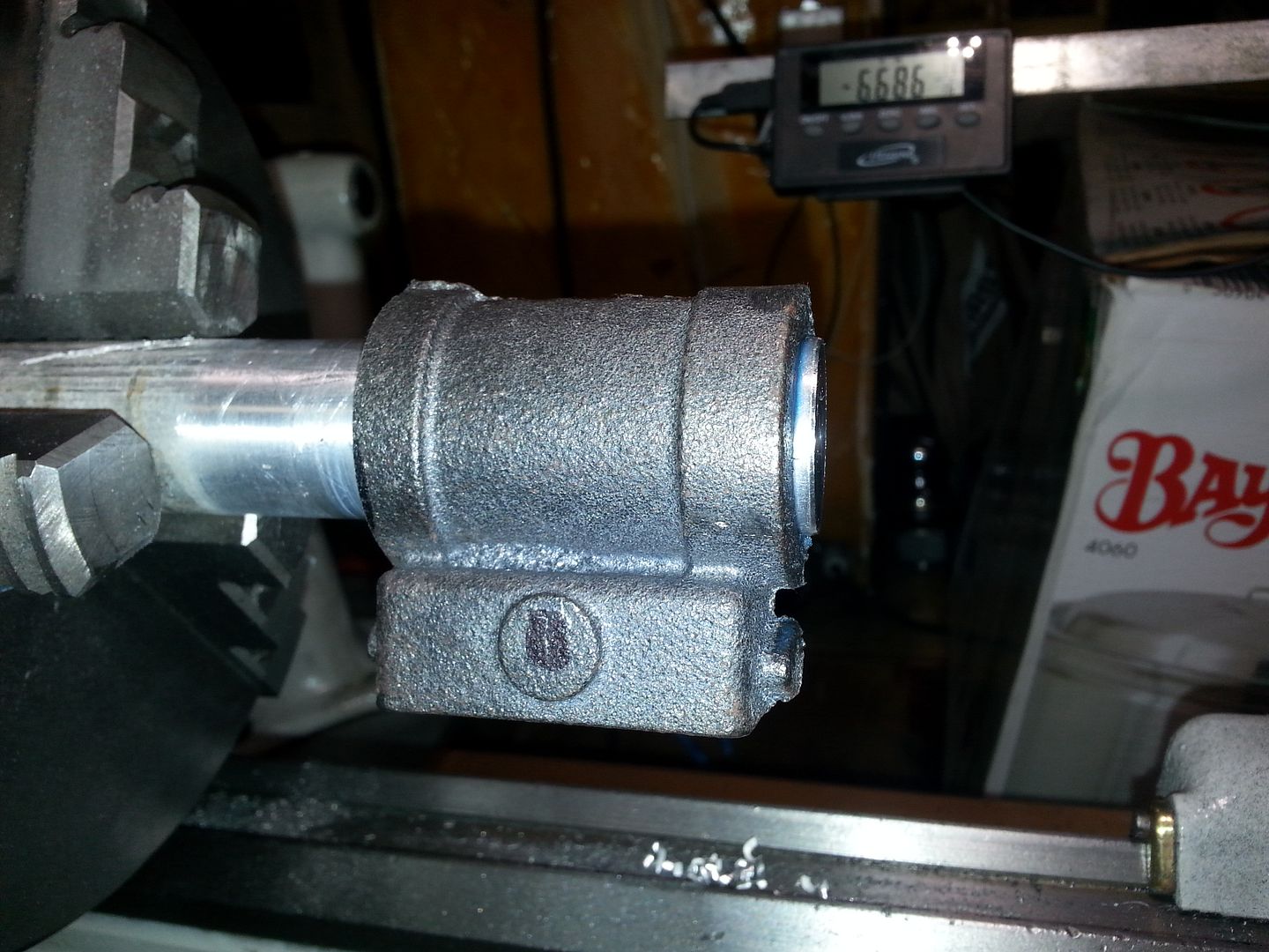
That done, I machined the other face.
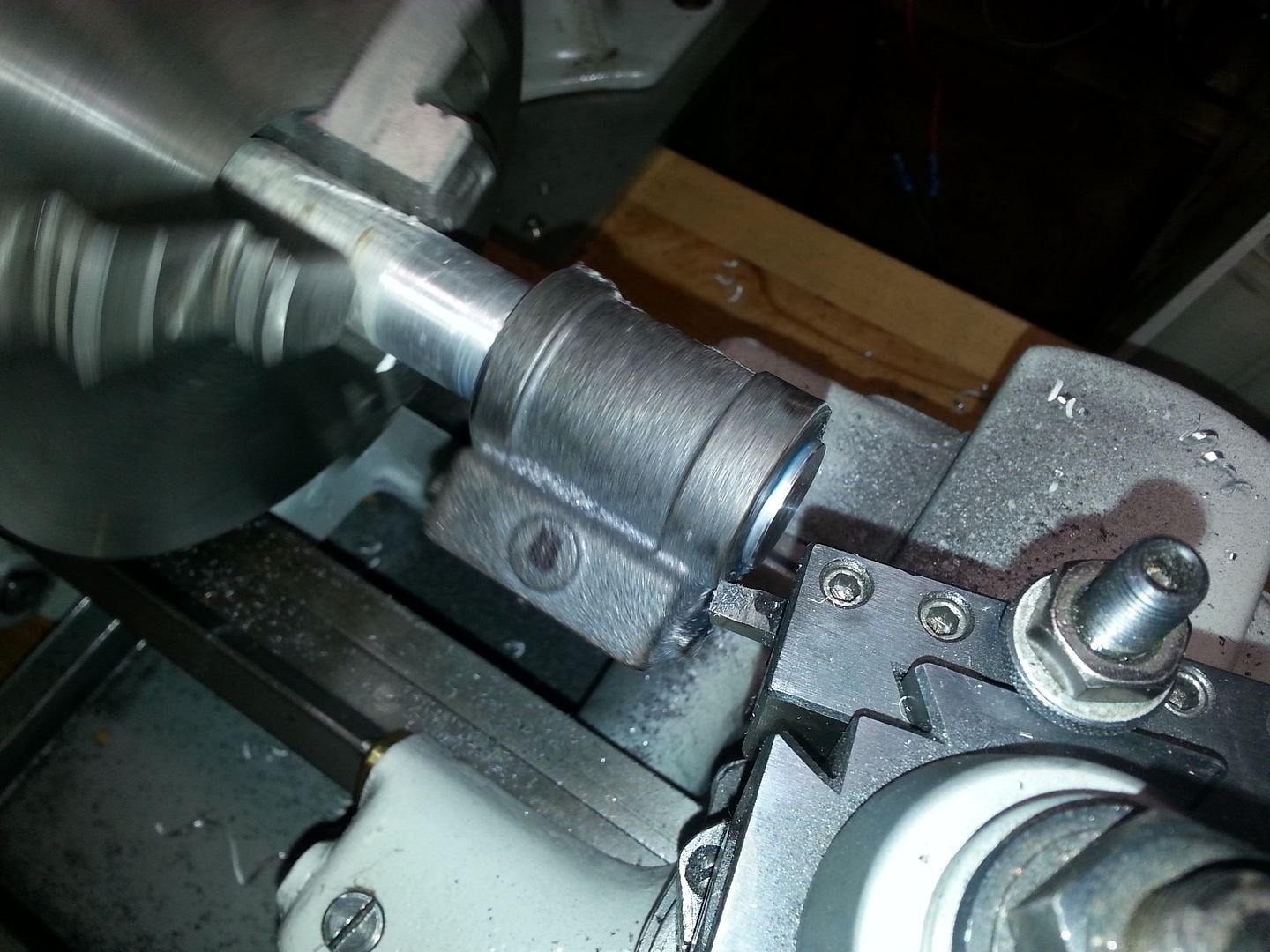
That's as far as I made it. More to come.
A little more done early this morning before everyone got up.
I started machining the steam chest.
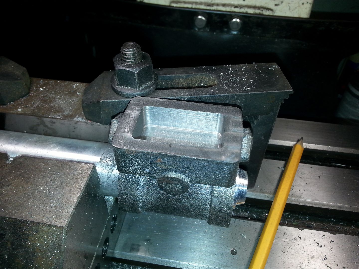
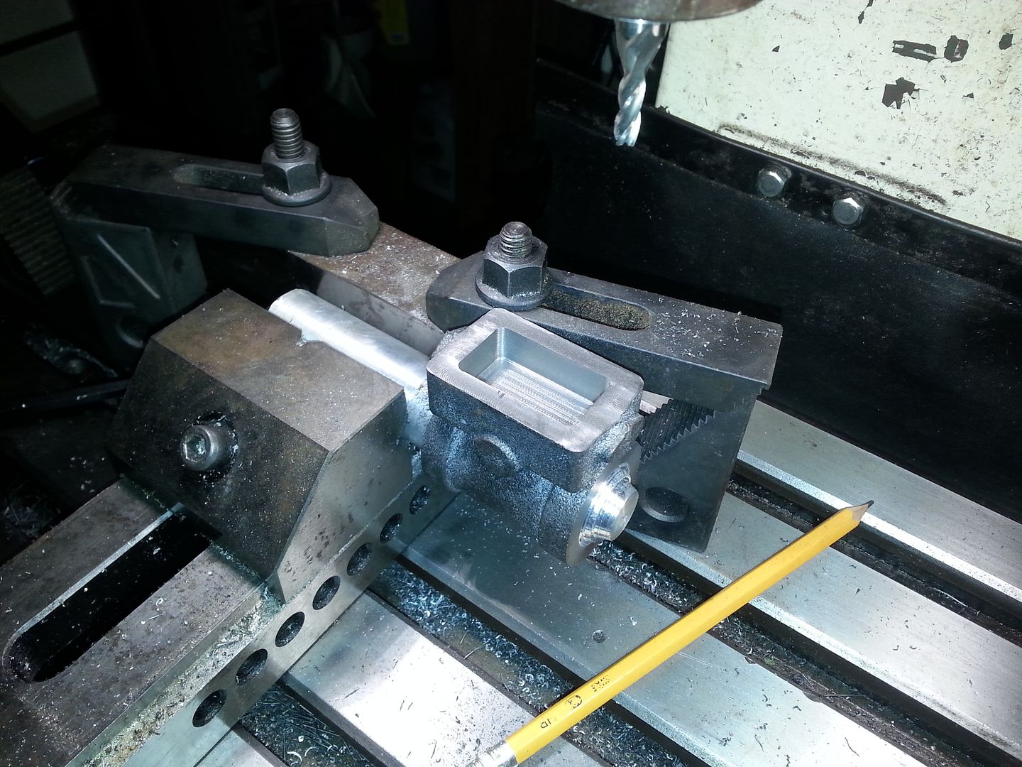
There is still more to do on this, but today was family day.
More to come.

RossD
PowerDork
9/3/13 10:09 a.m.
How are you going to machine the center of the crank?
I love this. I work with steam as part of my job. I need something like this for my office...
Edit: What about a boiler? Homemade?
I want to hear more about steam-cocks, Johnson-bars, and blowing down.
In reply to RossD:
Ross, I have to make one of these.

It's a mandrel that holds the crank so the throw is centered on the lathe.
I need to order a piece of aluminum to make it out of.
I did some more work on the steam chest this afternoon. There were three slots to cut for intake and exhaust steam passages and the steam chest had to be cut to the finished depth.
I screwed up the center steam port. I tried to make the cut at full depth and the bit flexed a good bit. Hopefully it won't be too much of an issue. I'm used to being limited by the power of the machine, not the strength of the cutters. 
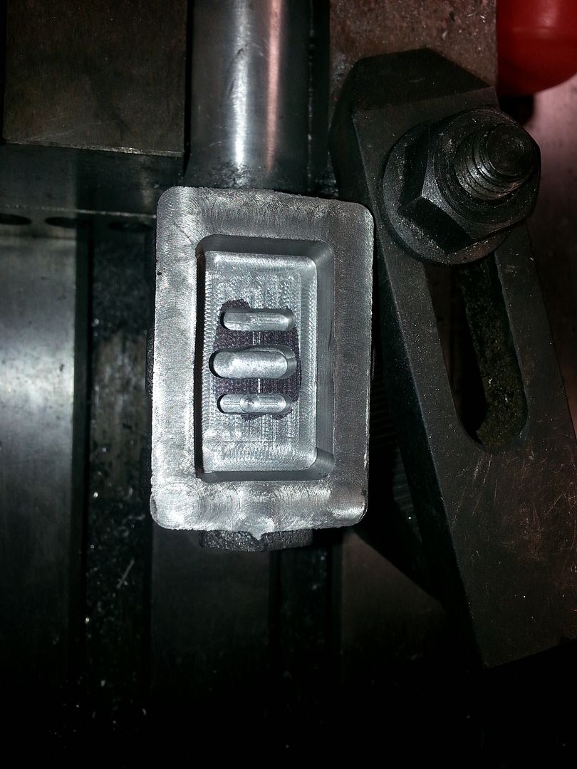
More done.
Inboard cylinder head. I started by turning the cylinder side to size.
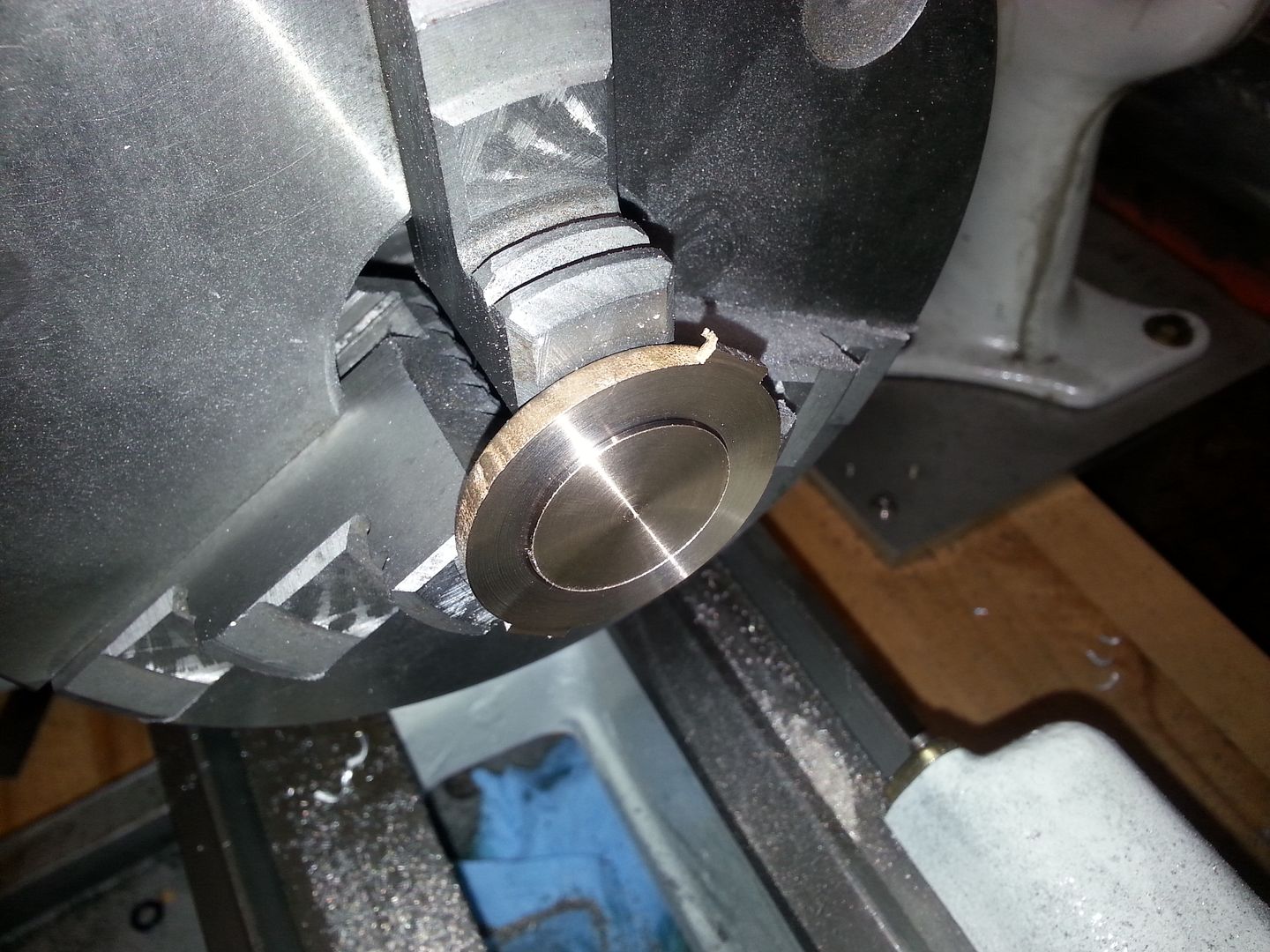
Then on to the other side, except for one problem. The finished thickness of this is about 1/32 of an inch. Once again, no way to hold it in the lathe, without a mandrel. So I made one out of a piece of scrap cast iron.
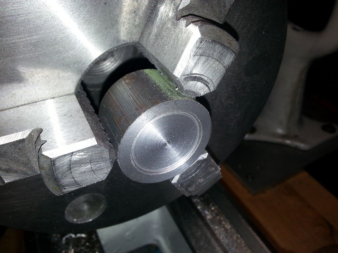
Using thread locker, I glued the parts together and turned the other side of the head.
Crappy picture.
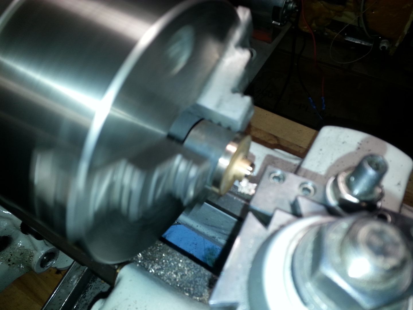
Then I turned the outboard head. It was pretty straight forward.
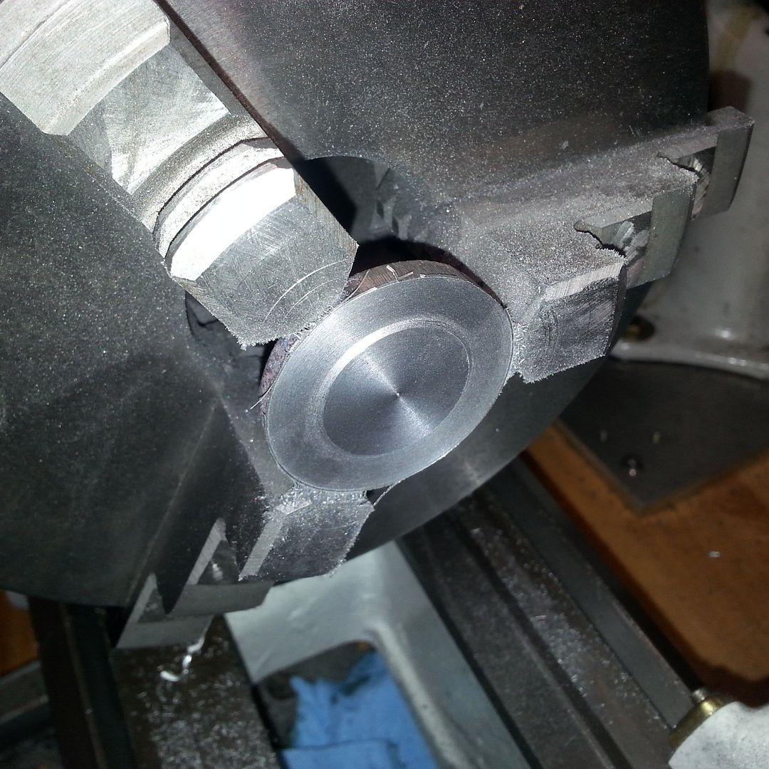
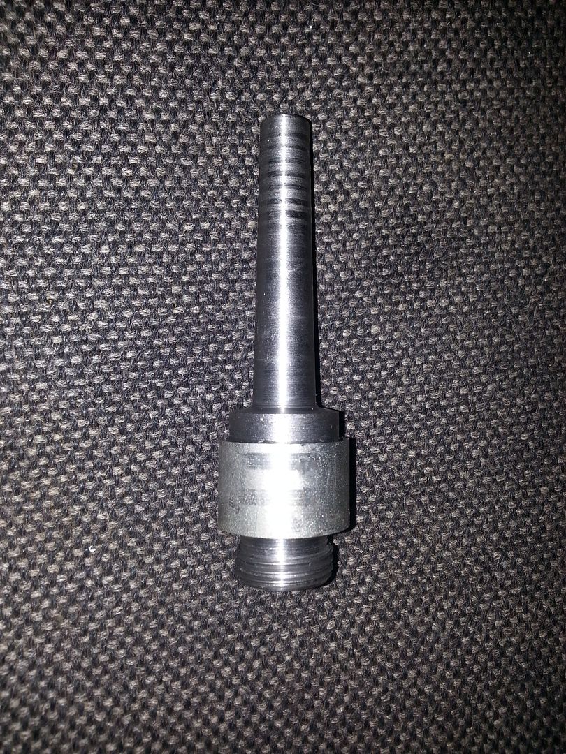
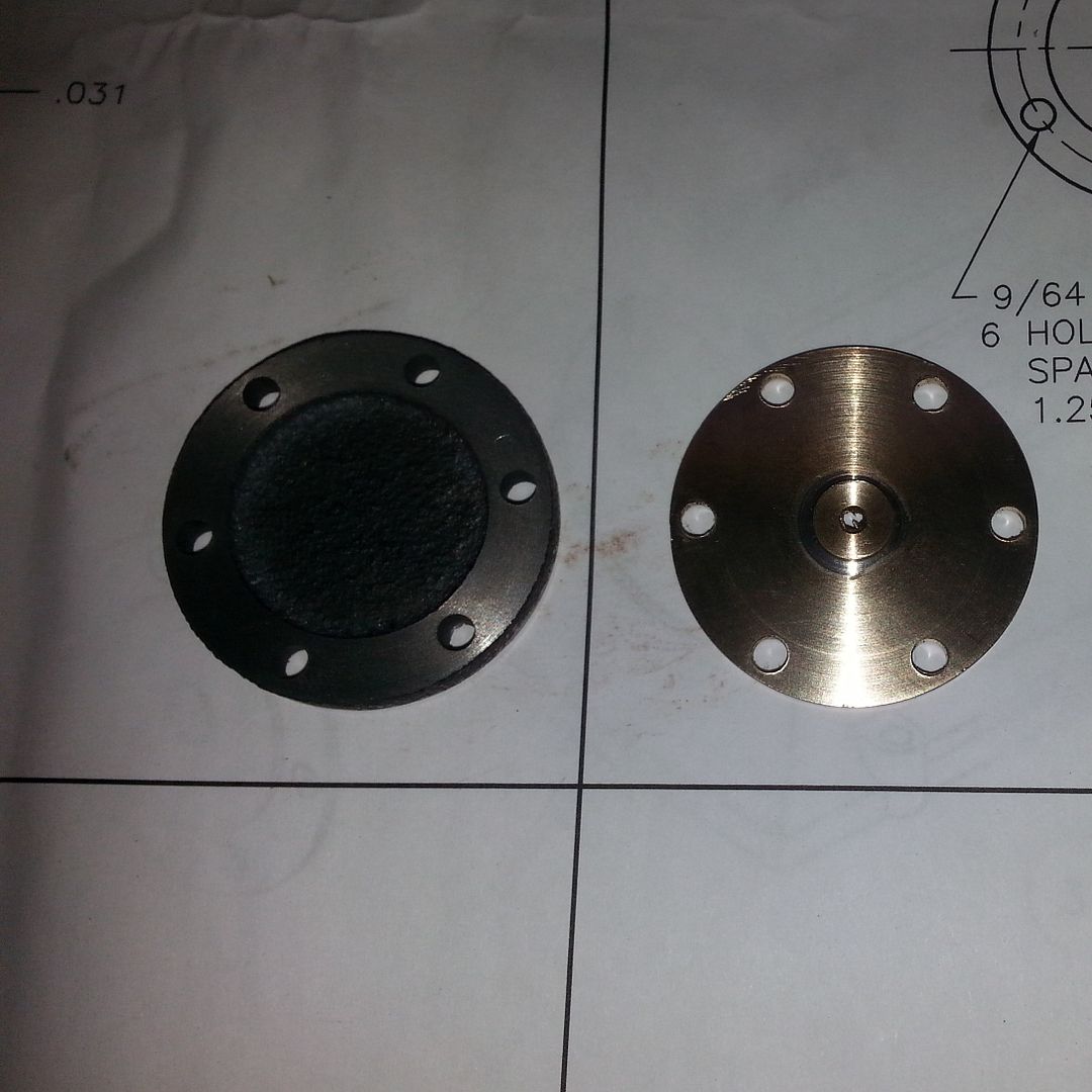
Now I needed to drill the six holes for the head bolts. I have a rotary table, but no easy way to hold the heads centered on the table. I also have a 3", 3 jaw chuck. It would be easy to use it to hold the heads, but I would still need to center it on the table. The table has a #0 morse taper center hole, so I needed an adapter to go from the morse taper to the 3/4-16 thread in the back of the chuck. They are $40 online and being a cheap bastard, with all this machinery sitting around, I made one. I started with a piece of 7/8 shaft left over from the golf cart project and ended up with this:
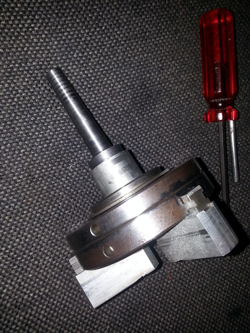
That let me mount the 3 jaw chuck, centered, on the rotary table to drill the cylinder heads.
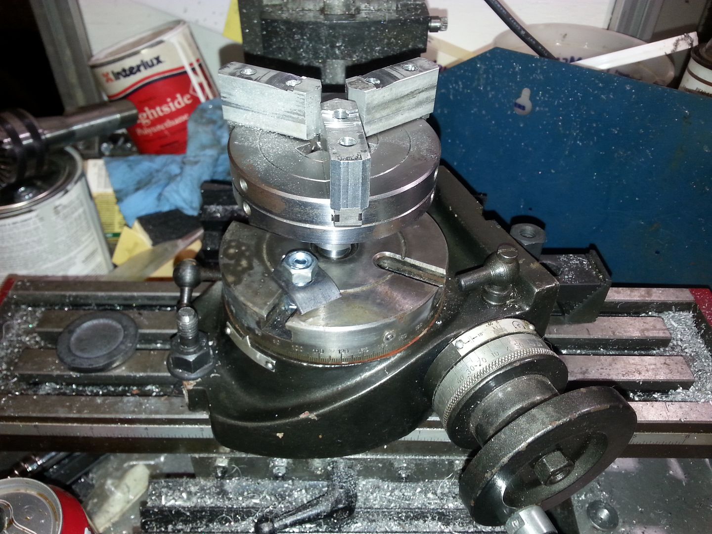
And presto, 6 evenly spaced holes in both heads. I'm a happy boy. 
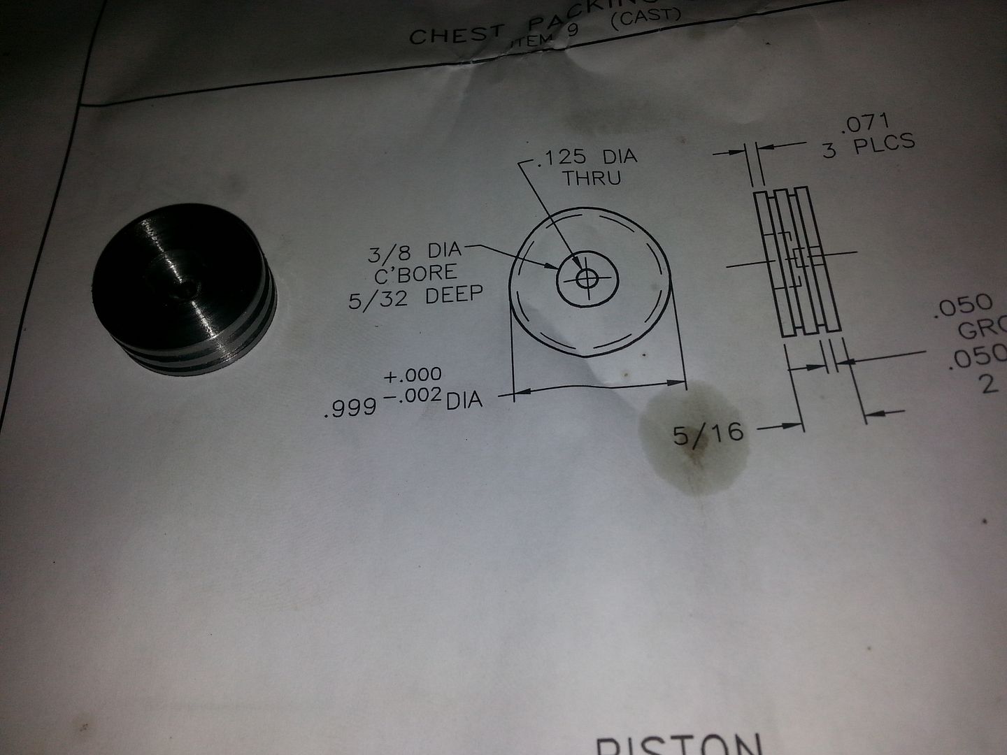
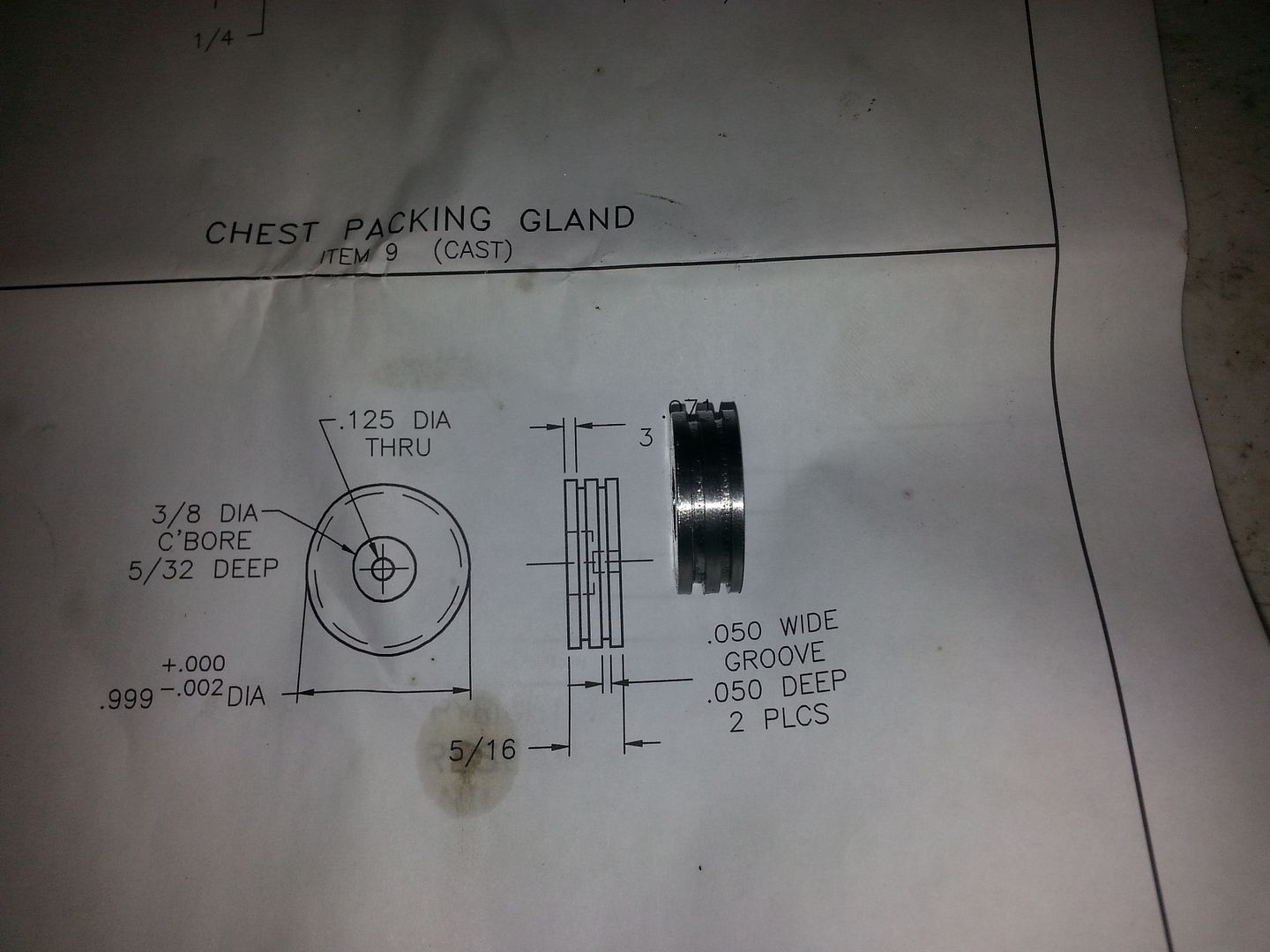
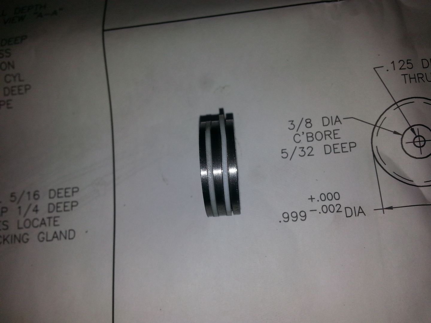
Next step was the piston. Starting with a piece of 1 3/8 CRS I turned the diameter and then using a modified cutoff tool, cut the ring grooves. The rings are Teflon.
Impressive....  Keep going...

Caleb
Reader
9/7/13 8:40 p.m.
So you bought a kit that requires you to do all the machining?
In reply to Caleb:
Yes. I bought a set of castings, hardware and plans. All the machine work is on me.
The little red engine in some of the pictures I built out of a machined kit.
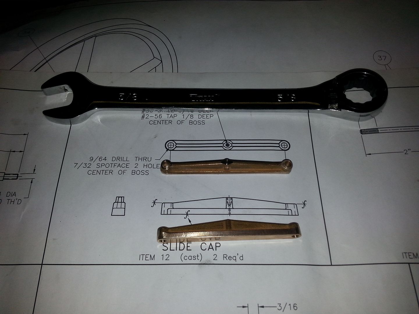
I machined these this morning. That's all so far today.
In reply to Toyman01:
Hi, great work, thanks for posting.

![]()


