I need some help. I'm trying to get a 5V square wave RPM signal to turn into a 12V square wave signal for a digital dash I'm putting in a Formula SAE car. I know I've seen people smarter than me pull this off with Megasquirt setups, but I can't seem to find any resources that explain in simple terms how to figure out what circuit I need to make.
Any help would be appreciated. I'd love to get this dash working for a test day tomorrow and Autocross Sunday.
This isn't really a megasquirt guru issue - you need a basic transistor inverter supplied by a 12v source ("amplifying" the 5v signal).
EDIT: Google NPN common emitter circuit
Oh, OK. I just threw that out there as it's the only place I've seen this used. I'll start reading up on those... the electrical engineers on our team haven't been much help.
Is the ignition triggered by a hall sensor? If so instead of feeding the hall sensor 5V can you feed it 12V and get a 12V square wave?
Nah, it's a COP. Here's the car I'm working on:

It's got a Yamaha WR250.
Looks like a NPN common emitter is exactly what I need. Looks like I'm making a trip to Radio Shack.
Nope, unfortunately not. Although I feel like if we're hitting cones with the nosecone, it's time for a driver change.
Alright, it's not working. Tell me what I did wrong.
Here's the diagram I used.

Here's what I wired up-
Vin is the 5V square wave (verified that it's indeed 5V with an oscilliscope)
V+ is 12V constant
Vout is the (theoretical) 12V square wave output
Rc is three resistors in series that measured to 11.6kOhm
Re is a 4.6kOhm (measured) resistor that goes to ground.
Vout is coming out as a 12V constant, not a square wave. What did I hook up wrong?
You need a forward bias - when the square wave drops to zero the transistor falls to it's inactive state. Add a 2.3v DC source to the 5v square wave to make it oscillate between 2.3 and 7.3.
EDIT: Google voltage divider network ![]()
Before I go digging too far, you sure you've got things hooked up to the right pins on that transistor? BTDT.
Giant Purple Snorklewacker wrote: You need a forward bias - when the square wave drops to zero the transistor falls to it's inactive state. Add a 2.3v DC source to the 5v square wave to make it oscillate between 2.3 and 7.3. EDIT: Google voltage divider network
Okay, that makes sense. I'll have to try that. I wire up a voltage divider for a thermistor for the water temps on this thing.
And yeah, I'm fairly confident I'm more likely to have a fundamental flaw rather than a wiring issue at this point. ![]()
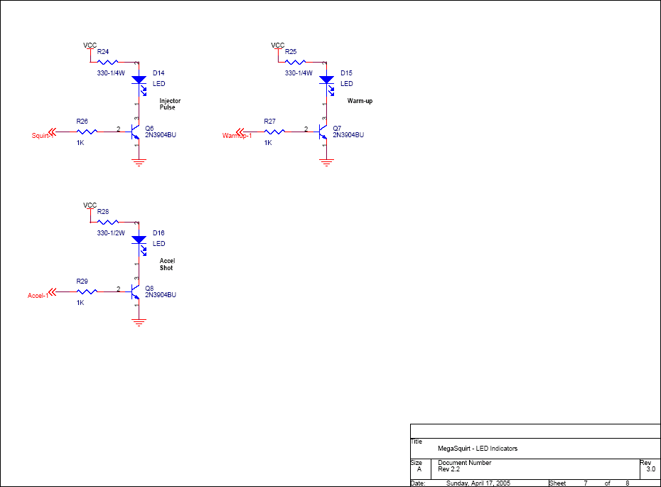
Look at the wiring diagram for the front panel LED's. I think that's about what you want. I can't find my schematics here, but I think you want the emitter grounded and a bias resistor on the base. But then, I learned on tubes and these newfangled transistors always did confuse me.
Yeah, look at the megamanual, or what I have on my drive as MegaSquirt V3 Main Board.doc. Dunno how it is on teh net. Anyway, about the last page, labled as "injector pulse", "warm-up" and "accel shot". All the same circuit. +12v to 330 ohm resistor to your signal point to the collector. Signal in to a 1K resistor to the base. Emitter grounded.
Giant Purple Snorklewacker wrote: You need a forward bias - when the square wave drops to zero the transistor falls to it's inactive state. Add a 2.3v DC source to the 5v square wave to make it oscillate between 2.3 and 7.3. EDIT: Google voltage divider network
I'm sorry for such a fundamental question... but how? I've got the 2.5V voltage source, how do I add it to the square wave? Just simply wiring them together doesn't work.
Just tried 12V to 12kOhm to Signal out to Collector, Signal in to 4.6kOhm to Base, and Emitter grounded. No dice. Same configuration as what Dr. Hess recommended from the Megamanual, but with different resistor values. Should I try that same configuration with different resistor values, maybe 330 and 1k like he used?
Hotlinked fer ya, Ag.

You leave the diode out of the circuit and attach your "signal out" between the 330 ohm resistor and the collector, where the diode was. Or, leave the diode in the circuit and you can watch it blink. Take your out signal at the non-banded (+) end.
Finally got it working, and then the Dash2 died. Seriously. I was in the middle of changing some filtering settings, and it just froze and refused to respond. Reflashing the firmware would always result in a "connection error" and fail.
Never buy a Race Technology product. Seriously. This dash has never successfully been used since we bought it in 2007.
You'll need to log in to post.