And not the usual one.
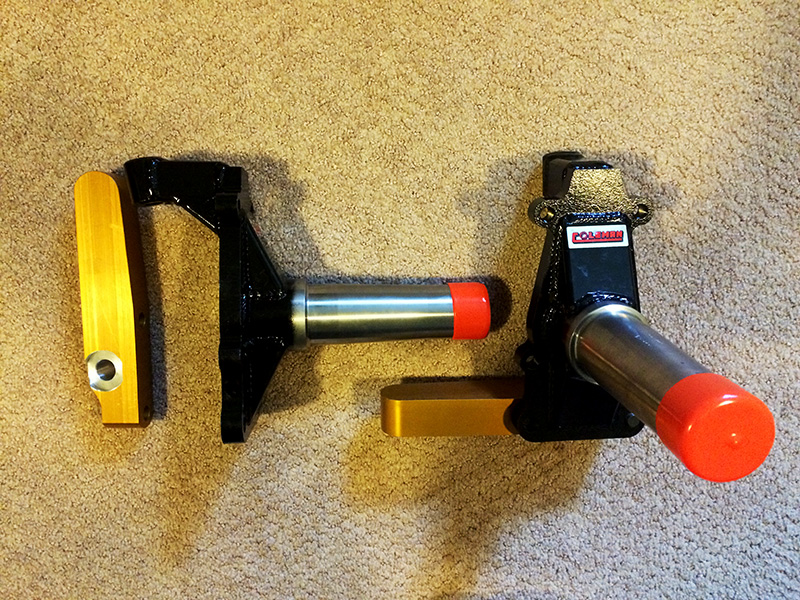
So I'm working on setting up the steering on my C-Prepared project (https://grassrootsmotorsports.com/forum/build-projects-and-project-cars/1981-camaro-c-prepared-build/59501/page12/). One of my more recent purchases was new spindles with blank steering arms.

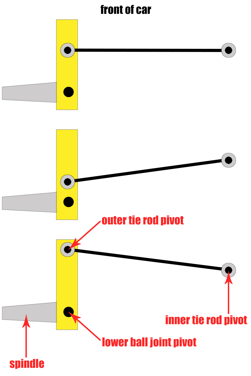
The thing I'm struggling with is how the tie rods should be angle, when viewed from above. In other words, what impact the fore-aft location of the outer tie rod will have on geometry and handling.
I made a quick sketch (not to scale) to illustrate what I'm talking about.

My initial feeling was that the tie rods should be as straight as possible (top image), but some are telling me that may not be the case.
What sort of impact (all other things left constant) could I expect from moving ONLY the outer tie rod end fore or aft?
Thanks!
That would affect your ackerman geometry and of course your steering ratio and max. lock angle. Drift guys move their pivots inward (closer to the steering axis) for more lock, but they also move the rack (or tie rods, with a special bracket) the same distance to preserve ackerman.
In short: If you're happy with your steering, leave it the same as stock.
Good point on leaving it near stock. The rub is I have no clue what stock was. Those bits are long gone.
Your "Camaro" is very heavily modified...is the stock steering rack mounting location still there? If not, you'll have to throw stock measurements out the window and start from scratch, just as if you were building a custom car.
GameboyRMH wrote:
Your "Camaro" is very heavily modified...is the stock steering rack mounting location still there? If not, you'll have to throw stock measurements out the window and start from scratch, just as if you were building a custom car.
I'm using the stock steering geometry (faster box, but same drag link steering with a stock center link), so the location of the drag link, inner tie rods, etc, are all in the same location as stock.
OK well in that case you're best off finding out what the stock location was and just copying that.
Gimpy, is the steering box faster than stock? (IIRC you will be powering it too?)
I am the one whispering in his ear that its a complex problem with many variables (to be optimized, because race car).
It is a faster, power steering box.
Yeah you might be able to get a little improvement by using a non-stock location, but it's a lot of work and you'll need to fabricate some parts to do it right.
I'd say if you have a faster box, you've already got your improvement though 

A good starting point for rack fore-aft location is to determine how far your outer TRE needs placed(as this will ultimately affect how much turning angle you can get/steering effort/speed, work backwards based on max travel of the rack itself).
From there, with your knuckles straight, measure how far ahead of the ball joint centerline that the outer TRE is at. Say 6in.
Now turn full left or right(you want to check turning on the inside, as because of Ackerman you should steer tighter on the inside wheel). Now how far ahead of the ball joint is the TRE located? Remember just on the fore-aft axis. Say it's 4.25in.
So I'd start by putting the rack about 5.125" in front of the ball joint, or 7/8" behind outer tie rod holes when steered straight.
This will keep the rack closest to 1:1 input throughout the range of travel. Making it further back will increase the rate of angle gain near eds of travel on inside wheel(more Ackerman).
Google Ackerman, because at rest those other tie rod ends need placed correctly to start it off right.
As far as rack height in relation to the knuckles, you want the tie rods from inner to outer joints to be the same length and angle as your lower control arms. Possibly change up or down depending on how much camber gain your arms produce to keep bump steer at a minimum.
Exit: go fiddle with a 1/10 or 1/8 scale RC car or buggy. Most of my experience is off-road and preventing bump steer over large wheel travel range. Racing 1/8 scale buggies the Ackerman adjustment(basically moving inner tie rod forward or back on the swing set linkage) made a big change in handling, mostly high speed stability and twitchiness in tight turns from one track to another.
Just thought of a good improvement you might be able to make: If you've changed the track width with different-offset wheels, you could change the ackerman angle to match.
Why not do three separate holes so you can try different setups for different conditiond? Maybe three oval holes with slugs for minute adjustment and the seperate ovals for gross adjustment? Or am I way overthinking the benifits of adjustable here?
Multiple holes don't make any sense unless you want to accomodate a bunch of wildly different steering setups.
If you wanted to switch between drift and race setups for example, and you could move the rest of the steering linkages to suit, multiple holes could make sense there.


