I'm trying to figure out how to position a trigger wheel for a VR sensor onto a crank. What I need to know is how to position the gap (I'll call it the "TDC gap") that corresponds to TDC at the crank: is this TDC gap positioned exactly centered with respect to TDC or is it positioned at exactly the trailing or leading edge?
In the diagram below, look at version A:

For this application, I know from the specification that the first tooth counter-clockwise from the -2 gap indicates 117 degrees BTDC. Each tooth and gap is 3 degrees and I've got the trailing edge of the tooth at 117 degrees BTDC. What I don't know is whether I would need to rotate the wheel counter-clockwise an additional 1.5 degrees so that the sensor is exactly over the tooth (and the TDC Gap exactly centered at TDC).
I don't know much about VR sensors but I'm guessing that the sensor should be positioned at the trailing edge of the tooth because I assume that the entire tooth must pass the sensor in order to create a complete sine wave. Once it gets to the ECU, I assume it's converted to a square wave...
Thanks...
What application is this for? Is it a stock set / ecu or an aftermarket ECU?
Much more details are needed in order to answer your quesiton OR at least so we can go reasurch it.

Ok did some searching and I think this is the answer. (Ya I can not resist a challenge)
Table 9.1. Trigger Settings
Trigger settings
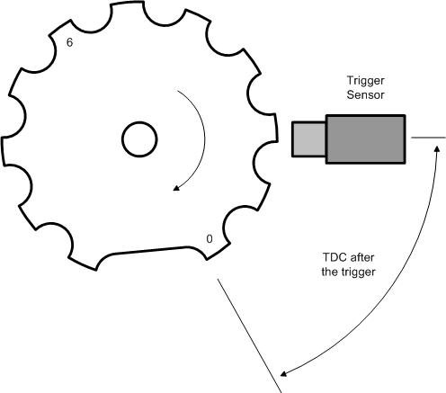
TDC after the trigger
It is very important that the 'TDC after the trigger' value is configured correctly. The value of 'TDC after the trigger' must be between 40 and 60 degrees. Before attempting to configure it the two values 'Trigger tooth' and 'Next trigger tooth' must be determined and configured properly, unless a coil-type trigger wheel is used.
In the example shown in Figure 9.6, “TDC after the trigger, 12-1 trigger wheel example” 'Trigger tooth' is set to 0 and 'Next trigger tooth' is 6.

I got this from Here >>>http://www.vems.hu/manual/html/ch09.html<<<
It looks like you measure from the leading edge of eh first tooth the sensor encounters ofter the missing tooth (that is 0 or tdc) and the sensor is mounted to aligh with the leading edge of the tooth you want to to mathc the degress of offset you want. I also notied in some of my reading that if you go over 100 deg you will probibly ahve to put in a offset to "calibrate" the ECU so you have the ability to get enough advance.
Thanks for the info.
The wheel is from a mid-'90s Saab Trionic system, which handles fuel, timing, and boost, and has in-cylinder knock detection via ion-sensing. It's been hacked and there's tuning freeware, so, for my earlier Saab, it's like having an aftermarket ECU that runs well out of the box. (People have installed it on non-Saabs, too.)
Anyway, I want to install it on my '86 900. All I know is what the manual says: "There are 2 ribs missing after the 58th one. When rib 1 then passes the sensor, the control module knows that the crankshaft is 117 deg. before top dead centre (BTDC)."
As you can see, it's not possible to tell how the wheel is supposed to align with respect to TDC but it looks like it should be rotated to the edge.


