So I think I'm on the right track. My plan is to drill the outer tie rod attachment points as close to that 2" mark as possible, leaving room for bumpsteer adjustment. Looks like my drill press will get to take a trip to PA.
I am using the same program with my build and it looks to me like your Ackerman error is very small. You can eliminate it with just a little toe out adjustment
loosecannon wrote: I am using the same program with my build and it looks to me like your Ackerman error is very small. You can eliminate it with just a little toe out adjustment
Thanks! That's what I was suspecting, but I think some of my measurements might be a little off. I'm going to put the car on some turn plates this weekend and verify before i drill any holes in my steering arms.
So because I'm not 100% sure on my math in the software, I started to make a quick set of turn plates. The plan is to mount each bottom plate to a piece of plywood, grease in-between with some petroleum jelly, and cut the pivot nail flush so I don't go through tires so quickly. This should be an easy way to do some testing and make sure I have my ackerman correct.
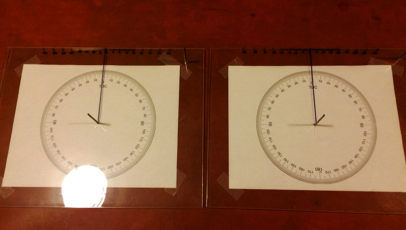
The plan for testing is to not drill the steering arms right away. Instead, I'm going to use a c-clamp to hold the outer tie rod to the steering arm and carefully turn things. The clamps will let me move the tie rods forward and back easily so I can quickly see any difference in ackerman. It might make more sense when I snap some pictures.
I have been trusting the Performance Trends software, just double check all your measurements and you should be good. The program shows ideal Ackerman for your wheelbase and shows your actual Ackerman based on your steering geometry measurements, the difference between the two is your error.
loosecannon wrote: I have been trusting the Performance Trends software, just double check all your measurements and you should be good. The program shows ideal Ackerman for your wheelbase and shows your actual Ackerman based on your steering geometry measurements, the difference between the two is your error.
I will be taking the laptop with me when I go visit the car. Right now I think I have errors in my measurements for steering, as the software binds way too quickly.
Well, the turn plates were a bust, but I'll get to that in a minute.
Went back up to visit the car and started by getting the new idler (from last time) and my new, V8 pitman arm installed on the car.
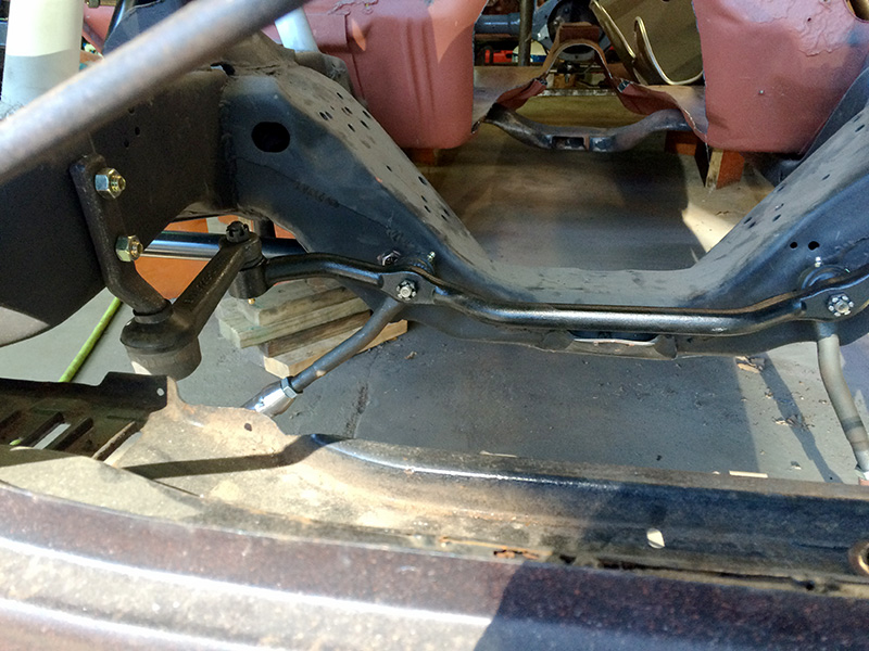
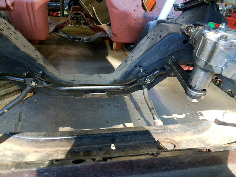
This immediately solved the previous issue with the center link being off kilter.
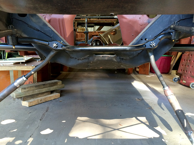
So, why didn't the turn plates work? Simple. My brilliant idea to "temporarily" attach the outer tie rod to the steering arm to test various placements wasn't quite up to the task.
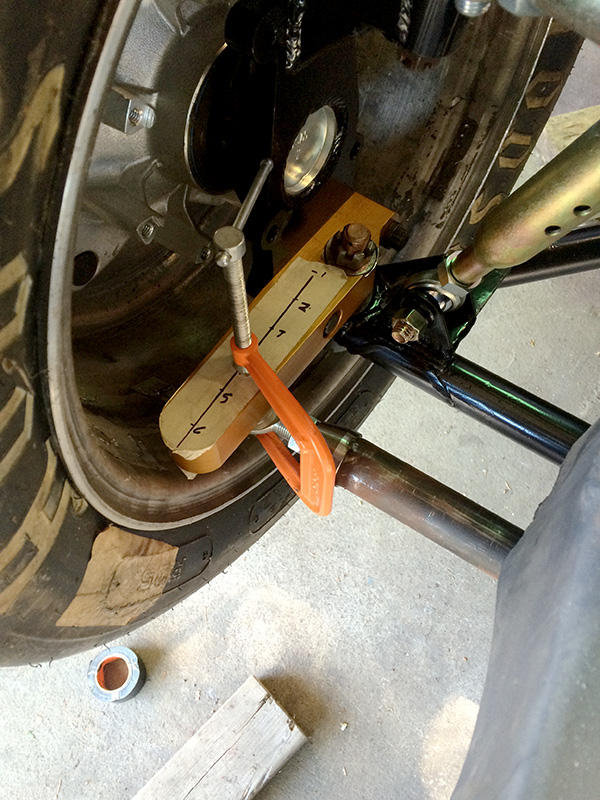
The clamps just weren't able to hold onto the steering arm with the weight of the car on the suspension, even with my well lubed turn plates. So sadly, that was a bust.
Instead, I just jacked the car up into the air to at least see what things looked like. The coilover simulators I have allow me to keep the geometry at ride height, even when in the air. From just looking at things, it does seem like I have some ackerman.
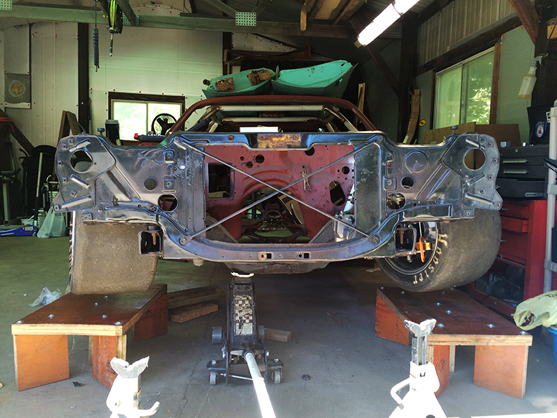
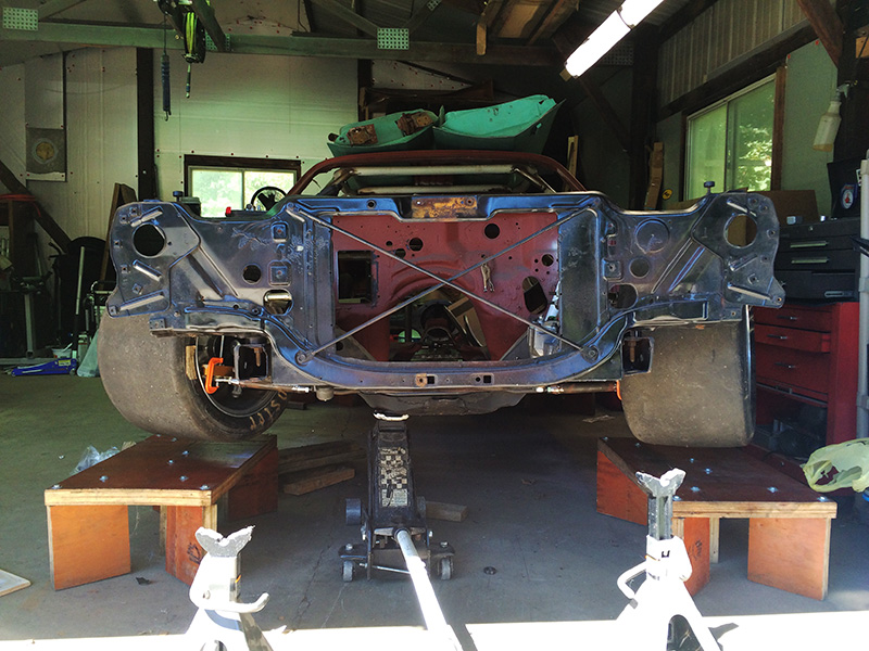
Looking good, right? Well, from above it doesn't seem as good.
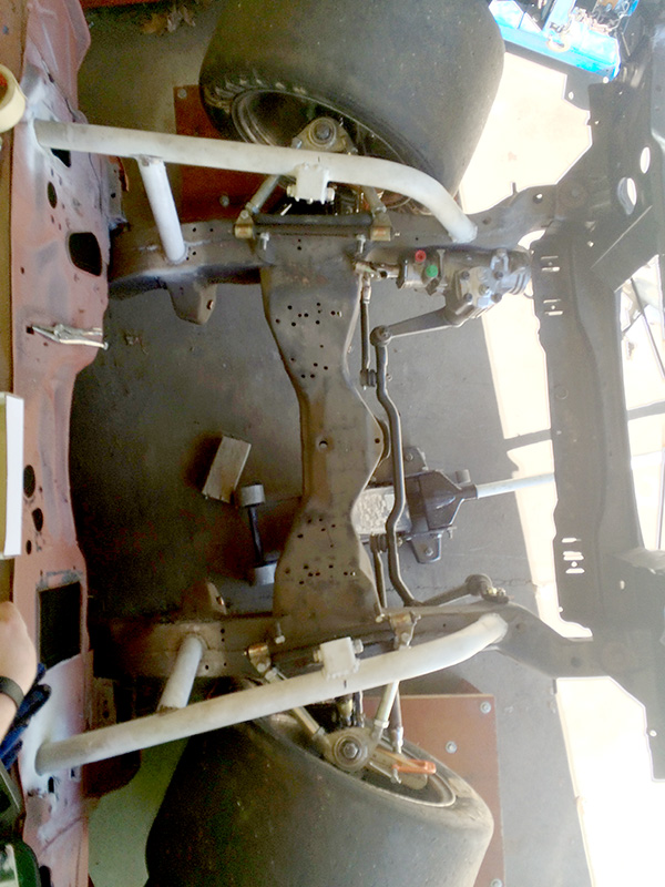
Granted, I couldn't quite get straight above, so there could be an optical illusion in the photo.
I then busted out the laptop, redid some of my measurements, and got a "better" picture of the car. The problem is I'm still not happy with what the software is showing me.
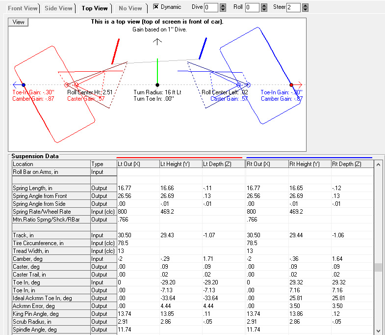
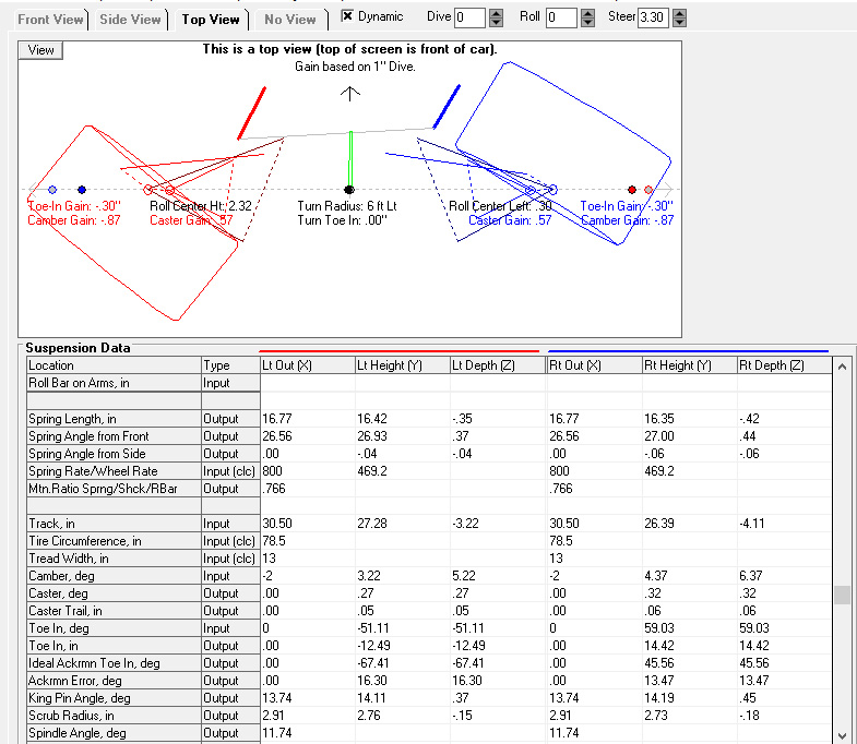
If I'm reading that right, the maths show that I actually have anti-ackerman. At this point, I'm not sure I can trust my measurements in the software.
What do you folks think? Does it look like, in reality, that I have ackerman and I should just go for it, or do I trust the software?
Not an expert by any means but here are my thoughts:
I think your center steering link may be too far forward relative to your spindles. the easy button for fixing the geometry would be to use a longer arm on the spindle but that would slow down your steering rate. Maybe combine a longer spindle arm with a longer pitman and idler arm set to gain some Ackerman and retain the desired steering ratio.
It looks like you have negative Ackerman. In the first simulation the inner spindle has 4.44 degrees too little steering angle and the outer has 3.50 degrees too much. Then at the extreme steering angle simulation the inner has 16.30 too little and the outer has 13.47 too much angle.
Also it looks like your pitman arm and idler arm are different lengths, that could cause some issues that would become more apparent as the steering angle is increased.
Are the numbers the same when you simulate a turn in either direction?
The_Jed wrote: Not an expert by any means but here are my thoughts:
That makes two of us...
The_Jed wrote: I think your center steering link may be too far forward relative to your spindles. the easy button for fixing the geometry would be to use a longer arm on the spindle but that would slow down your steering rate. Maybe combine a longer spindle arm with a longer pitman and idler arm set to gain some Ackerman and retain the desired steering ratio.
I really can't move the center link further back without running into the frame. A longer arm (or placement of the tie rod on the steering arm) is limited by the wheel size and having a reasonable amount of room to adjust for bumpsteer.
The_Jed wrote: Also it looks like your pitman arm and idler arm are different lengths, that could cause some issues that would become more apparent as the steering angle is increased.
That's the standard, stock stuff.
The_Jed wrote: Are the numbers the same when you simulate a turn in either direction?
Great question. I'm not sure. I'll take a look at it tonight.
It looks close to 0 Ackerman (parallel steering) from the pictures. Can you move the steering arm at the wheel towards the outside of the wheel further? If you can't you will need to move the inner steering arm mounts rearward. You could run spacers on the center link until the arms hit the crossbeam. I would think getting the steering arm pivots further into the wheel would help. I set the MG up (and the 2 FSAE cars before it) by using line of sight between the steering link balljoint and the kingpin axis. I made a line between those visually intersection a few inches in front of the rear axle pumpkin (~10% of wheelbase in front of rear axle on car centerline). The two FSAE cars drove well and the MG is close enough that it is easy to push around in the garage so it is at least near 100% Ackerman. Just looking at the pictures of your upright it looks like your steering arm would intersect somewhere well behind the rear axle. Looking at your model it looks like your steering arm is in fact parallel with the centerline of the car.
nocones wrote: Looking at your model it looks like your steering arm is in fact parallel with the centerline of the car.
I missed that!
Taking the spindle arms from [ ] to \ / (viewed from the top with ^ being the front of the car) could very well be what is needed.
nocones wrote: It looks close to 0 Ackerman (parallel steering) from the pictures. Can you move the steering arm at the wheel towards the outside of the wheel further? If you can't you will need to move the inner steering arm mounts rearward. You could run spacers on the center link until the arms hit the crossbeam. I would think getting the steering arm pivots further into the wheel would help. I set the MG up (and the 2 FSAE cars before it) by using line of sight between the steering link balljoint and the kingpin axis. I made a line between those visually intersection a few inches in front of the rear axle pumpkin (~10% of wheelbase in front of rear axle on car centerline). The two FSAE cars drove well and the MG is close enough that it is easy to push around in the garage so it is at least near 100% Ackerman. Just looking at the pictures of your upright it looks like your steering arm would intersect somewhere well behind the rear axle. Looking at your model it looks like your steering arm is in fact parallel with the centerline of the car.
I too worry that it looks close to 0 Ackerman as well. I can't really move the steering arms toward the outside of the wheel by much at all. At best, I think I could only get the centerline of the pivot point for the outer tie rod 1/2" outside of the centerline of the lower ball joint. To do any better, I'd have to have a new arm machined. To be clear, you are talking about moving the outer tie rod point further to the outside of the car - if that's true, I also have to consider brake clearance.
It might be a little hard to see here, but the old spindles I have angled the steering arm towards the center of the car.
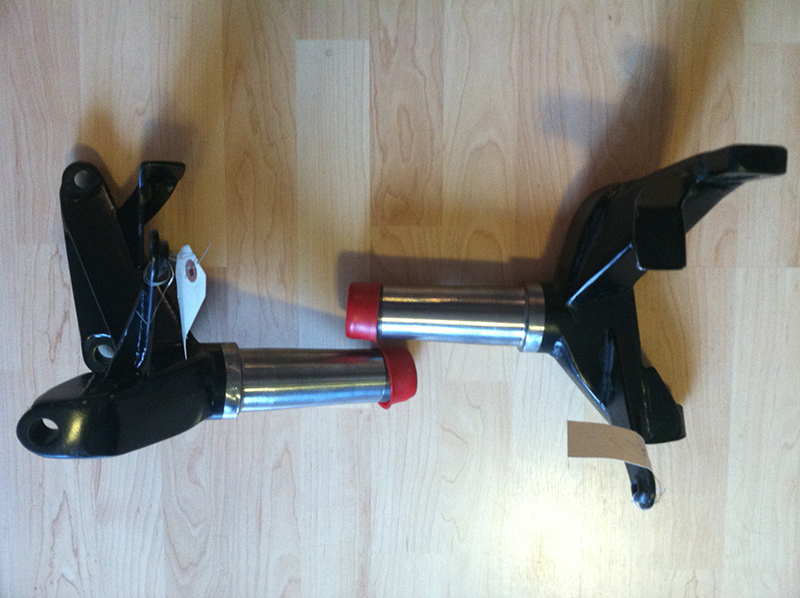
Spacers on the centerlink is an interesting idea that I could easily investigate if I don't get anywhere with the steering arms.
The_Jed wrote:nocones wrote: Looking at your model it looks like your steering arm is in fact parallel with the centerline of the car.I missed that! Taking the spindle arms from [ ] to \ / (viewed from the top with ^ being the front of the car) could very well be what is needed.
Yeah, the steering arms do complicate things.
I used photoshop to do a very, very elementary sketch of things. I put two guides, one for each axle, in the document 108 inches apart (the wheelbase of the car). I then added a guide for a centerline, and a guide 26" out from that centerline (since that was where my lower ball joint landed - going off of memory, i'll have to confirm). I then drew a line from the center point of the rear axle, through the intersection of the ball joint and the centerline. That gave me a line with an angle of 103.4 degrees. In order or achieve that angle, my tie rod, when placed 4 inches forward of the ball joint, needs to sit about 1 inch outboard of the ball joint. I don't think I have enough meat in my steering arms to pull that off, but it's a lot better than I expected.
Does that method make sense? Am I doing it right?
I have heard circle track will run anti-ackerman (meaning inside wheel turns less than outer). That would explain why the arms are that way on your spindle. I would think its worth making new ones if you have space before the disk.
nocones wrote: I have heard circle track will run anti-ackerman (meaning inside wheel turns less than outer). That would explain why the arms are that way on your spindle. I would think its worth making new ones if you have space before the disk.
I think you are right.
My photoshop method of drawing out the diagram, like this...
... gives me several points along the steering arm, depending on where I put the tie rod, fore or aft of the ball joint.
1" forward = 1/4" outboard
2" forward = 1/2" outboard
3" forward = 3/4" outboard
4" forward = 1" outboard
Which leads me to believe I should have plenty of room to get what I need before hitting the disk. If I bring my tie rods back a little (around 3" forward of the lower ball joint), so they are parallel to the lower control arms, I could likely use my existing steering arms, as they have enough "meat" to them to drill the offset.
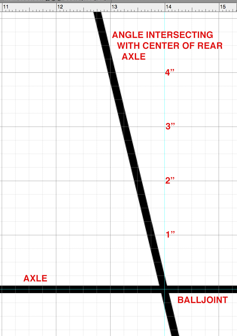
nocones wrote: I set the MG up (and the 2 FSAE cars before it) by using line of sight between the steering link balljoint and the kingpin axis. I made a line between those visually intersection a few inches in front of the rear axle pumpkin (~10% of wheelbase in front of rear axle on car centerline).
I updated the image with your 10% figure. Redrawn with the red line:
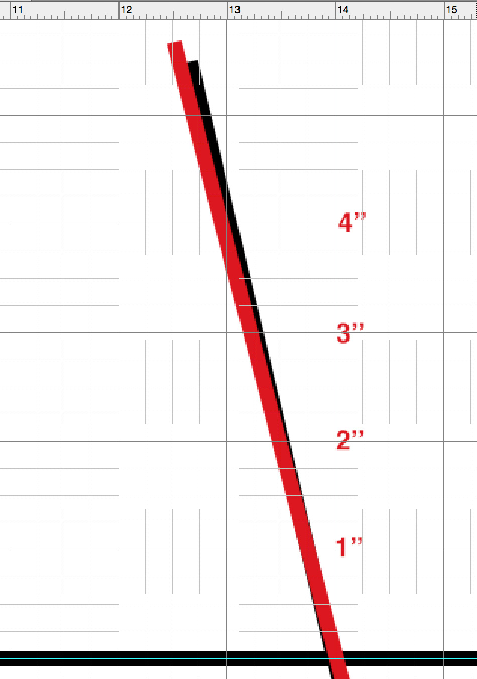
Still looks pretty doable.
Your on the right path. 1" seems reasonable, as does your arm length. Make sure you are accounting for KPI and Caster when doing math.
nocones wrote: Your on the right path. 1" seems reasonable, as does your arm length. Make sure you are accounting for KPI and Caster when doing math.
KPI is 10 degrees. Caster, not sure. I think I was looking at 4-6. How do these factor into the math?
The rotational axis for the spindle is between the upper and lower ball joints. It looks like your steering endlink ball is about 2" above the lower ball joint. That means you can't use the actual lower ball location as your pivot for Ackerman math you need to adjust the apparent location in your calculations. 10* KPI and 2" vertical relative to LBJ would move the pivot towards the car centerline ~3/8" at the steering ball elevation. Caster would move it back however this will have less of an impact on the result because the geometry is less effected by fore aft locations then width.
So you need to determine the height of the steering ball. You can then do the math based on that position. The actual geometry would consider the arm as being perpendicular to the King Pin axis and you can model it this way however I think just redoing your math as a horizontal plane at the elevation of the steering ball will make the math good enough.
I can do some illustrations tonight at home it it's still unclear. Steering arm geometry is tricky but worth putting the understanding into because it can be frustrating to fight with once the car is running if its wrong. I've always leaned towards a bit more inner tire turn than 100% Ackerman just because it makes the car easy to push around (meaning less than wheelbase intersection length). We played with Ackerman intersections between 50% wheelbase and 120% wheelbase on one of the FSAE cars and ~90% wb gave us the best compromise of good turn in and good skidpad performance and still allowed easy paddock car movement. I've still not seen a good definitive guide on what XX% Ackerman means. 0% is parallel steer and 100% is geometric perfect meaning a line extending from all 4 tires hub would intersect in the geometric center of a turn (no bind when pushing car). What I've not seen explained is what 80,90,120% Ackerman mean. Is that the amount the inner tire turns relative to 100%? I just don't know so I talk about the intersection of the steering arms as its easier to visualize and communicate.
My steering end link, which I'm calling the outer tie rod, will actually be about 2 inches below the outer lower ball joint. It looks a little strange in the photo, but that's because of how I had to attach the arm.
Thank you so much for all the info here. I'm a bit in the dark on this stuff, so it's great to have help from folks who know more!
So, I took a moment and mapped that angle from photoshop onto the steering arms:
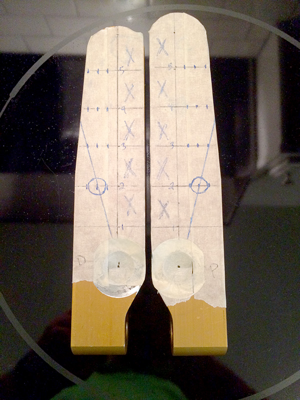
Unfortunately, that showed me I don't have a lot of room on the steering arms as they were delivered, without worrying about strength. Based on that info, I played around in the software more.
MORE BORING SCREEN SHOTS
Here is the screen shot with the tie rods attached to the circled spot on the steering arms:
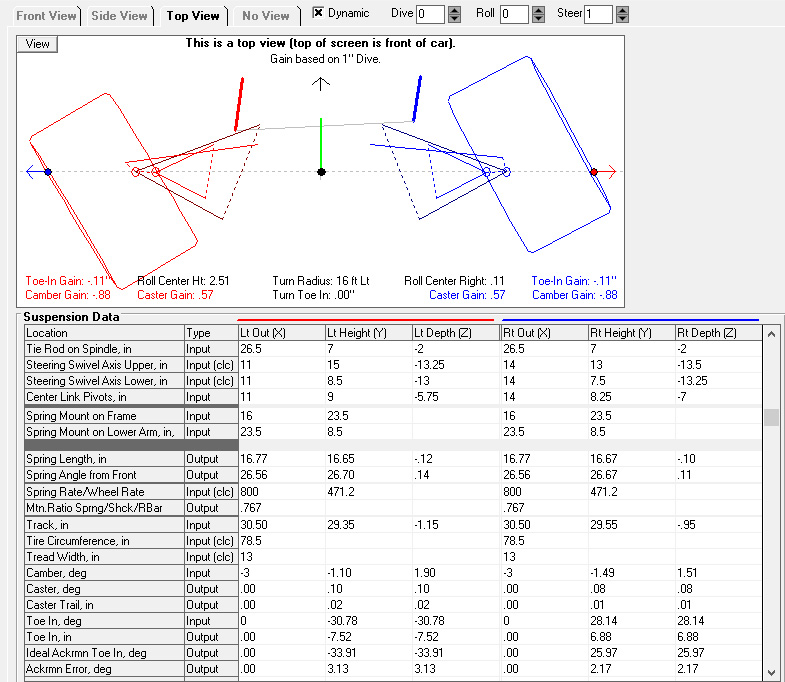 Ackerman error is at 3.13 left and 2.17 right - not the best.
So then I moved the tie rod attachment point forward an inch. I did not change the distance side to side, only the distance from the lower ball joint:
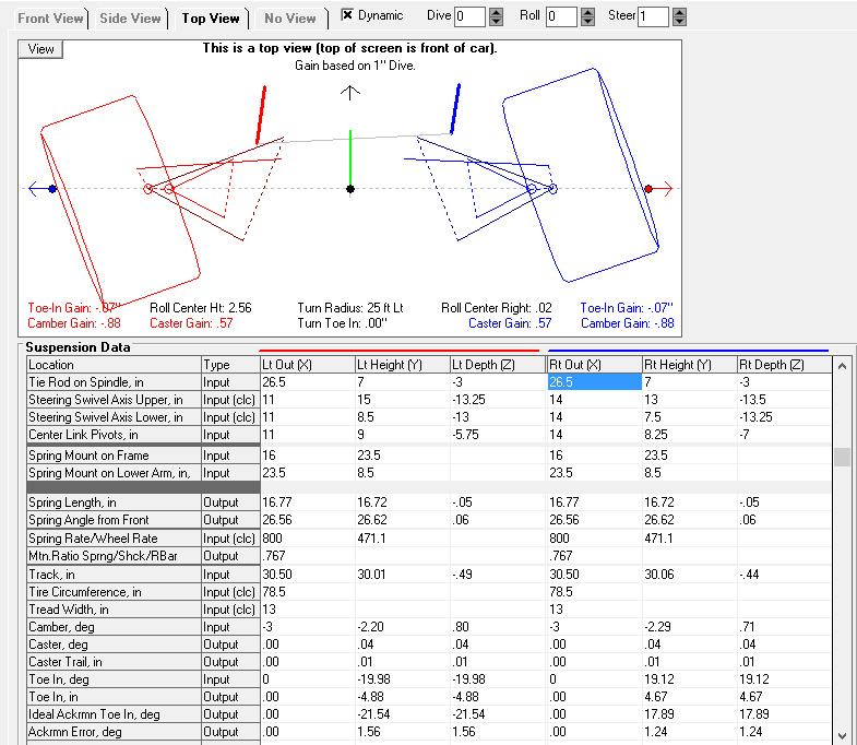 Ackerman error goes to 1.56 left and 1.24 - seems to be getting better?
Excited by that "progress," I moved the tie rod attachment points one half inch further - about the farthest I could go given my current steering arms. Just like before, the distance outboard was not changed:
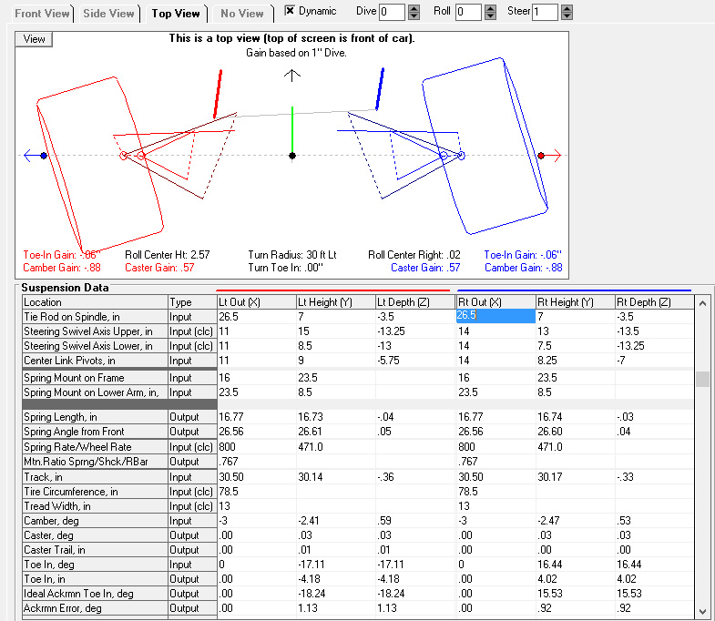 Ackerman error is now 1.13 left and .92 right - even better!
YOU ARE BORING US, WHAT DOES IT ALL MEAN?
It means I still don't trust my software. For whatever reason, things in real life seem to tell me the opposite of what the software says. I've measured things a whole bunch, but I just don't trust it.
Thoughts?
loosecannon wrote: Are your front and rear lower control arm measurements really that different?
Yes, but I'm still an idiot. I do have those wrong. I have the forward attachment point way too forward. The forward part of my lower control arm should be perpendicular to the centerline of the car. So my distance apart is likely correct, but I have the front attachment point way too forward in the software. Looking at this picture:

You can clearly see the rear attachment point on the left. You can also see the bolt head for the forward attachment point on the front side of the cross member, almost in line with where the pitman arm is pointing.
Another shot from earlier in the thread:
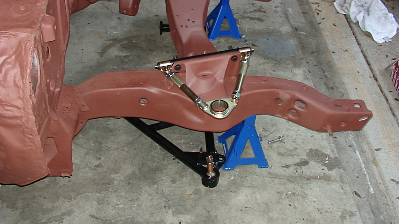
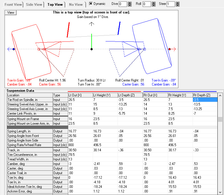
After fixing that, the change in ackerman error was negligible.
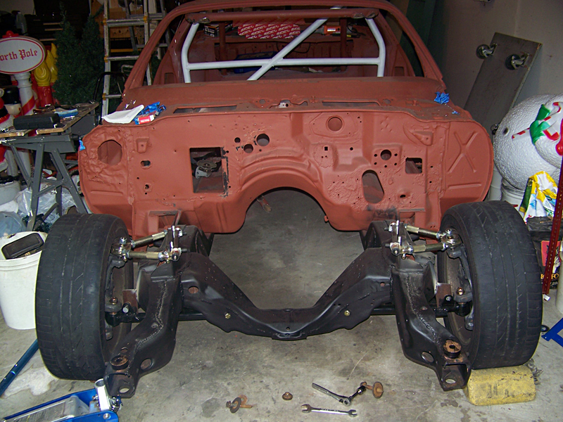
You can also see, in this picture, where the stock steering arms where:
You'll need to log in to post.