Continuing my efforts to manage under hood airflow and pressure I wanted to seal off the inner fender wells above the frame. The stock inner fenders have a factory installed "splash shield" which helps separate the air in the inner fender from the engine compartment. I wanted to take that a step farther. So I made up some patterns and used 1/8" EPDM rubber sheet to more effective seals. I'm going to be running the modified stock upper control arms for a while after reassembly but plan on eventually switching to upper and lower arms that will allow more positive castor and negative camber so I'll need to reconfigure the seals. With that inn mind I'll be using threaded hardware to hold the seals during assembly after paint now but may use pop rivets to save a little weight when the tubular arms are installed.
Stock splash guard in pic below. Note the gaps to the inner fender well not only around the control arm but also where there was no stock shield between frame and inner fender.
[URL=http://s240.photobucket.com/user/NOTATA/media/The%2014%20Car%20Performance%20Therapy/010_zpsvv9h3ux2.jpg.html]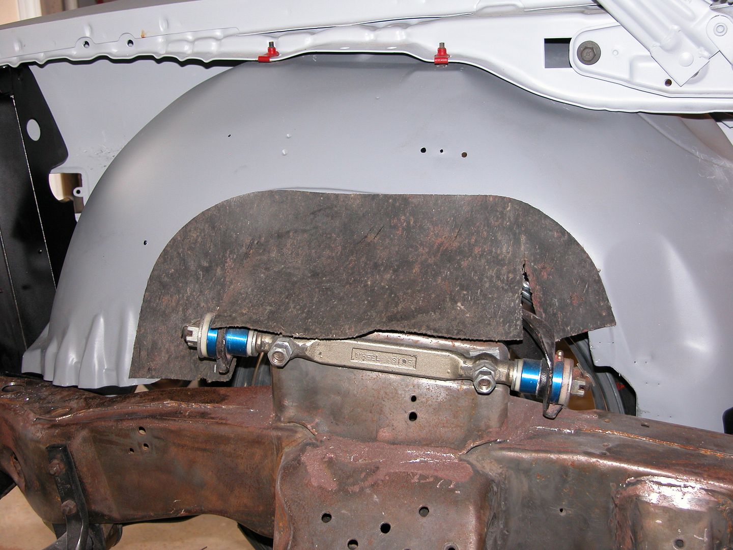 [/URL]
Pics below show pattern making and the new seals in place.
[URL=http://s240.photobucket.com/user/NOTATA/media/The%2014%20Car%20Performance%20Therapy/012_zpshwsa9axw.jpg.html]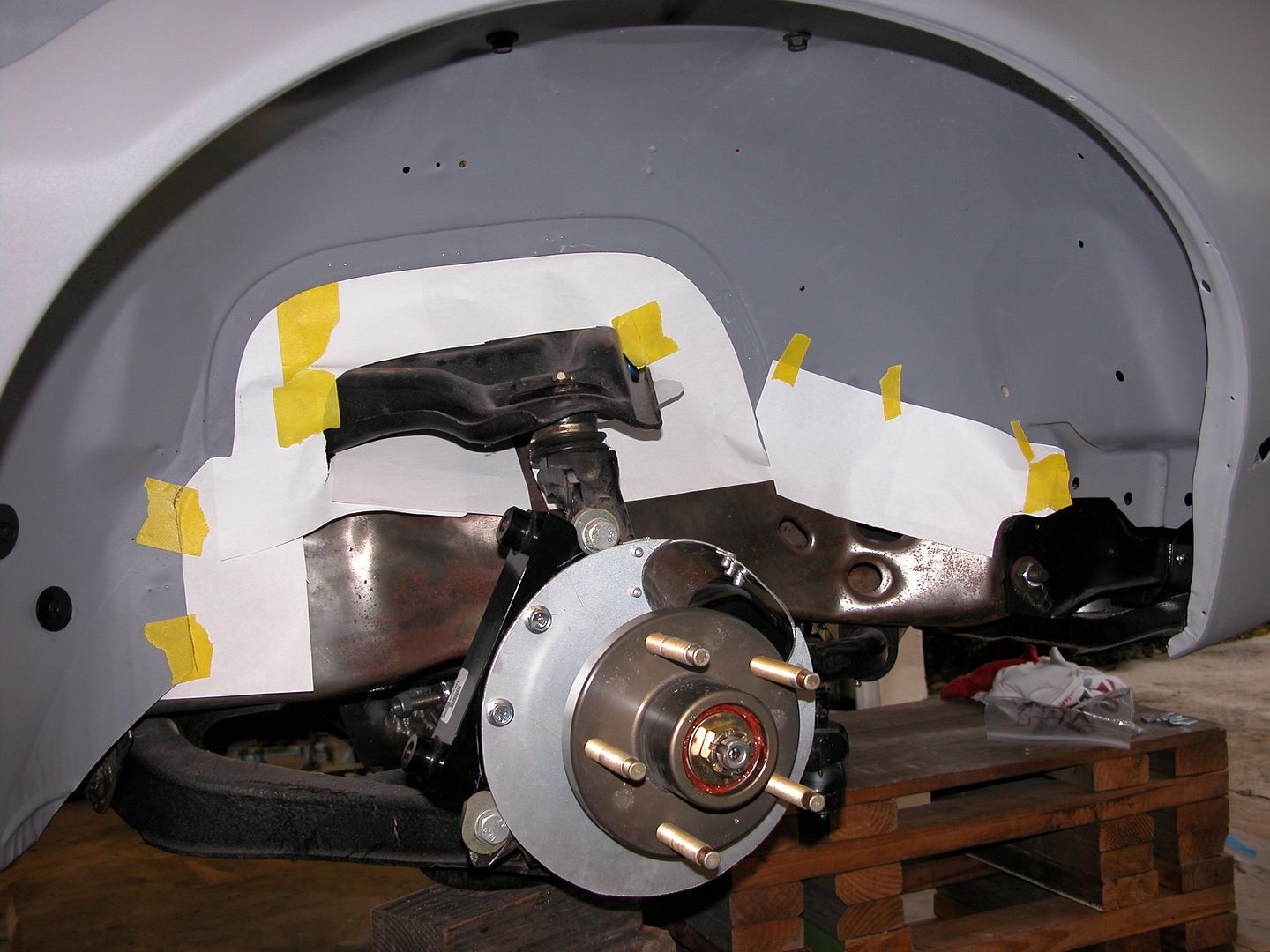 [/URL]
[URL=http://s240.photobucket.com/user/NOTATA/media/The%2014%20Car%20Performance%20Therapy/016_zpszu3fo1iv.jpg.html]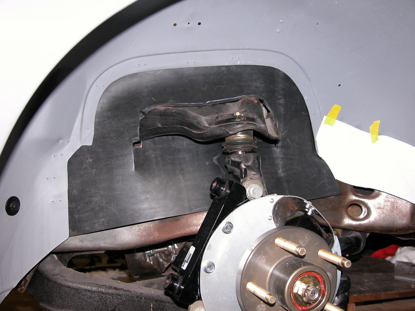 [/URL]
[URL=http://s240.photobucket.com/user/NOTATA/media/The%2014%20Car%20Performance%20Therapy/002_zpsdxmtqtsj.jpg.html]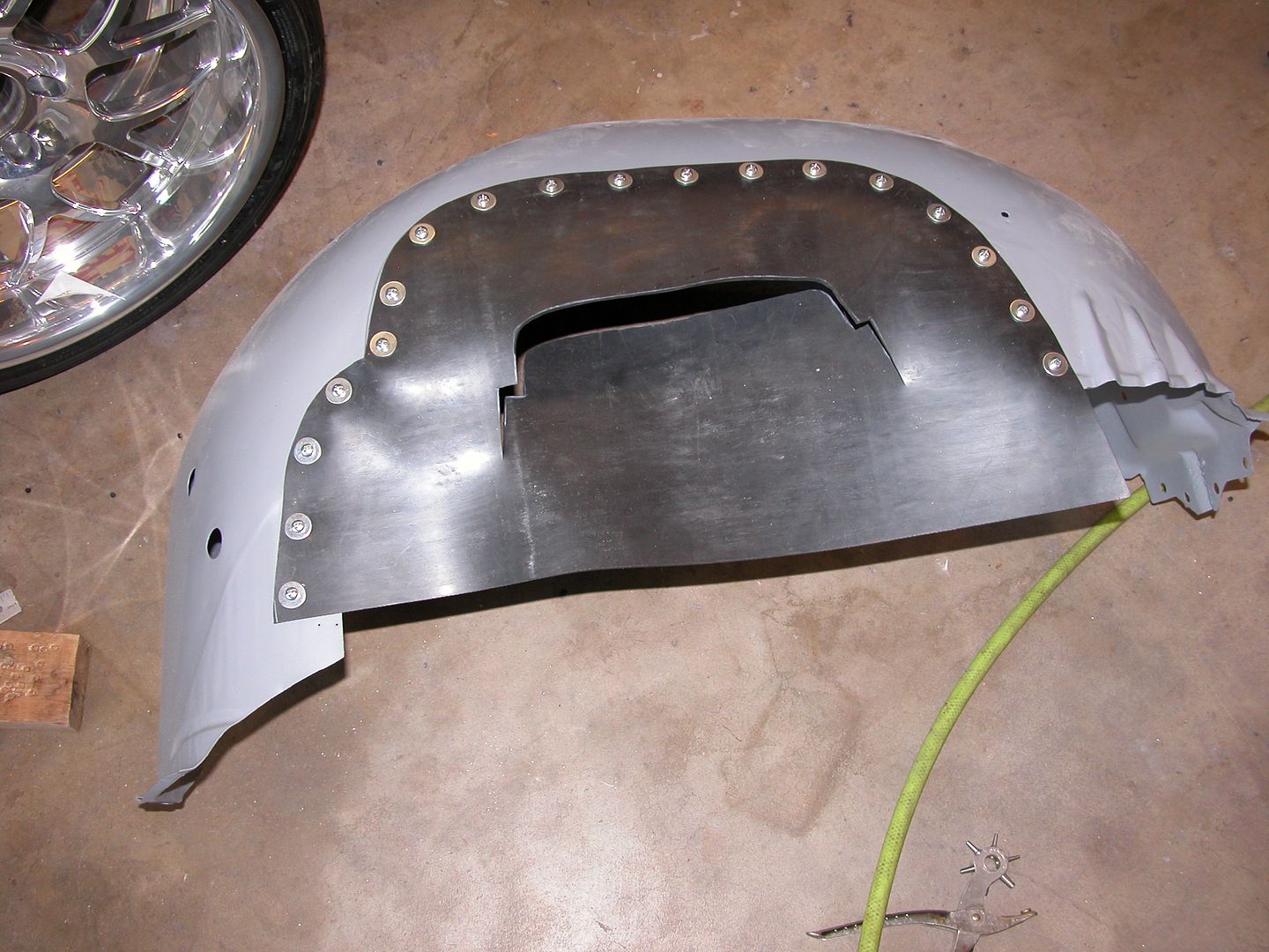 [/URL]
[URL=http://s240.photobucket.com/user/NOTATA/media/The%2014%20Car%20Performance%20Therapy/006_zpsgyzwmeqk.jpg.html]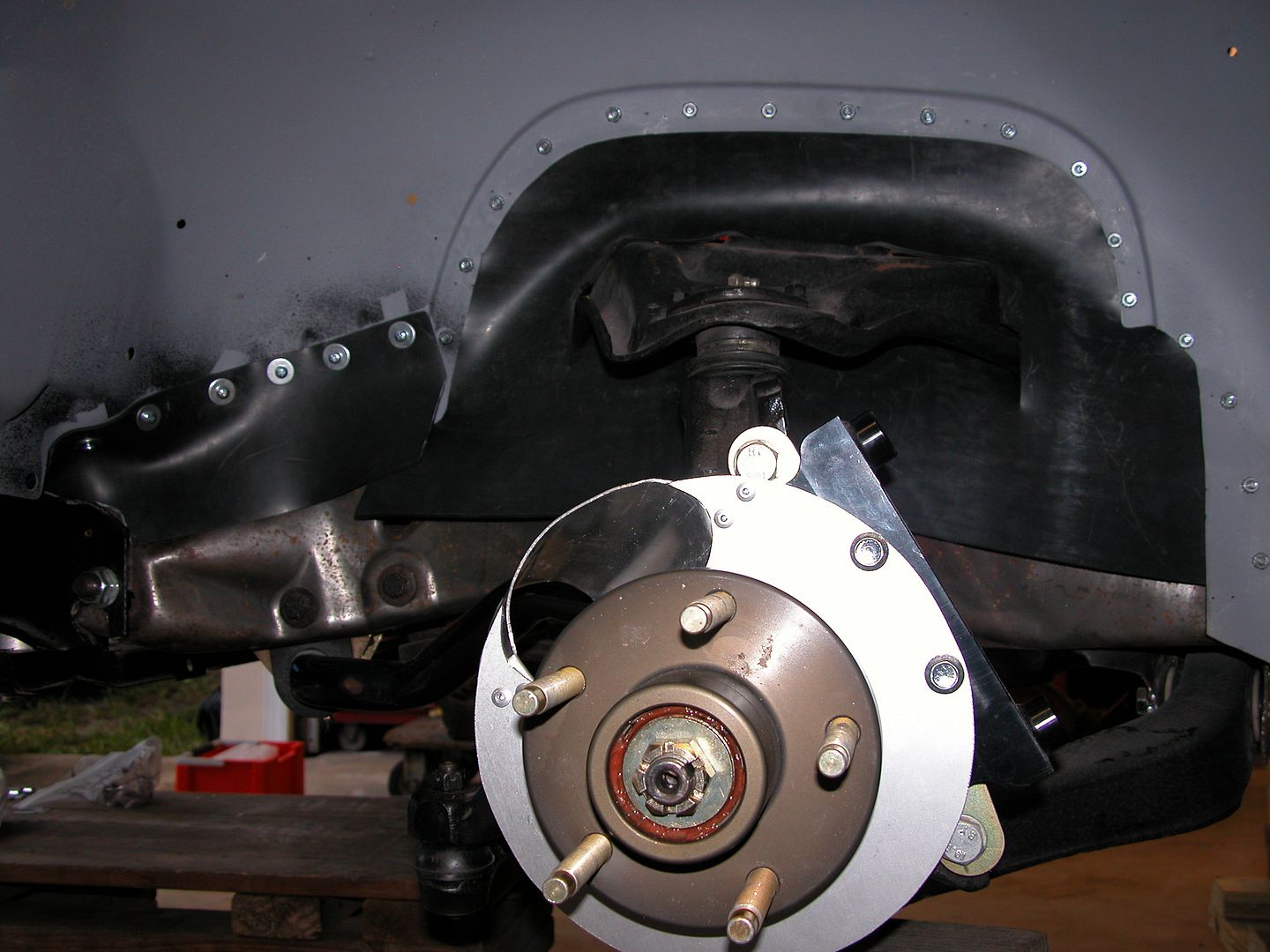 [/URL]
How did you lay out your fastener spacing? I'll actually be installing some splash shields this week with pop rivets and am trying to figure out how to lay out the pattern.
Dusterbd13 wrote: How did you lay out your fastener spacing? I'll actually be installing some splash shields this week with pop rivets and am trying to figure out how to lay out the pattern.
The 3/32" EPDM rubber I used to seal off sections of the core support seemed to work well with 2" Rivet spacing using 3/16" rivets with 3/16" body washers. I repeated the spacing using 1/8" rubber for the wheel well seals so the patterns would look the same in the engine compartment. Make the shape of the rubber piece from the paper pattern, then make the holes for the rivets in the rubber (belt hole punches), then use the rubber piece as a template to mark where to drill the holes in the sheet metal.
Will post about core support seal project after I finish it up tomorrow.
[URL=http://s240.photobucket.com/user/NOTATA/media/The%2014%20Car%20Performance%20Therapy/025_zpssmilr3ck.jpg.html]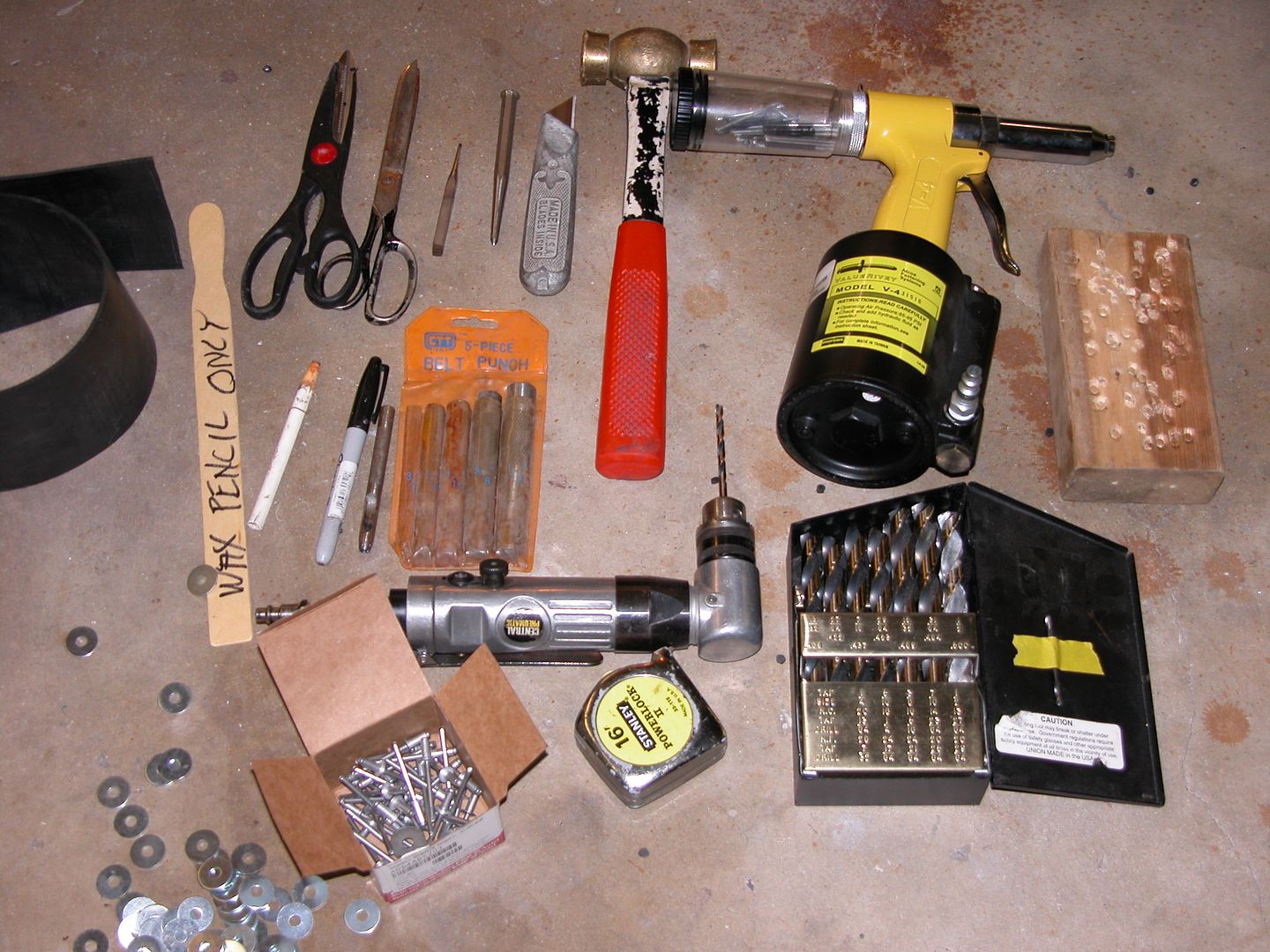 [/URL]
[URL=http://s240.photobucket.com/user/NOTATA/media/The%2014%20Car%20Performance%20Therapy/009_zpskigprc0s.jpg.html]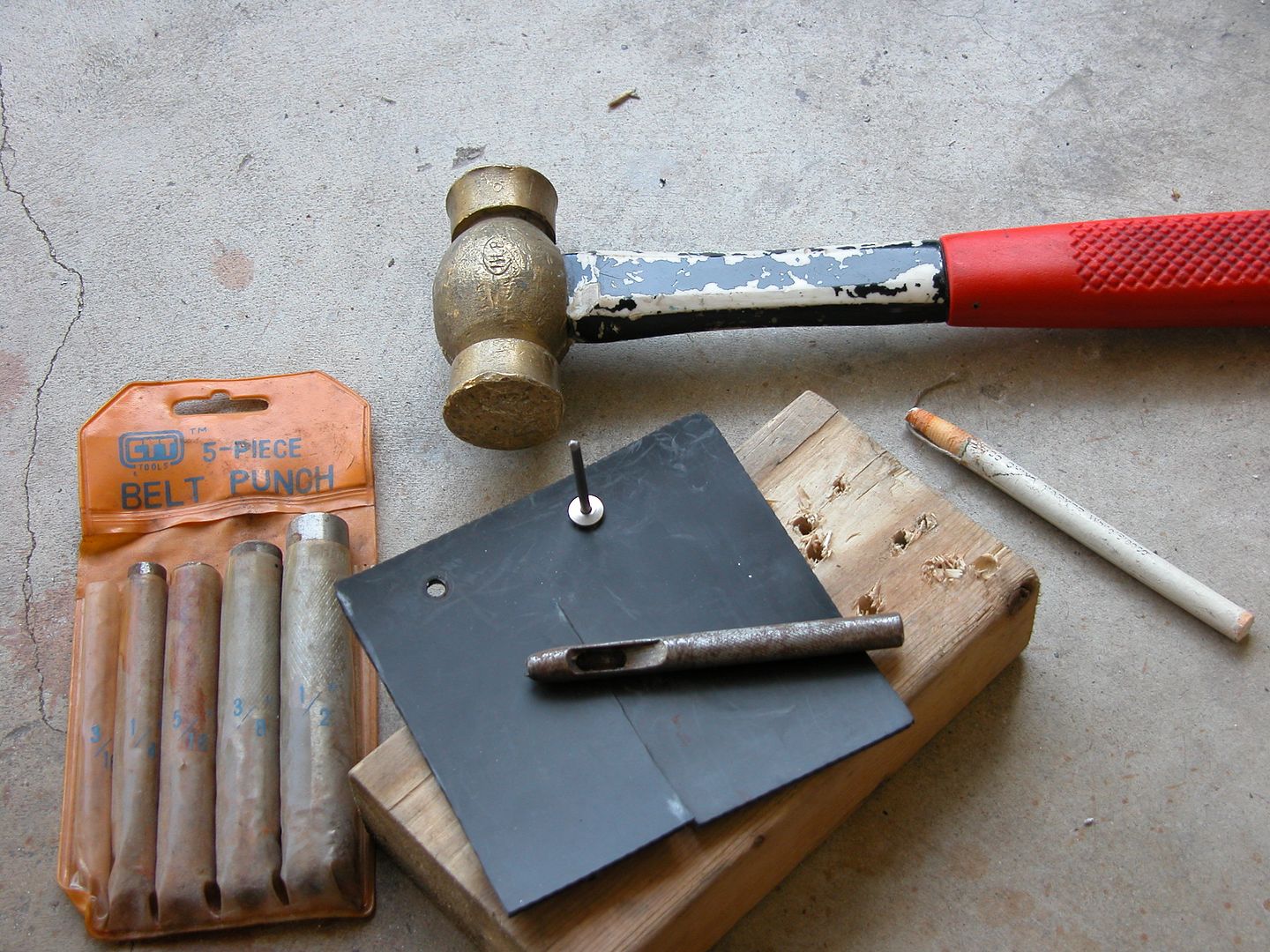 [/URL]
[URL=http://s240.photobucket.com/user/NOTATA/media/The%2014%20Car%20Performance%20Therapy/001_zpshnu7yfwp.jpg.html]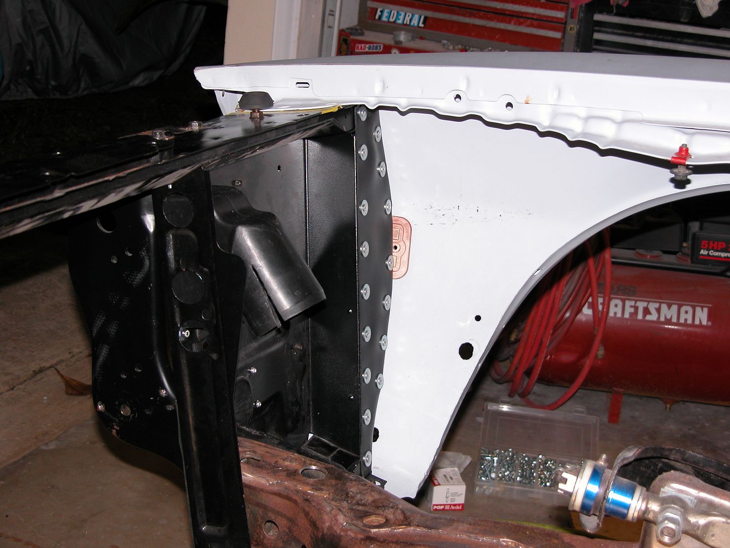 [/URL]
The inner fender extensions on the 70-73 birds rusted out pretty easily and over the years I've seen a lot of cars missing them completely. It's a part some might just consider part of the crash protection crumple zone or be considered more of a splash guard. However it's also a part that affects aero. Without it the air coming under the front air dam collides with the air in the wheel well and seeks a place to go. I believe that the air will flow through the opening into the area behind the core support.
Twenty five years ago when I first built the car reproductions weren't available and I didn't really have a way to make replacements. I cut off the bottom of one of them because the rust had eaten it all up while the other had rust holes but wasn't as bad. Eventually I got a better (but not great) set off a parts car and planned on installing them.... Ya, never got around to that, and they disappeared along the way. Reproductions are available now, but I have the ability to make them so I did. If it was a customer car I'd have installed repros because of the fabrication labor time, but since it's my car I made them.
[URL=http://s240.photobucket.com/user/NOTATA/media/The%2014%20Car%20Performance%20Therapy/004_zps1slxm8yg.jpg.html]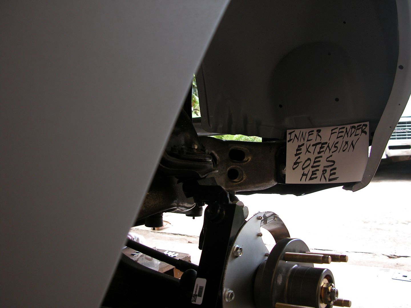 [/URL]
[URL=http://s240.photobucket.com/user/NOTATA/media/The%2014%20Car%20Performance%20Therapy/007_zpsct2kaqvr.jpg.html]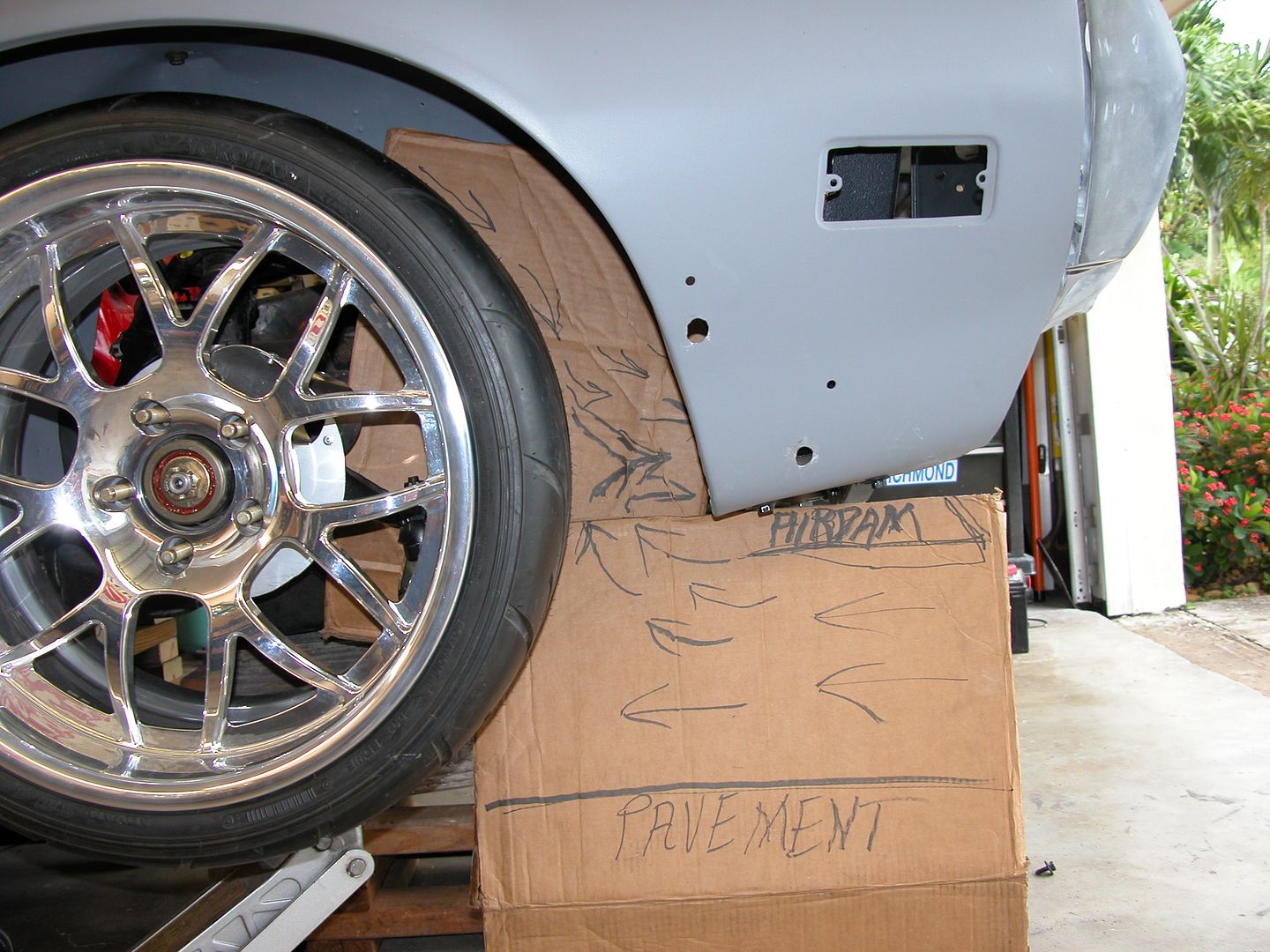 [/URL]
[URL=http://s240.photobucket.com/user/NOTATA/media/The%2014%20Car%20Performance%20Therapy/002_zpszbemqha6.jpg.html]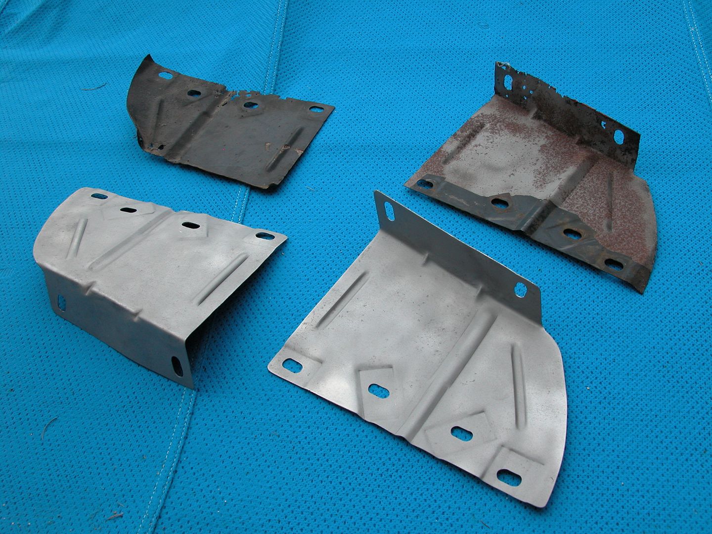 [/URL]
The core support of the early 2nd gens had a lot of gaps on the sides and top as well as large openings for the bumper supports to pass through it. I wanted to seal these areas off to keep the air out which should reduce under hood air pressure and increase the difference in pressure in front/back of the radiator which will help the radiator be most efficient.
Now those of you with early 2nd's might go look at the car and think pffft there's only an inch gap here and there and the holes for the bumper supports. However even though they're not directly open to the front of the car the cavity between the core support and the bumper/splash pan is one of (if not the) highest air pressure areas on the car. So the air is trying to get past the core support through the gaps as fast as it can. This is the same principal of why the brake cooling duct openings are placed in the core support rather than on the splash pan.
So how big are the gaps really? I added them all up, then recalculated thinking I must be wrong but no.... Imagine a hole this big in the core support letting air in!
[URL=http://s240.photobucket.com/user/NOTATA/media/The%2014%20Car%20Performance%20Therapy/004_zps0p3djf7f.jpg.html]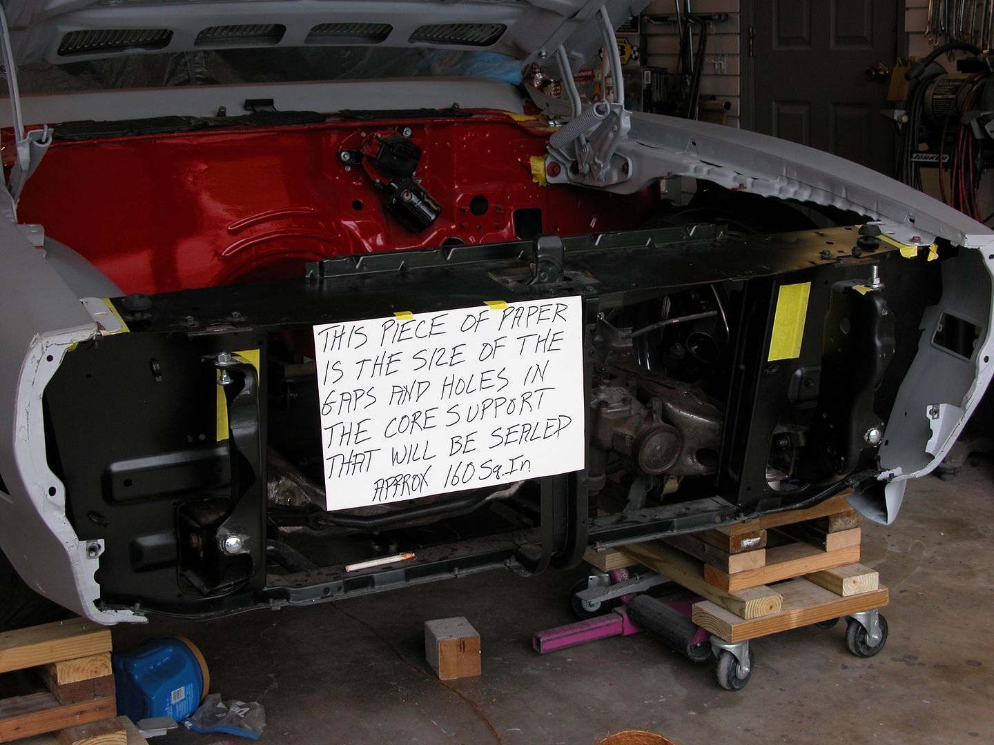 [/URL]
The bottom of the core support is bolted tight to the lower edge of the splash pan sealing it. So the sides, top, and bumper openings are where I needed seals. To seal the sides and bumper holes I used 3/32 EPDM rubber sheet and pop riveted it in place. 3/16" aluminum rivets with 3/16" body washers.
[URL=http://s240.photobucket.com/user/NOTATA/media/The%2014%20Car%20Performance%20Therapy/008_zpsogxtjqrc.jpg.html]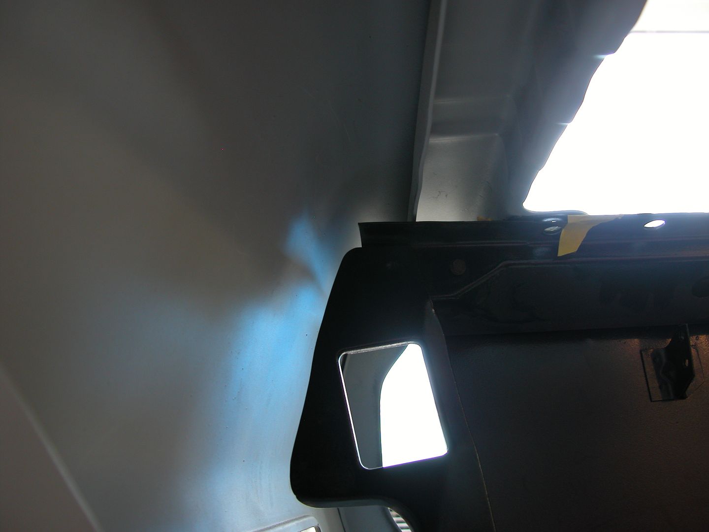 [/URL]
[URL=http://s240.photobucket.com/user/NOTATA/media/The%2014%20Car%20Performance%20Therapy/010_zpslkdr0i3b.jpg.html]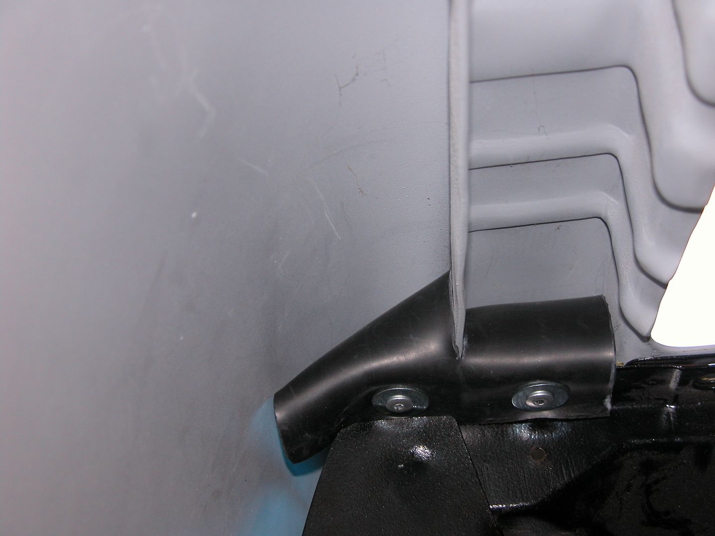 [/URL]
[URL=http://s240.photobucket.com/user/NOTATA/media/The%2014%20Car%20Performance%20Therapy/016_zpsfeey0euo.jpg.html]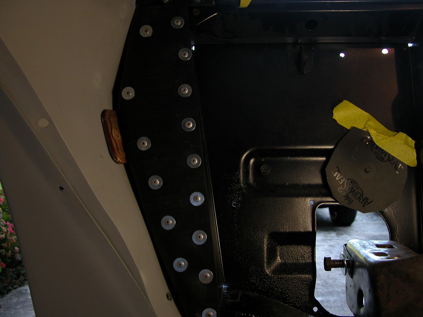 [/URL]
[URL=http://s240.photobucket.com/user/NOTATA/media/The%2014%20Car%20Performance%20Therapy/007_zps1zv3uuom.jpg.html]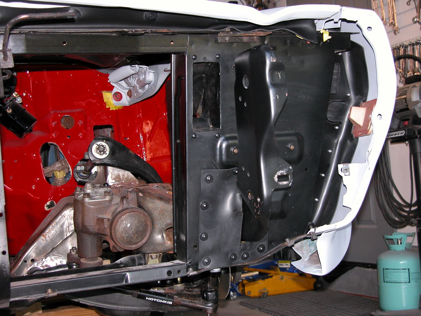 [/URL]
To seal the top of the core support I used the same rubber but with plastic push pin fasteners for a more finished factory look. All of the seals will become tighter as air pressure increases forward of the core support with speed.
[URL=http://s240.photobucket.com/user/NOTATA/media/The%2014%20Car%20Performance%20Therapy/002_zpspdcspzhy.jpg.html]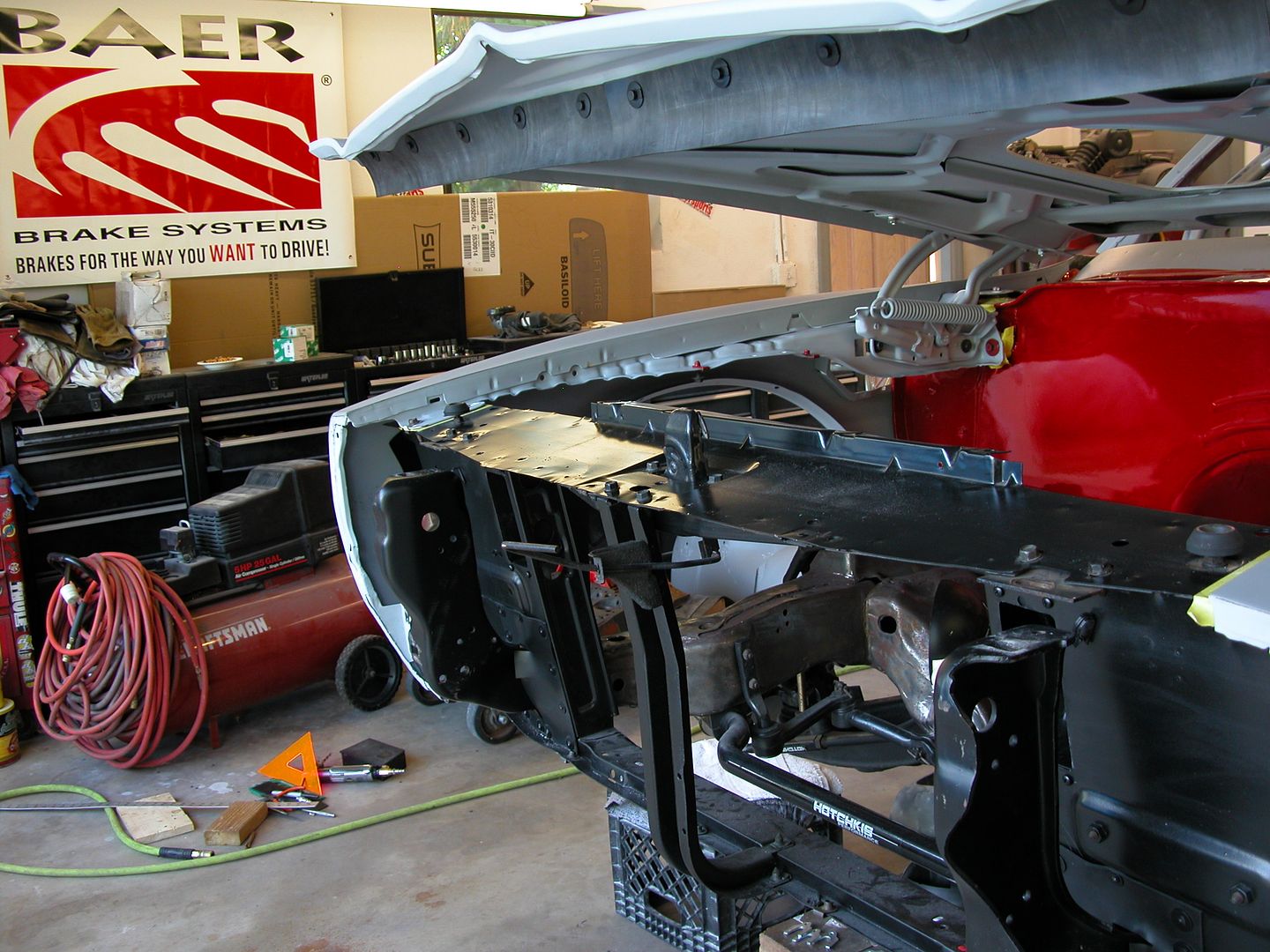 [/URL]
[URL=http://s240.photobucket.com/user/NOTATA/media/The%2014%20Car%20Performance%20Therapy/001_zps268td2lo.jpg.html]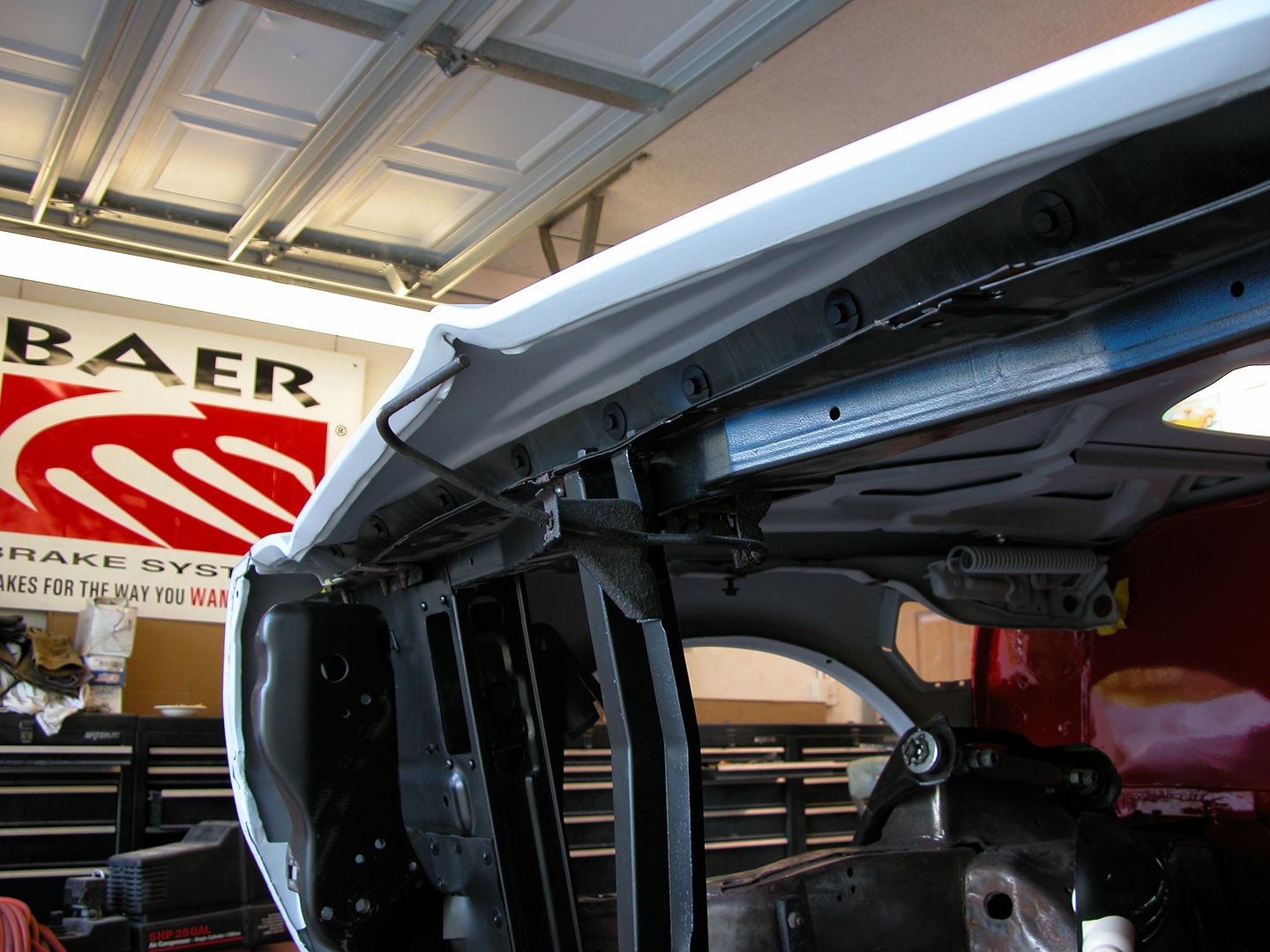 [/URL]
As always, very educational, and thanks for that.
Where did you source the 1/8 inch EPDM rubber? Did it come in a roll? I'm off to Google...
Edit. Okay, I can get it at Amazon, Grainger, etc. Great tip none the less
Reminds me of the engine bay of my f150 ecoboost. You can tell ford went to great lengths to try control airflow and increase gas mileage. Lots of things that look very similar to your fabricated pieces in the engine bay.
wheelsmithy wrote: As always, very educational, and thanks for that. Where did you source the 1/8 inch EPDM rubber? Did it come in a roll? I'm off to Google... Edit. Okay, I can get it at Amazon, Grainger, etc. Great tip none the less
All the rubber pieces came from McMaster Carr. If you use it for a similar purpose keep in mind as you cut the pieces that the rubber sheets aren't perfectly flat because of the manufacturing process and want to roll (very slightly) in two directions as if to be bowl like. Turn the sheets so they want to press against the sheet metal you want the rubber to seal to before cutting or you'll have an "inside out" condition where the edge of the rubber curves slightly away from the metal you want it to seal against.
Mad_Ratel: Ya, you'll see the modern cars have a lot of aero things that trickled down from race cars of years gone by. There's been huge advancements in race car aerodynamics in the past 45 years since my car was built. I'm trying to update the aero on this car to what the Pontiac engineer race guys might have done back when they made these cars (to race) if they had today's aero knowledge. Frontal area, windshield rake and other things can't be changed but other things are fair game as far as I'm concerned. I don't have to build to any rule set, so I'm "playing".
Are you going to install a flatbottom? If so, a high pressure area under the hood might be a nice reservoir of air from which you could cool your brakes. I did something similar on my Daewoo of Death (although much more crudely) and reaped many benefits including about 15% better fuel economy on the highway, a little bit of downforce in the front, cooler brakes and about 10% better top speed. With all the effort you're putting into sealing, you will probably do better than I did.
Flat bottom to rear diffuser is the current plan although I'm considering the possibility of tunnels.
Brake ducts are fed from high pressure in front of core the support under the hood. I'm trying to reduce pressure under hood in the engine compartment area to reduce lift/increase down force.
[URL=http://s240.photobucket.com/user/NOTATA/media/The%2014%20Car%20Performance%20Therapy/004_zpsaxq1s3fe.jpg.html]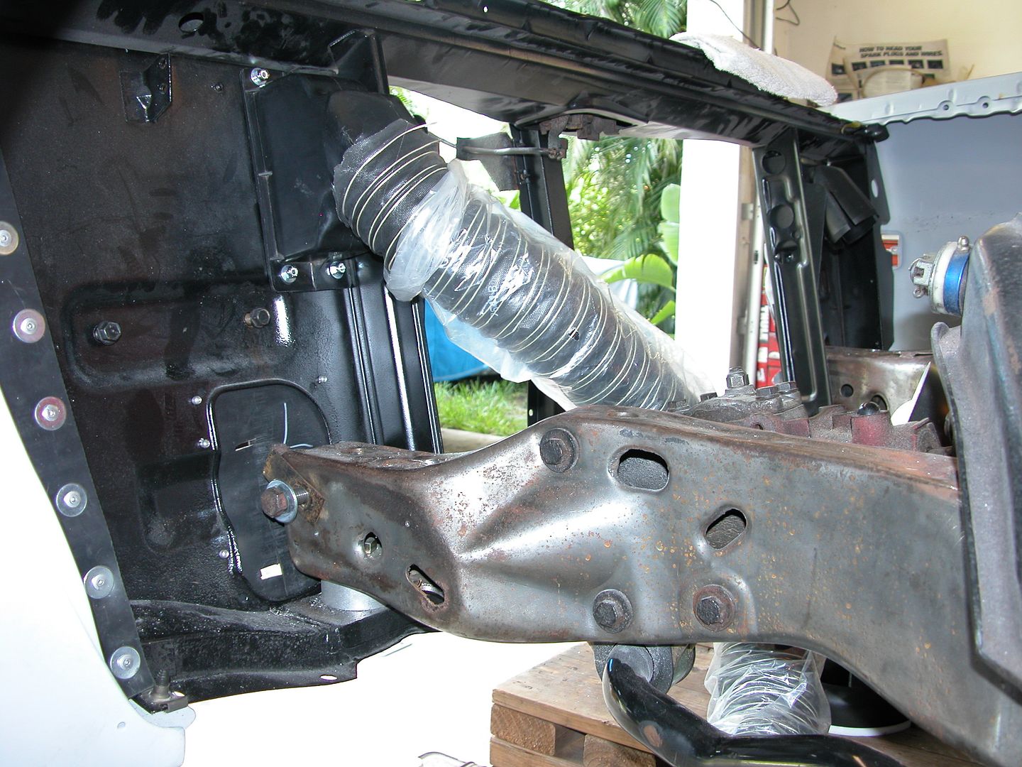 [/URL]
asifnyc wrote: Great stuff john and very relevant to my current pursuits. Any updates?
I was glad to see your Jav project pop back up although sad to see what was necessary to fix the accident damage.
I've been doing something on the car every day. A lot of the time the past couple months was spent on bodywork for the doors and front end aligning and smoothing. Once the body panels were all ready for final primer I took the whole car back apart so I could work on drive line, exhaust, under tray mounts, etc. I've also been working on a lot of small things that are part of bigger projects. As each of the smaller projects is completed I'll post about them. At the present I'm mocking up the driveline and new (NOS) side pipes. The '81 frame I'm using didn't have mounting holes for the '70 engine and trans mounts (plus I want to move them back a bit if possible). Side pipes are different than my old ones and didn't come with mounting hardware so I've gotta fabricate new mounts for those also. Trying to do all these types of things before paint.
Pics from yesterday
[URL=http://s240.photobucket.com/user/NOTATA/media/The%2014%20Car%20Performance%20Therapy/003_zpsjbdbay8k.jpg.html] [/URL]
[URL=http://s240.photobucket.com/user/NOTATA/media/The%2014%20Car%20Performance%20Therapy/004_zpswpi4lpy3.jpg.html] [/URL]
G braces have been around since Herb Adams & his crew were racing 2nd gens back in the early 70's. The basic brace idea itself was/is a good concept which triangulates the front sub frame to the upper cowl. This reduces deflection of the stock sub frame and stiffens up the overall platform so suspension and steering components can do their job better.
The Pro-Touring F-Body Gen II adjustable G-braces shown here evolved from the simple early braces and are a great product. They're a very stout design with a nice adjustable feature that allows them to be easily installed on most 2nd gen F body's. The braces are actually much stronger than the cars they're being installed in and that is the focus of this post. By modifying the points where the forces transferred by the G-braces act on the cowl, upper control arm mounting bolt, upper control arm mount, and sub frame we can make the G braces function even better whan the car is pushed to it's limits.
In my opinion G-braces should only be used on cars with solid body mounts as a minimum, and preferably have sub frame connectors also. Doing any of the modifications discussed in this post without solid body mounts is a waste of time and money (even if you think it looks cool). Additionally, if you're not really pushing the limits of the car at auto-X, hill climbs, or on road race tracks it's doubtful the benefits of most of this additional bracing would be noticed. However I do believe the upper control arm bolt support would be a good addition to any car with any type of G-brace that uses the upper control arm cross shaft mounting bolt as the G-brace lower mounting point.
So here's my list of areas that can use a bit of improvement and what I've done. I hope this helps for those who might want to copy what I've done or come up with better ideas. As with most things the evolution will continue.
Also for those wondering, Dave at PTFB has been kept in the loop while I was designing/prototyping all these things. You can expect a new bolt on center upper G-brace to cowl support to be available from PTFB very soon. Top secret at the moment so I can't disclose details but Dave should be announcing soon. Where the ones shown below only fit low valve cover Pontiac set ups the PTFB one's will fit multiple applications for those with tall covers, LS engines etc.
Improvement 1. A strip of 1/8" steel plate above and below ledge creating a sandwich and bolted through the pinch welded area. Stiffens the ledge and spreads the force from the brace over a much wider area. Creates a wider thickness for shear forces transferred through the bolts to act on by doubling (or rmore) the thickness of the ledge. Provides a strong section in the center of the cowl ledge where the top of the cowl is stiffer for the additional centered mount triangulation braces I made that do not come with G-braces. The additional braces also provide lateral support. I used bolts but the sandwich plates could be welded in place.
Improvement 2. Weld a piece of 1/8" flat plate to the face of the UCA mount. Most of us with track cars are already running a bunch of shims on the front and rear UCA shaft bolts to get as much positive castor and negative camber as we can. The 1/8" plate eliminates one shim front/rear and eliminates one surface where things could slip/move.. The 1/8" welded plate increases the thickness of the mount to 5/16 which is a 66% increase and stiffens the mount. Additionally it gives a thicker more solid base for larger splined UCA shaft mounting studs/bolts.
Improvement 3. ARP 1/2" wheel studs with a wide spline base to replace stock UCA shaft bolts. The wide base makes the bolt more stable and spreads force over a bigger area. The spline area is also deeper which combined with the additional thickness provided by the 1/8" plate welded to the mount keeps the bolt more stable. The wheel studs are also longer allowing shims etc. to run a lot of negative camber while still easily double nutting the bolts with grade 8 nuts to prevent loosening. The ARP long studs are stronger and also allow space to utilize an additional support for the stud to transfer force to the frame horns ahead of the UCA mounts.
Additional improvement. Adjustable UCA bolt brace between the front UCA bolt/stud and the frame on roughly the same angle as the main tube of the G-brace.. This support transfers loads from the G-brace to the front frame horns reducing the load on the spline section of the UCA bolt by providing additional support on the other side of the G-brace to help prevent tipping or wiggling of the UCA bolt/stud. I feel this is the most beneficial modification and recommend it to anyone using any style of G braces that use the UCA mounting bolt as the lower attachment point.
Pic below is an overview showing everything mocked up but not yet fully adjusted and tightened. The sub frame will need to come out for paint after other modifications are done. The bolts and nuts are all serrated flange locking fasteners excluding the ARP studs & grade 8 nuts used for the UCA shaft mount. On the cowl, the top of the G-braces are fastened with 7/16" bolts and the other bolts (including the additional upper braces) are all 3/8". The lower supports for the UCA bolts are fastened to the frame with 1/2" serrated flange nuts/bolts.
[URL=http://s240.photobucket.com/user/NOTATA/media/The%2014%20Car%20Performance%20Therapy/005_zpsyyvci1im.jpg.html]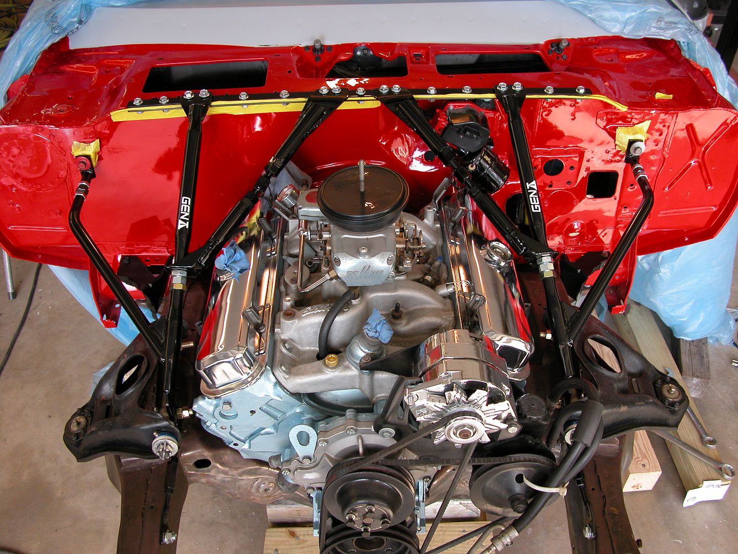 [/URL]
Pic below shows the 1/8" thick plate welded to the UCA shaft mounting surface. Note the thickness where the splines of the stud will hold the bolt more securely.
[URL=http://s240.photobucket.com/user/NOTATA/media/The%2014%20Car%20Performance%20Therapy/004%20-%20Copy_zpsqaihegpg.jpg.html]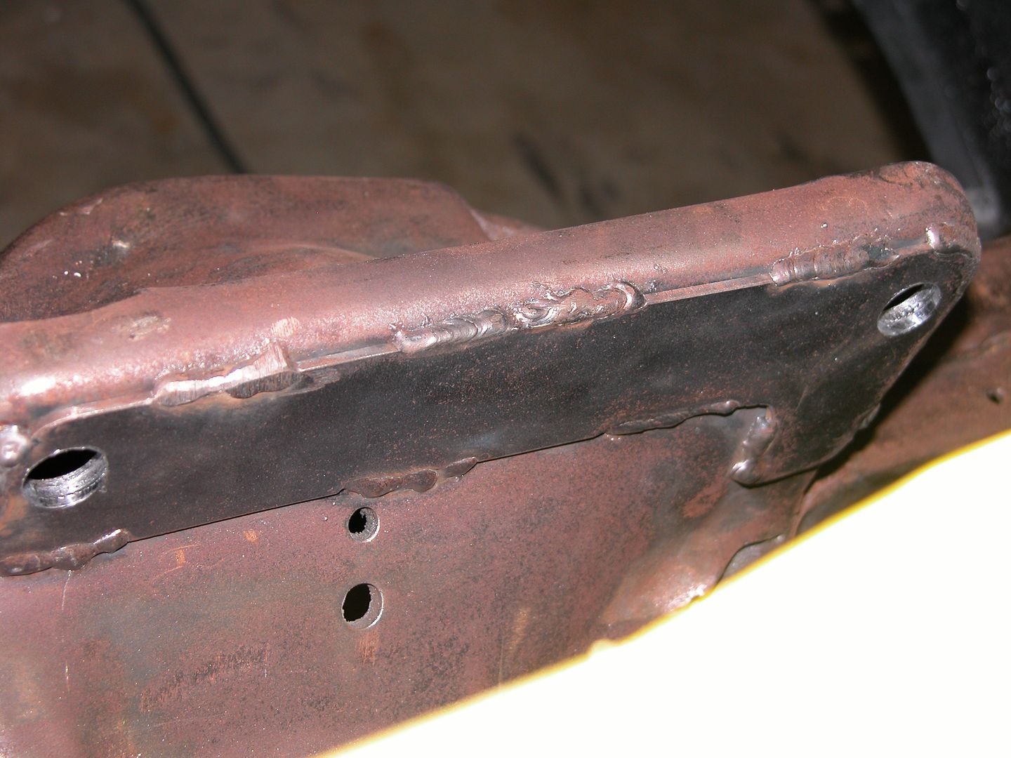 [/URL]
Pic below shows the difference between a stock mounting bolt for the UCA shaft and an ARP wheel stud used to replace them. You can see how the wider deeper spline section will support the bolt more rigidly.
[URL=http://s240.photobucket.com/user/NOTATA/media/The%2014%20Car%20Performance%20Therapy/002_zpshozi0tbe.jpg.html]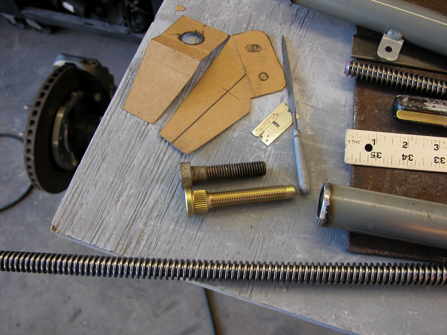 [/URL]
Pic below shows how the additional upper supports are attached to the PTFB Gen II adjustable G-braces and the angle of the lower support that is attached to the UCA bolt and sub frame.
[URL=http://s240.photobucket.com/user/NOTATA/media/The%2014%20Car%20Performance%20Therapy/007_zpsqojkvh2v.jpg.html]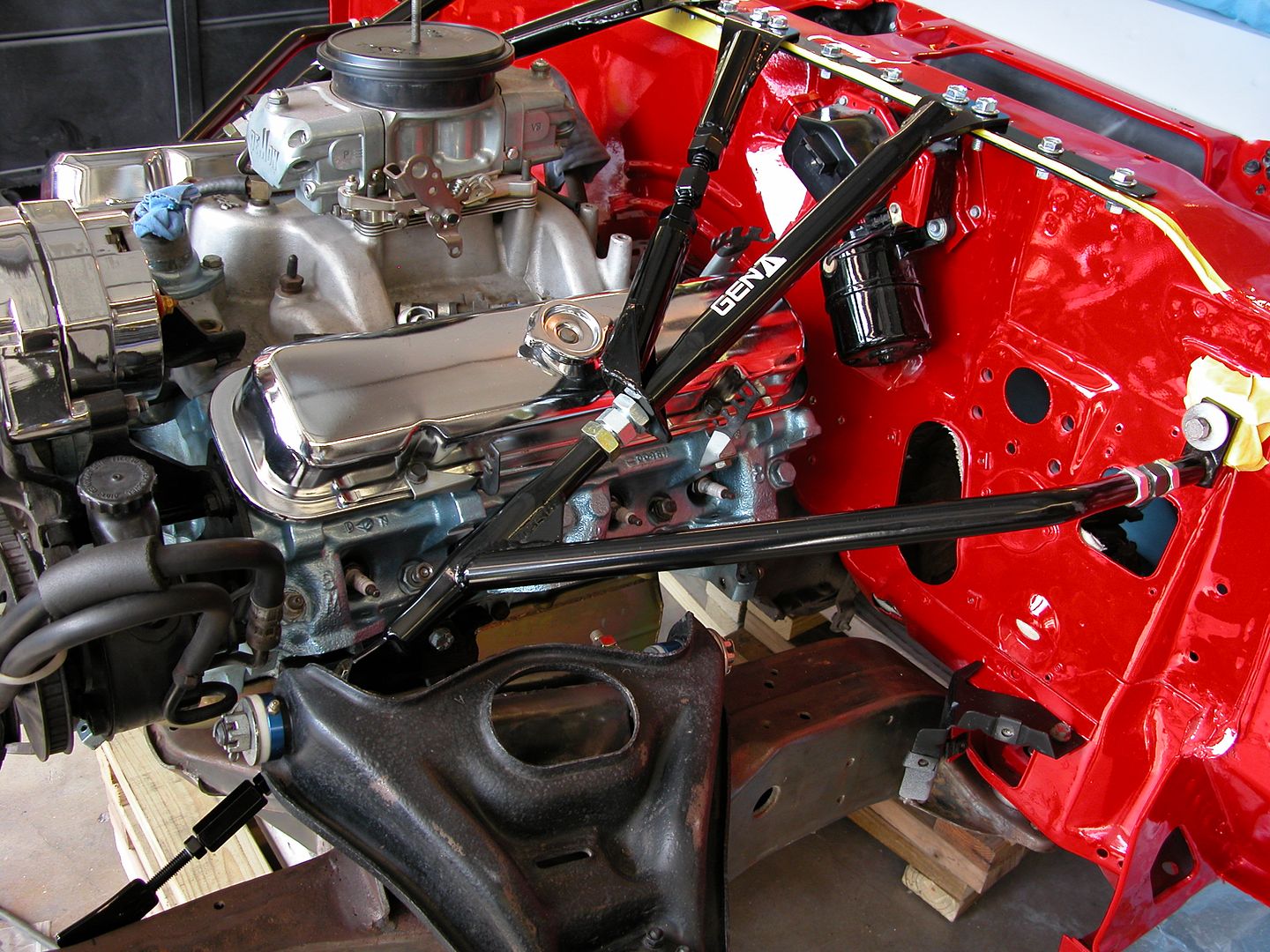 [/URL]
Pics below show the drivers side lower support. The unused mount on the steering box has to be cut off to provide clearance for the mounting bolt through the frame. I used 1/2" mounting bolts so I'd have a wide surface area which need to be ground down a bit for steering box clearance. Everything's close but fits. Careful marking of where the frame mounting bolt hole needs to be is critical on the drivers side. Passenger side there's plenty of room.
[URL=http://s240.photobucket.com/user/NOTATA/media/The%2014%20Car%20Performance%20Therapy/012_zps0ropnunl.jpg.html]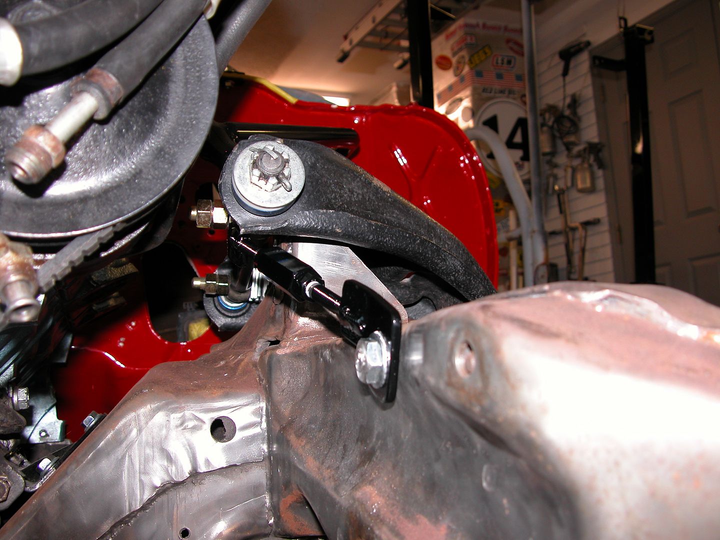 [/URL]
[URL=http://s240.photobucket.com/user/NOTATA/media/The%2014%20Car%20Performance%20Therapy/002_zpsgrgy5mkp.jpg.html]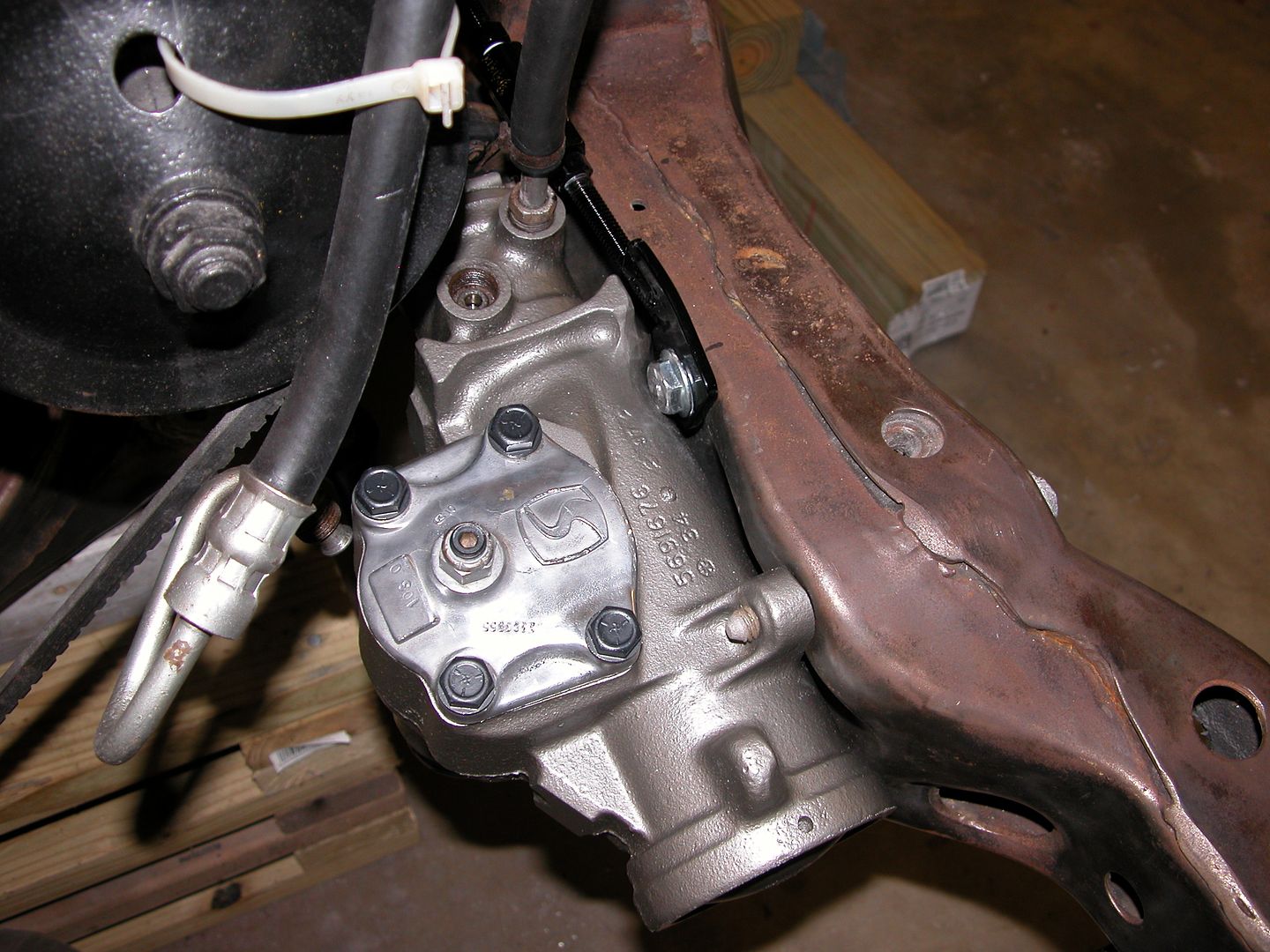 [/URL]
Pic below shows all the pieces used for the upgrades described that do not come with a set of PTFB Gen II adjustable G-braces.
[URL=http://s240.photobucket.com/user/NOTATA/media/The%2014%20Car%20Performance%20Therapy/010_zpsnih6odon.jpg.html]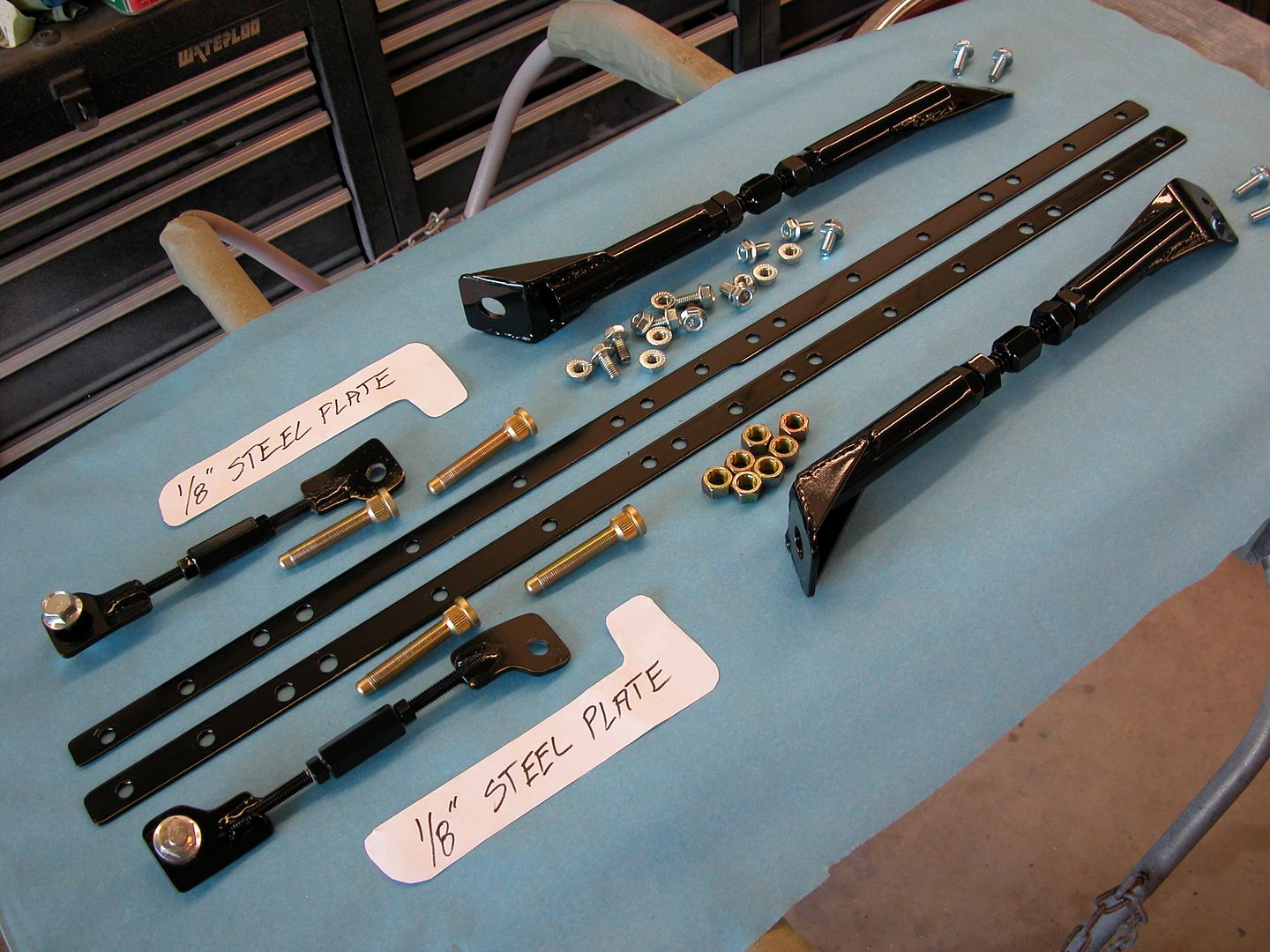 [/URL]
Interesting and informative post. I assume the brace needs to be removed in order to take the valve covers off?
Didn't try the valve covers but I don't have to readjust valves on a regular basis anyway and I'll probably have to make braces that are higher when I build the new engine anyway so I'll make sure I can removethe covers when I make new braces.
With everything mocked up and the last welding done to the sub frame I sandblasted it. Followed the blasting by shooting it with epoxy primer then regular high build primer followed by sanding then gloss black acrylic enamel.
[URL=http://s240.photobucket.com/user/NOTATA/media/The%2014%20Car%20Performance%20Therapy/003_zpsxuklmrhs.jpg.html]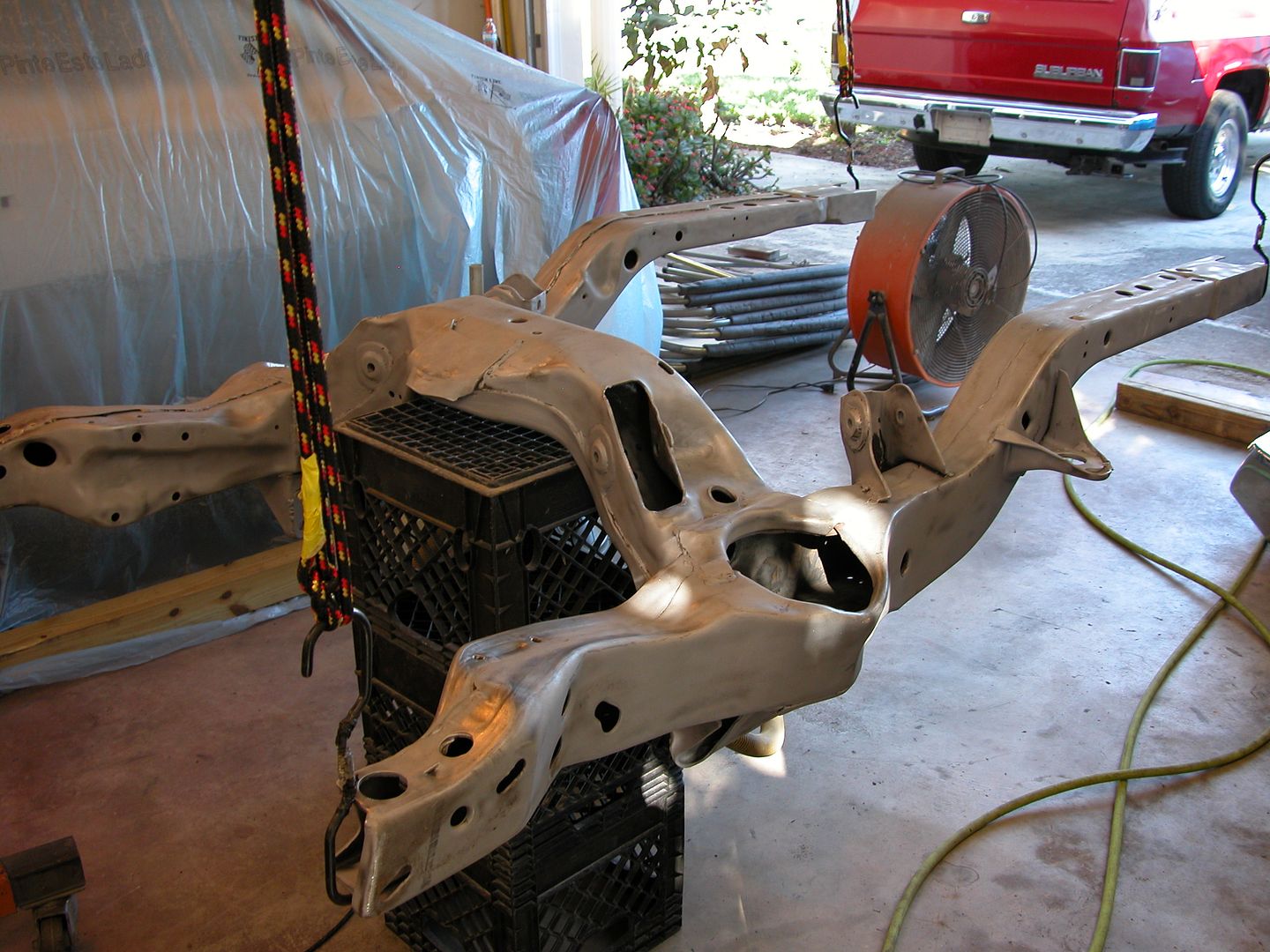 [/URL]
[URL=http://s240.photobucket.com/user/NOTATA/media/The%2014%20Car%20Performance%20Therapy/005_zpsakvigpja.jpg.html]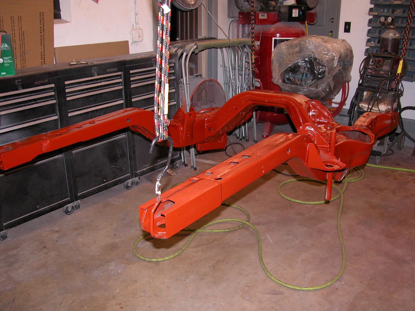 [/URL]
[URL=http://s240.photobucket.com/user/NOTATA/media/The%2014%20Car%20Performance%20Therapy/008_zpshdcbzdyw.jpg.html]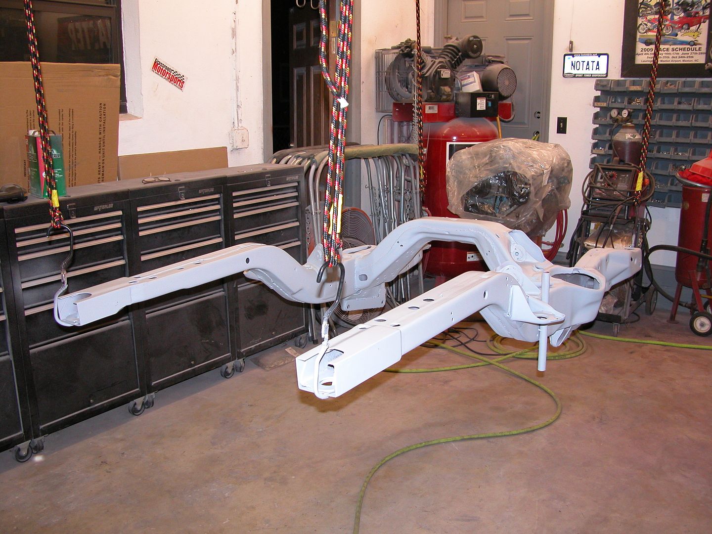 [/URL]
[URL=http://s240.photobucket.com/user/NOTATA/media/The%2014%20Car%20Performance%20Therapy/001_zpsibnike74.jpg.html]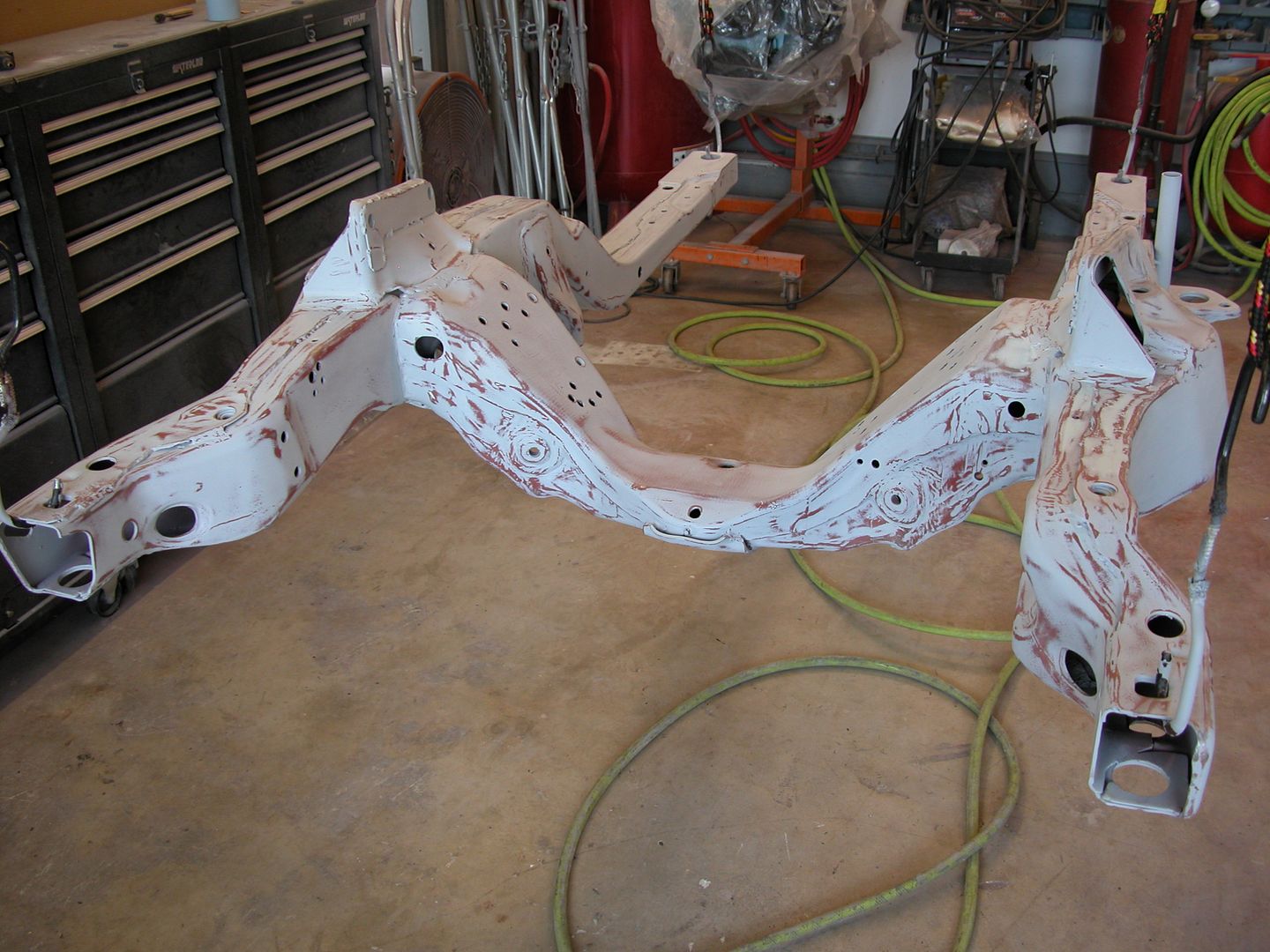 [/URL]
[URL=http://s240.photobucket.com/user/NOTATA/media/The%2014%20Car%20Performance%20Therapy/002_zpspn78b2na.jpg.html]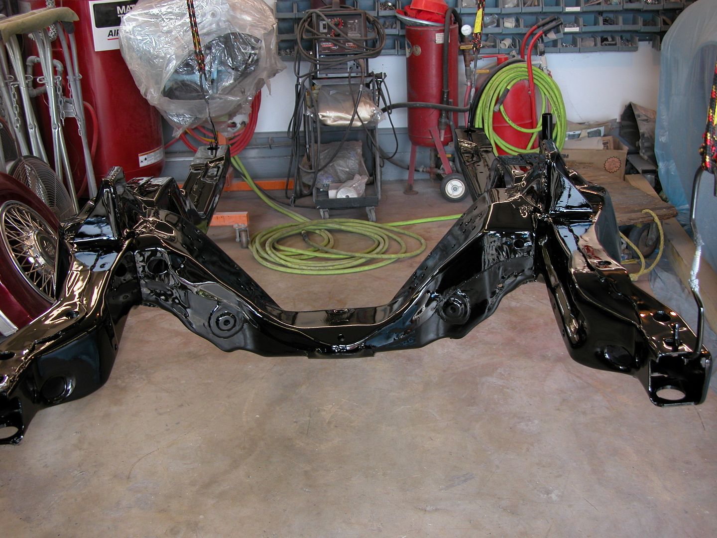 [/URL]
When I had the roll cage in my car fabricated 7-8 years ago I removed a lot of the interior, took the car to the fab shop where they built the cage, and then I painted the cage and reassembled the interior. I spent a lot of time trying to mask off the dash, headliner, and other interior bits that hadn't been removed so I could spray the cage. I found it extremely difficult (OK impossible) to get everything masked off and try to figure out a way to spray the cage with the windshield and rear window in the car. It just couldn't be done. So I ended up painting the cage with a brush Using PPG DBI (base coat with activator) then sanding the brush marks smooth, then sanding, then painting, then sanding, and painting again until I had several coats on. The DBI is for use without a clear coat. It came out fine overall but it just didn't look the way I envisioned at the start. There were brush marks and other little things I'd notice that bugged me although probably no one else ever noticed with all the roll cage padding etc. in place.
Since I've got everything out of the car except the headliner (bow type), shifter, and some wires this was the time to spray the cage since the dash windows etc. are all out. So I sanded down the previously applied paint and shot it with the same color PPG Deltron Silver Frost base coat followed by PPG Global Matte clearcoat. For those of you who've never painted a cage, it sucks. I don't remember it being any easier when I was 40 years younger and although I'm still slender and agile, a contortionist I am not. However the cage came out the way I wanted it to the first time and I'm happy with the results.
[URL=http://s240.photobucket.com/user/NOTATA/media/The%2014%20Car%20Performance%20Therapy/004_zpsjtnw7roo.jpg.html] [/URL]
[URL=http://s240.photobucket.com/user/NOTATA/media/The%2014%20Car%20Performance%20Therapy/005_zpscsrxrkno.jpg.html]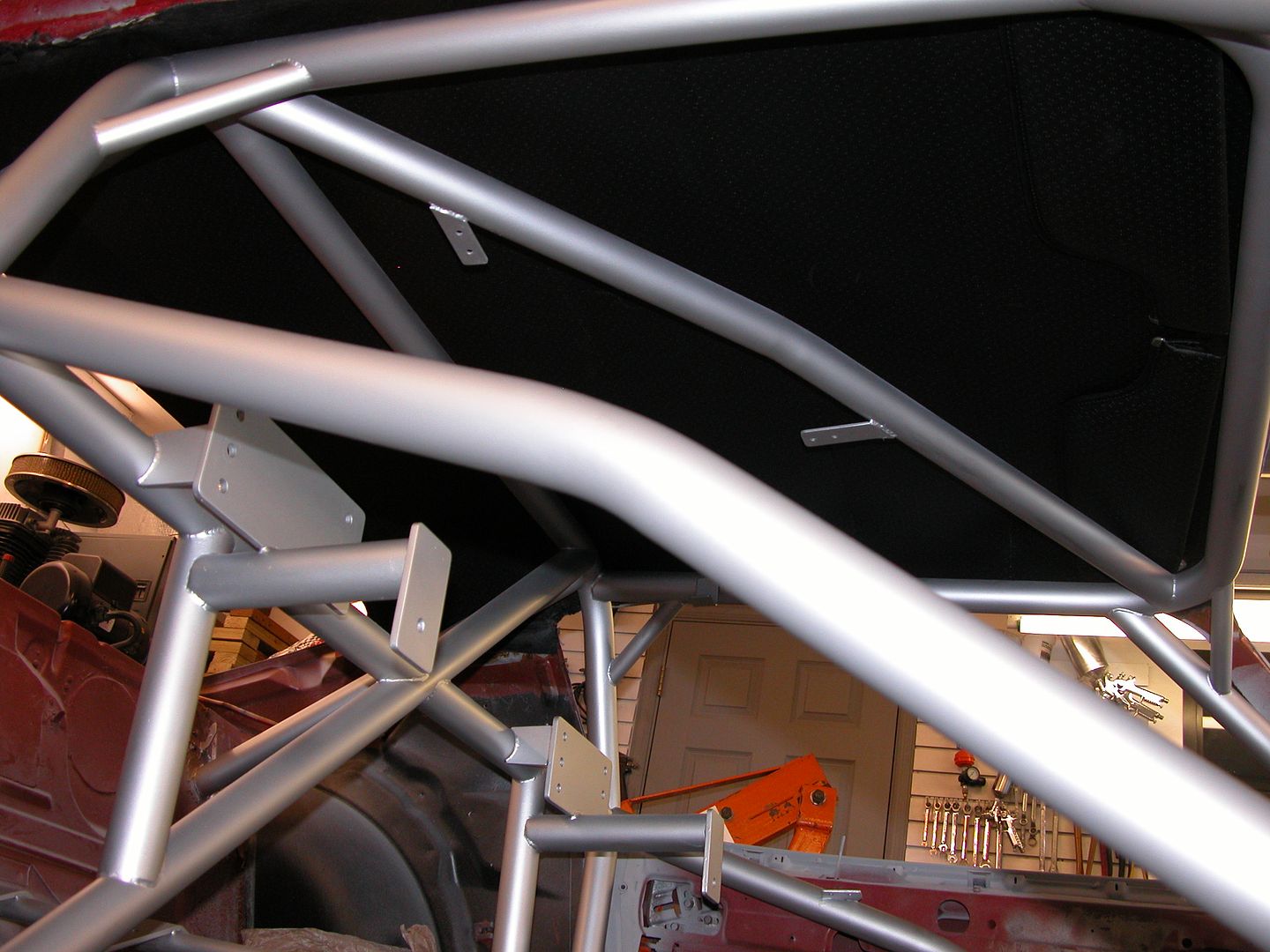 [/URL]
That looks great. Your finishing skills continue to amaze me. I can fab E36 M3 all day long, but my finish work is severely lacking.
Thanks Dave! It's time consuming to do all the finish work. It would be soooo much faster to do this build if it was just a track car. Here's a perfect example.....
I'm finally nearing the end of bodywork and paint prep. Got the doors in final primer which were the last big parts of the steel body panels and am currently sanding all of the small pieces that are in final primer (about 50) to be ready for sealer/paint. There's lots of different materials used in the construction of all the smaller pieces. Cast metal, stamped steel, various types of plastics, fiberglass, and the Endura bumper. The bumper caused me lots of lost time and materials.
The first time I painted the car 25 years ago I used 3M flexible material repair products followed by the old type lacquer primer followed by epoxy primer and top coated with acrylic enamel. Worked great and still looks good on my original bumper. I bought a new (used) bumper about 20 years ago with the intention of modifying when I got around to it, which is during this rebuild. The bumper had several layers of primers and paints over the the original paint. It was all cracked and crappy looking so I blasted and hand sanded it to bare Endura.
I modified the bumper by filling the bumper jack slots and trimming the lower lip and then proceeded to use the modern version of the 3M flexible repair material to repair lifting Endura and make it smooth. Then primed with PPG K-38, blocked, primed, and blocked till it was straight with very little primer on it. Then laid a couple medium wet coats of K-38 reduced for final prime and set the bumper aside to allow materials to shrink back while working on other parts. Knowing the bumper was going to get flexed moving it around off the car while working on it I used a flex agent in the primers to slow down full curing. When final primed I put the bumper in a safe place in the house to allow full curing and shrink back.. A year or so later I pulled it out to mock up all the front end sheet metal on the car and the "final" primer was all cracked.
I asked at my local paint supply store where I buy all my materials and they had no real positive answer as to why the final prime cracked. I'd gone through the same procedures with lots of other flexible parts for this car as well as modern cars and never had the final prime crack. The only difference was the use of a flex agent. SO, it was time to start from scratch.
I stripped off all the primer and repair materials I'd put on the bumper and proceeded to go through the process all over again. Those of you who have sanded Endura bumpers know this is not fun at all because for some weird reason it seems to take twice as long to sand anything on an Endura bumper. This time the bumper was on the car with all the front end sheet metal aligned so I could work it so the panel alignment from bumper to fenders and hood was nice and smooth sanding across the panel gap. I did not use any flex agent in the primers and used PPG Omni primer for the blocking coats to reduce cost a bit then used K-38 reduced for the final prime. It looked perfect, so I set it aside in the house to shrink back and fully cure. I moved on to the G-brace mock up.
Several months later I needed to move the bumper out of the house overnight so I stuck it in the garage. In the morning I went to retrieve the bumper and found the cracked primer you see in the pics below. GRRRRRR! So I put the bumper in the truck and zipped up the street to the paint store. They related that a restoration shop they supply was having the same problems on a GTO Endura bumper. A quick internet search showed that others had similar problems when using the modern high fill primers like the PPG Omni and K-38. The general consensus is not to use a high fill but rather an epoxy primer for blocking sanding etc. on Endura. So I sanded all the primer off by hand then sprayed it with PPG DP48LF epoxy primer the paint store guys gave me for free because they felt bad and knew how much time and materials I already had in the bumper. It's now almost ready for "final?" prime with reduced epoxy primer.
Apparently the thin Lacquer primer and epoxy primer I used 25 years ago was fine but the Endura bumper expansion/contraction rate is different enough from the rate of the high build primer that it causes the cracking? We'll see...... Tough lesson as I now refer to it as the $3,000.00 bumper because I've got over 100 hours in it plus a couple hundred dollars worth of blasting media, panel bond, flexible repair material, and many coats of primer that ended up on the floor. K-38 is 300 bucks a gallon!
So here's the pics. I put some dry guide coat magic dust on the cracks so you can see them in the pics. If it doesn't work out this time I'm gonna buy a fiberglass bumper. Last pic is blocking out the final prime on the shaker scoop, most of the other small pieces are done with blocking and ready for sealer/paint!
[URL=http://s240.photobucket.com/user/NOTATA/media/The%2014%20Car%20Performance%20Therapy/001_zpsblamvemk.jpg.html]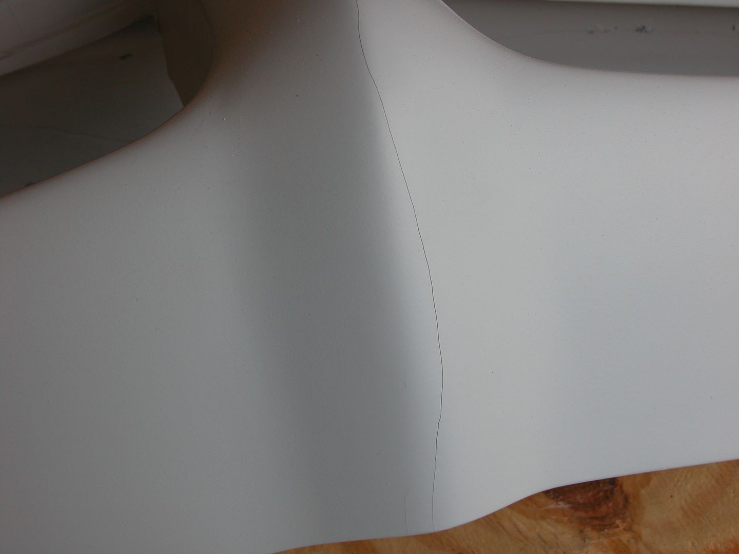 [/URL]
[URL=http://s240.photobucket.com/user/NOTATA/media/The%2014%20Car%20Performance%20Therapy/002_zpspm4av833.jpg.html]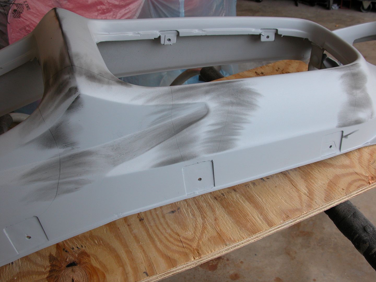 [/URL]
[URL=http://s240.photobucket.com/user/NOTATA/media/The%2014%20Car%20Performance%20Therapy/001_zpstwy0kgbo.jpg.html] [/URL]
[URL=http://s240.photobucket.com/user/NOTATA/media/The%2014%20Car%20Performance%20Therapy/003_zpsm1pnok2w.jpg.html]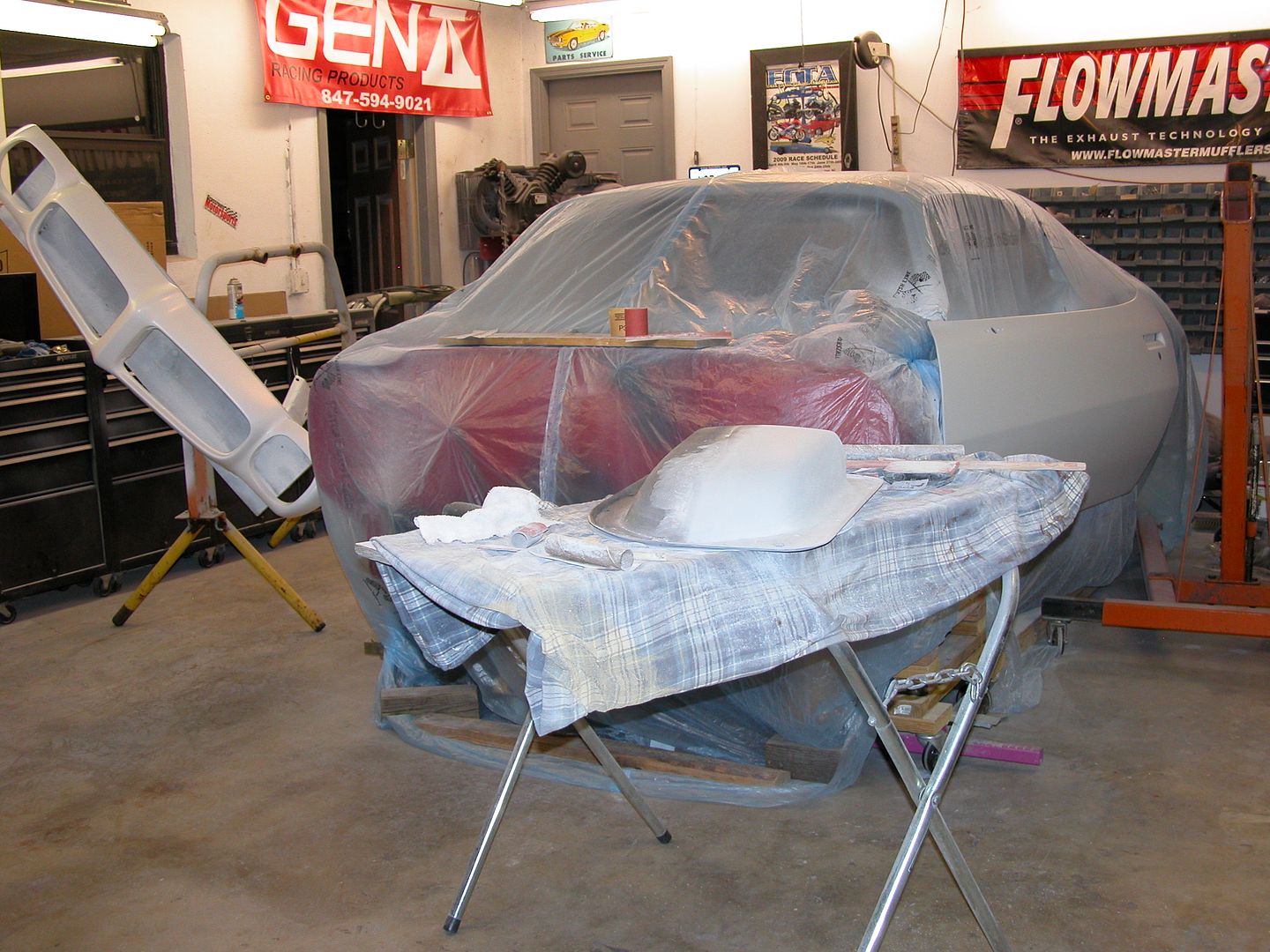 [/URL]
I'd blocked out the front fenders for final primer and set them aside when I took the front end sheet metal off to work on the engine/trans and G-brace mock up. I didn't want to mask off everything since the cowl and cage are already painted and the fenders were coming off anyway. Finally got around to shooting the last coat of primer on them today. Will start blocking out the final primer on the major body parts for sealer and paint soon.
Meanwhile I've got all the smaller pieces ready for sealer. With all the extra pieces like the multiple sets of fender vents and rear spoilers I've got about 50 small parts that need to be body color.
As if I didn't have enough paint work with body color parts I've also been prepping and painting other parts like the hood hinges, under tray supports, inner fender extensions, etc.
[URL=http://s240.photobucket.com/user/NOTATA/media/The%2014%20Car%20Performance%20Therapy/003_zpsyb9kjxt7.jpg.html]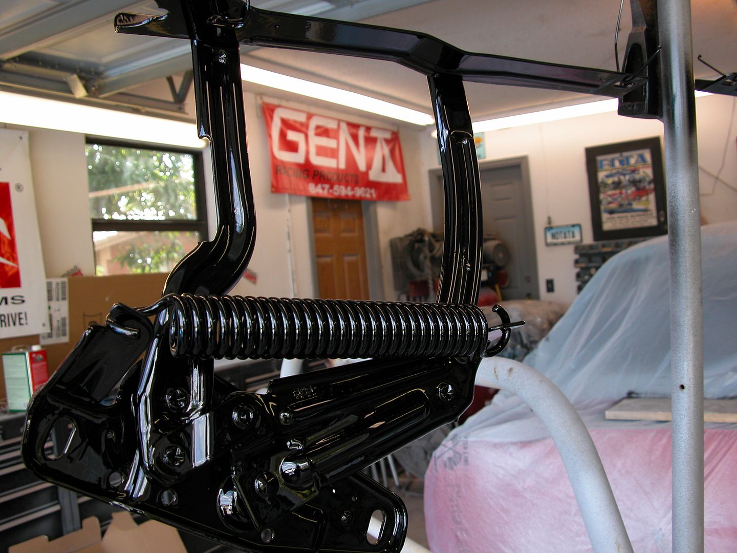 [/URL]
[URL=http://s240.photobucket.com/user/NOTATA/media/The%2014%20Car%20Performance%20Therapy/011_zpsrwjiohmo.jpg.html]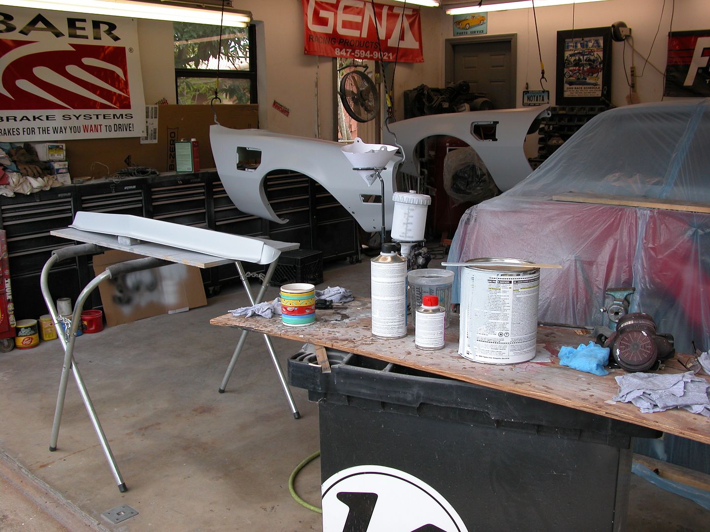 [/URL]
[URL=http://s240.photobucket.com/user/NOTATA/media/The%2014%20Car%20Performance%20Therapy/014_zpstkugvfzl.jpg.html]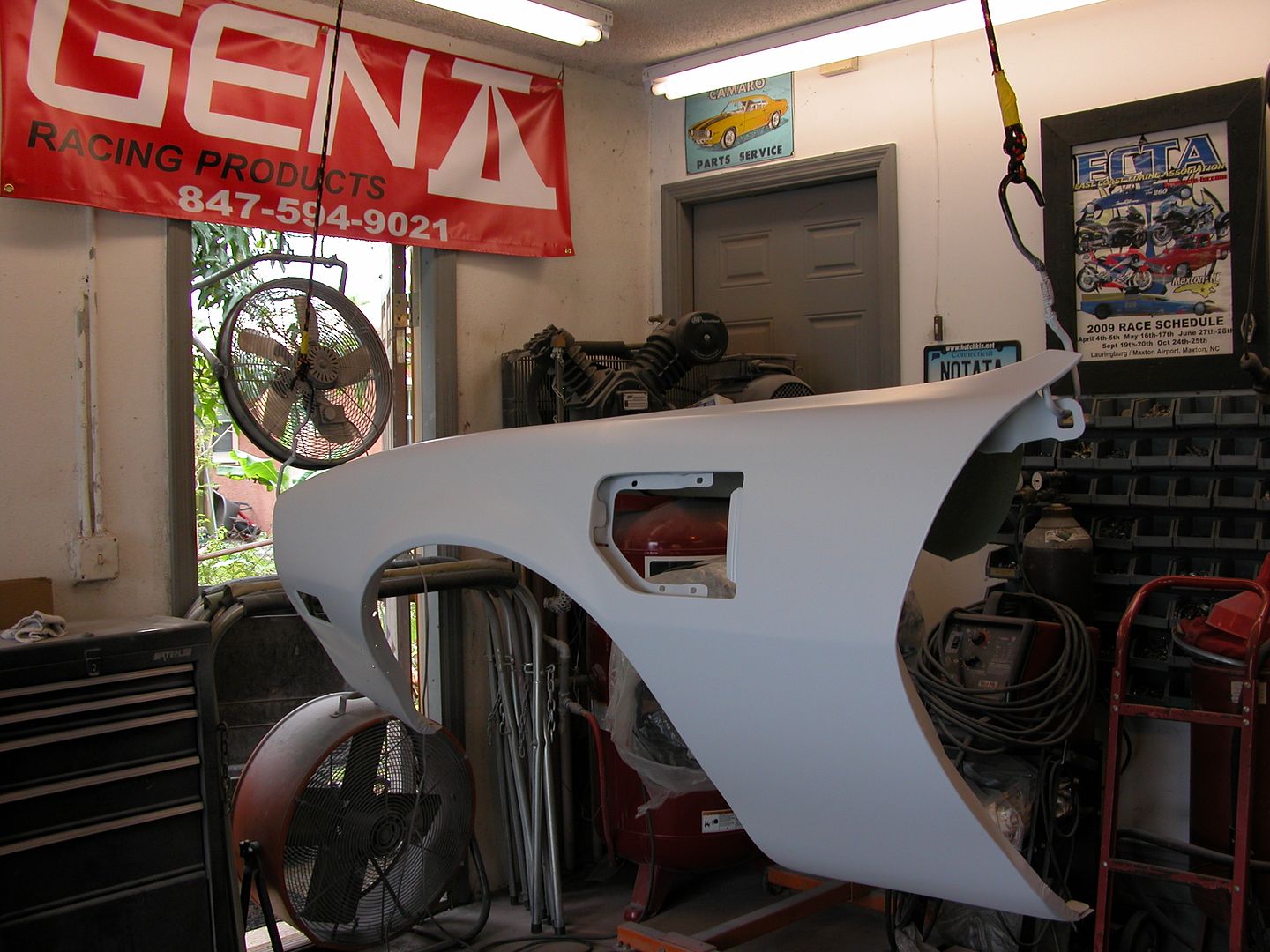 [/URL]
Thanks! Maybe too patient? Can't wait to get it back on track! Spent a lot of hours just on these smaller pieces. They were all sand blasted, stripped by hand, or made from scratch. Then they got primed, filled, block sanded, primed, and block sanded again at a minimum before getting on the bench. Most of them are ready for sealer next.
[URL=http://s240.photobucket.com/user/NOTATA/media/The%2014%20Car%20Performance%20Therapy/002_zpse75bdh2n.jpg.html]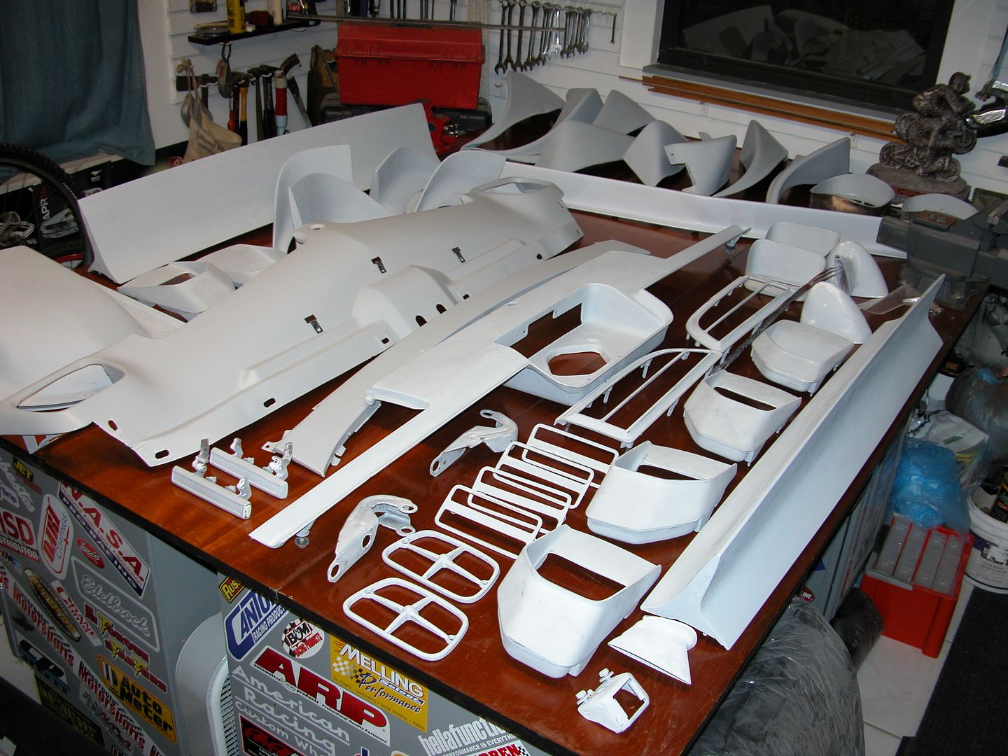 [/URL]
Shot some body color on the inside of the fenders today. Then once the paint flashed over I put them in the South Florida natural solar baking area. Will bake them some more tomorrow.
[URL=http://s240.photobucket.com/user/NOTATA/media/The%2014%20Car%20Performance%20Therapy/003_zpsqtgk4my8.jpg.html]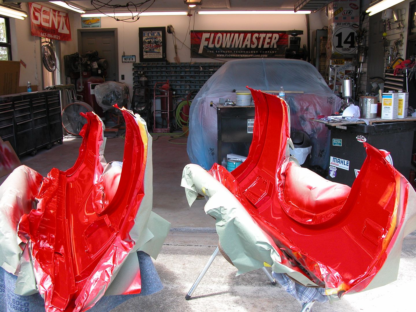 [/URL]
[URL=http://s240.photobucket.com/user/NOTATA/media/The%2014%20Car%20Performance%20Therapy/006_zpsx4wbuxvj.jpg.html] [/URL]
You'll need to log in to post.