As I start roughing in a design for the intake of the LS4.9, I'm wondering what I need to factor in in order to have this thing work correctly.
Questions I have:
What am I missing?
Rough design, way past the 70% of engine displacement figure.

In reply to californiamilleghia :
Maybe, but probably not. Nothing I can think of that is close enough to use without issues. The ports on this are roughly twice the size of the stock ports on the 300 head. I initially thought about chopping up and matching up the EFI intake, sort of make a sleeper where anyone that takes a quick look under the hood would just see the "stock" intake and not think anything past that.
In reply to Mr_Asa :
Intake length, diameter is a function of cam design. I simply put data into my Engine analyzer program ( commercially available ) and play around until the power curve is to my liking.
Air has mass, any time you force it to change direction (curves bends) you slow it down. The more sharp the direction change the greater the loss. The longer the tube the greater the loss.
Like any mass, starting and stopping takes energy and time. So the most effective approach is when adjacent cylinders fire 90 degrees from each other. The motion of intake from one cylinder transfers to the next with a minimum of loss. If it's adjacent and 90 degrees different. ( remember, intake/compression/power/exhaust )
The plenum needs to follow the Helmholz principle if turbocharging. That always requires precision casting to work.
I used to have a book that was really good for this topic but I loaned it an ex-roommate and... we all know how that goes. I can't even remember the name of it.
There are formulas for how to decide your runner length and your runner diameter based on where you want your power to be accentuated.
For reading on this, I'd start with Four Stroke Engine Tuning by A. Graham Bell. I'm also pretty sure that Paul Van Valkenberg might have something useful in his book on race preparation, but it has been a few years since I've had it off the shelf...perhaps I'll try to dust it off this week and confirm.
In reply to ae86andkp61 (Forum Supporter) :
You remind me that I've got a few David Vizard books squirreled away somewhere that I should probably revisit. I'll check them and see what I have there.
First off, it's complicated. Anyone that tells you it isn't is trying to sell you something.
Boosted engines usually can make a broad enough powerband with the right choice of parts you can make some concessions in intake design that will not be felt as much as NA.
That being said think of the plenum as a reservoir, at 100% VE you would use half the displacement per rev of that air. Obviously you aren't 100% at least not across the rev range, but you may be over that if you make some other choices in design or run the engine forced at speed (over 100mph we see MAP over 100kpa quite often) so going to 70% of displacement doesn't seem like a bad place but we have used up to 2.5x without a downside. One thing about large plenums we see is not as much reliance on throttle size to hit max power. With smaller plenums we usually need as big as we can fit, and with the big plenums we can use ones that are a bit more driveable. Not that much I do is driveable!
On intake length the calculator and bgsoflex.com works really well in finding 1/2/3 harmonic, usually 1 is way too long to fit so some design for 2/3 works out well. I have seen staggered runners help make broader power than equal length, another consideration. Also bellmouths or at least a radius on the runner inlet I would say is required, at the very least smoothed. We did some back to back testing on that and it was worth 7% on the dyno with no other changes. Flow bench will show even more but those are sensitive.
Some people say you need taper as you show.. I am not convinced but it may be important if the plenum is very undersized. Remember the reservior, if the air has to make a 90deg turn do you want for it to happen while the air is moving slow, or fast?
Infinite plenum volume starts to act like ITB in a way, but there will be a practical limit in packaging, etc. Generally that's the most limiting factor.
I will edit later with a pic of my intake on my 3.6 - placeholder.
In reply to Paul_VR6 (Forum Supporter) :
I don't think that website works. I can't find anything on there for a intake length calculator at least.
Did you make it to this site?
https://bgsoflex.com/auto.html
I saw the "bgso" and knew I remembered it from early Megasquirt days.
You have to right click on links and "open in new window"
Mr_Asa said:No, it didn't link to that site at all. That one looks helpful
I got this:
Not sure I typoed or what http://www.bgsoflex.com/intakeln.html is the one I have used (edit your pic just came up, the menu/links don't work anymore and I had to google into the intake calculator)
In reply to Paul_VR6 (Forum Supporter) :
I see what you mean about the first harmonic being too long.
It'd be nice if they did one from the opposite end, with the RPM being able to be dialed in and it spit out the lengths you'd want.
It would be nice but I did an exercise where I iterated by the inch and put them into excel. I can't find it now of course but I ended up with 14" to the valve and if you look at my dyno the bumps in the curve are within 100rpm of the calcs
I was going to ask a friend in IT to see if they could use developer tools to look inside the website and dig up the mathematical formulas so I could make an excel sheet from them. If not I was going to do the same thing you did.
Cut up and reuse parts of this OBX Racing Aluminum Individual Throttle Body (ITB) Fits Chevy Corvette Z06 LS7 | eBay
Would be sweet!
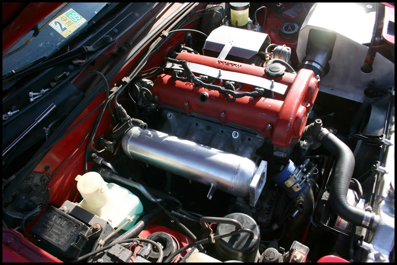
The biggest thing with fabricating an intake is the radius into the runners. None is junk, big is good. Look at ported Honda intakes for an idea of how big those go in order to maximize them. I personally wouldn't get into over engineering an intake. Stick to the simple good things like 6-12" runners with generous radius into the plenum, 3 or 4" tall plenum, tapped to the back with TB at the front (reference 2JZ and RB intakes) and a mid size throttle body. That should all get a decent-good performing intake, reasonable fab work, and not go horribly wrong.
Figure out optimal intake length (you'll probably be limited by engine bay room) and look for existing manifolds that have similar port spacing.
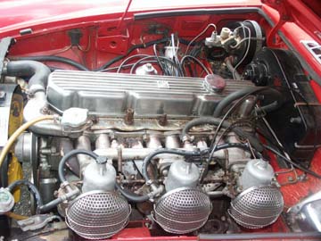
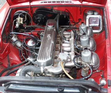
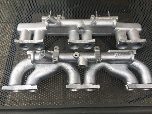
I custom built this tricarb MGC intake using chopped up TR4A intakes (1 1/2 of them) heliarced together and properly ported to suit. Huge power gain and it looks like a factory intake!


Stock (horrid) intakes (home market had a different one than North American export cars):

Calvin Nelson had a thread about building an intake for a 4200 Vortec. I think that would be worth looking at. The power numbers he's made with that setup seem like a good target for the LS 300 you're building.
How's that build going anyway? I haven't seen that thread come up in a while.
Do whatever is easiest and get it running, then tweak and rebuild from there.
Personally Id get an intake flange, make runners in whatever shape and length I need for packaging (length and tuning be damned), weld them to a large cylindrical plenum, cut it open and weld velocity stacks at the beginning of the runners, then pick my throttle body and weld a flange for it on the end of the can. Done. Once its running, dyno it and then decide if I feel like building another one.
My thinking is I would spend forever trying to build a theoretically perfect intake, then deal with packaging on top, only for the next step to be an equally large project and Id never get done. All in hopes of trying to extract every last hp or whatever. Id rather build a quick and dirty one, that works, and is decent, then once its running I can see what my priorities are. Did I leave 2hp on the table with the intake? Who cares. Your kind of in relatively uncharted territory, Id be worried about broad stroke things, not fine tuning.
Ala Brain's intake on MT


I think his is still a cast base though, so obvisouly some ovaled piping for runners and fabricated flanges and lots bigger
I was planning on casting this myself. I can radius the interior fairly easily. Here's what I have on there right now, a 1/2" radius I think? I could go up to a 1 or 1.5" radius.

In reply to Mr_Asa :
That fuel injector area (the pointy area I assume you copied from the head) is not going to cause problems at the plenum. A transition to oval/round or just a rectangle with radius corners would be better. I'd consider 1/2" radius into the plenum as a bare minimum. Some Honda manifolds that work awesome are bellmouthed/velocity stacked out to double the port size if not more.
What's your plan to cast it? There could be manufacturing limitations to work around...
A fab technique I've seen for the radius is bending a round stock of aluminum into a doughnut then welded to a round tube. The other end of the tube gets bent/shaped to fit an opening in the flange. Flange gets ported/shaped to finish the transition. I've seen this for 4 valve type heads where the ports are typically oval so starting with a round tube is an easy transition.
You'll need to log in to post.