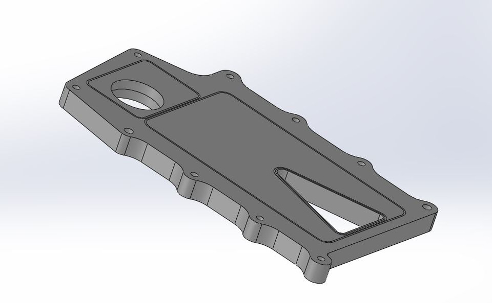
So i have a plan to put a m122 supercharger from a GT500 onto the 4.8 in my 300zx. I found a cad drawing someone made for a flange to bolt the blower to that i can then weld to the top of a LS fabricated manifold. I am looking to have this plate made for as cheap as possible. I've gotten one quote from a guy i went to college with that now builds SEMA quality cars and bikes and got quoted $500-$750, im hoping thats not the going rate for something like this and he just charges high because of the kind of work he does.

This is the plate that im wanting made, i know in the drawing it's a 1" plate which i really dont think it needs that thick, im thinking more like 1/2" will be good enough and help reduce material cost. Also the round hole is tapered which adds complexity to the machine work, for simplicity that hole can just be cut to the larger diameter all the way through, I don’t need it to be tapered. It could also be just made as a large, rectangular plate rather then the curved edges between bolt bosses. I'm willing to change anything on that to help reduce the overall cost. I dont have any CAD software and wouldnt know how to use it if i did so i cant make any changes to it.
If anyone here is able to look into having this made or can put me in contact with someone that would be awesome. like i said i really want to spend as little as possible for this. I can send the STEP file to anyone to check out if they dont want to sign up on the linked website to get the file.
I'll start by asking why do you want that to be CNC'd in the first place. There is absolutly no high precision requirements for that plate. You could simply print out a 1:1 copy and cut this by hand. Or go with your local laser/water-jet cutter. With the prices they give me locally, I don't bother making brackets by hand anymore.
+1 for looking into water-jet or laser cutting. Check out this guy for help with the CAD:
https://grassrootsmotorsports.com/forum/grm/cad-services/135592/page1/
Yeah - I would watch some "Project Binky" and the like - CAD (cardboard aided design) and the like will go a lot further than you think. I've seen several Lemons racecars wtih superchargers strapped on using various amounts of angle-grinded metal and willpower.
https://www.youtube.com/user/badobsessionmsport
If those are grooves for o-rings to seal the blower to the plate, there are some accuracy requirements there. You could cut out the basic shape and have someone with a mill take care of that for you. It also has to be very flat.
In reply to Keith Tanner :
yes those grooves are for o-rings which i dont have to use but it would be more ideal to keep them.
My backup plan is to do a hand made piece but i figured since there was a drawing available i figured it was worth a shot to see if i could get it made for a decent price.
is emachineshop still a thing?
Are you looking to weld this to a hand made intake or is there one out there you’re trying to adapt to? My search history has lots of m112 and m122’s in it from the last few days and it appears we’re thinking the exact same thing
If the plate is machined first and then welded, I would be concerned about keeping the mounting face flat. Might need to rough the openings, then weld, and finally machine the mating face and holes.
email me the CAD file I can see about editing it for you.
Email me the file and if I have the material I’ll make it for you. If I don't have that size you can buy it and send it to me.
In reply to Slippery :
This sounds like the droid you are looking for OP.
I was going to offer to cut the holes and outline for cheap on my Plasma table but a waterjet or mill is WAY better than I can manage.
In reply to Patrick :
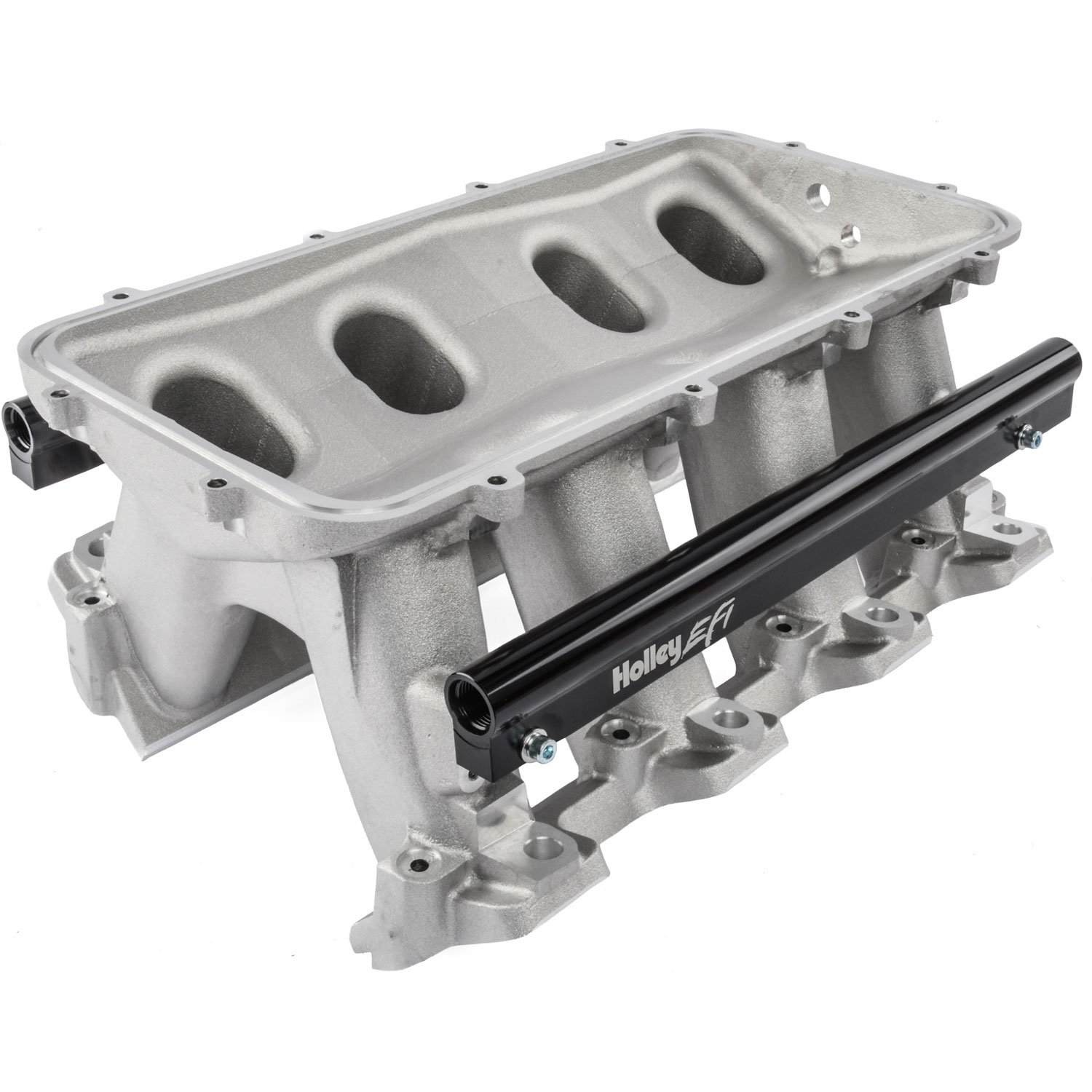
I plan on putting it on top of a Holley hi-ram lower intake:

the plan is to weld the supercharger plate to this plate which will bolt to that lower intake:

In reply to dean1484 :
That would be awesome! thinking about it more it would really be easier if it was a rectangle piece to fit over the hi-ram lower intake i'll be putting it on.
In reply to Slippery :
Once i get the drawing back from dean1484 i will send it to you
Also i think one of you emailed me about sending this to you. the email address contains 'pilot' in it
In reply to Slippery :
Once i get the drawing
Also i think one of you emailed me about sending this to you. the email address contains 'pilot' in it
That’s my email. Send me the file as is, I can modify it. I want to look at it to see how big the part is and what am I getting into 
Why do you want to weld the machined plate to that other piece? Can’t you design it so that the machine plate attaches to the manifold directly?
If you need that lower piece reversed engineered I have a CMM we can use to do that.
I was going to say if you had the cad for teh 2nd plate or the measurements of it I could just make it a one piece part in cad. the only thing that would need to be dealt with is pulley alignment so the aligment of the two pieces would be critical. WAIT. .. Thinking about this you would need some sort of air box/space under the suppercharger. You may get funny air flow distribution to the cylinders with out it.
For that second piece all I would really need is the bolt hole placement. they look like a symmetrical grid so that would be easy and then some measurements off the intake
dean1484 said:
I was going to say if you had the cad for teh 2nd plate or the measurements of it I could just make it a one piece part in cad. the only thing that would need to be dealt with is pulley alignment so the aligment of the two pieces would be critical. WAIT. .. Thinking about this you would need some sort of air box/space under the suppercharger. You may get funny air flow distribution to the cylinders with out it.
Never mind I see that the intake is sloped towards the center. I did not see that at first. Carry on

If I made it in one piece I would use studs in the intake and then studs in the adaptor plate to hold the supercharger. I think the adapter place is going to have to be reasonable strong due to the tension of teh belt. How long is the snout on the supercharger? Also I would have concerns that the small size of the studs on the manifold will not be strong enough to take the pulling forces applied by the belt pulling down on the snout. The longer the snout this more this is going to be a problem. I worry that even if you used grade 8 hardware that the physical size of the threads and the material that the intake is made out of is not strong enough. (It looks to be just cast aluminum) You would rip the studs out at the rear edge where the pate mounts to the manifold. This may be a case where you really need to make the plate up and then tig weld everything together to the intake and then bolt on the supercharger. If you do this you are going to need to get the alignment of things perfect so the belt is in alignment with the crank.
In reply to dean1484 :
How much tension do you think is on that belt in order to pull the bolts/studs off the plate?
The belt Tensioner is going to be at an angle and Not pulling Straight Down. the reason for it is because as it spins Faster it becomes Looser not tighter
Slippery said:
In reply to dean1484 :
How much tension do you think is on that belt in order to pull the bolts/studs off the plate?
Not enough info to figure that out. If you could add a brace at the back of the supercharger that attached to the block things would be much better.
I own a supercharger that attaches to the engine with 6 6mm bolts. The supercharger plenum and the manifold it attaches to are cast aluminum. There is a second bracket that supports the snout and bolts to the accessory mounts. In my case, the supercharger hangs over the driver's side cylinder head, rather than being centered between heads like it would be in this case, so there are some additional bending forces at work that edizzle wouldn't encounter. If it turns out that the load would be too much for a dozen bolts on the manifold, perhaps another bracket could be made to support the supercharger snout?
Not trying to be a smartass, but I think you guys are overthinking this. You are looking at failure points and while you have no idea what the bolts can take, I bet its more than you think.


