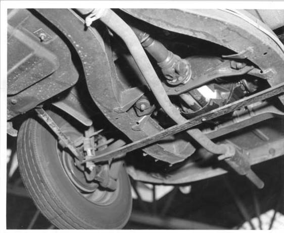
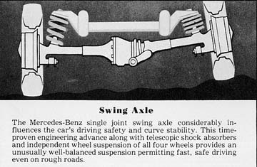
Roll Center on swing axle cars is generally accepted to be the intersection of the two lines from centroid of tire contact patch through the swing axle UJoint pivot center.
Let's use some simple trig to calculate the RC at zero camber, then at max compression, then at max droop.
Visualize right triangle ABC, where A is the centroid of the tire contact patch, B is the point on road surface directly under the RC, and C is the UJ pivot center. 90 degree between segment A-B and B-C.
Now visualize another right triangle CDE, where C is the same UJ pivot center, D is the midpoint between the two UJ pivot centers, and E is the RC.
Triangles ABC and CDE are similar, in the Geometric sense, i.e. both have same set of interior angles, and thus ratio's of sides are also proportional.
Let's plug in some actual dimensions, and get calculating!
Assume Spitfire track = 48", tire diameter = 24", and that UJ pivot center-center distance along diff axle centerline is 11"
(I just measured this on one of the several Spitfire diffs decorating my workspace).
segment A-B = 18.5" (half the 48" track, minus half the 11" UJ c-c distance)
segment B-C = 12" (zero camber, so UJ pivot center is same height as hub center, half the tire diameter)
segment A-C = 22.1" (Pythagorean formula for hypotenuse, rounded)
segment C-D = 5.5" (half of the UJ c-c distance)
segment D-E = 3.6" ( (5.512)/18.5, similar triangle, rounded)
segment C-E = 6.6" ( (5.522.1)/18.5, similar triangle, rounded)
Segment D-E is distance from diff axle centerline to RC.
So the RC height above road surface at zero camber = sum of segments B-C and D-E, about 15.6"
Now for max compression, assume that ground clearance is 5", so that's the compression limit, let's recalculate:
segment A-C = 22.1" (stays the same)
segment B-C = 7" (zero camber height minus 5")
segment A-B = 21" (Pyth, rounded)
segment C-D = 5.5" (stays the same)
segment D-E = 1.8" ( (5.57)/21, rounded)
segment C-E = 5.8" ( (5.522.1)/21, rounded)
Segment D-E is distance from diff axle centerline to RC, which moved 1.8", from 3.6" above axle centerline to 1.8" above it.
So the RC height above road surface at max compression = sum of segments B-C and D-E, about 8.8", moved from 15.6" to 8.8" above road surface.
Now for max droop, assume that the wheels can droop 7", let's recalculate:
segment A-C = 22.1" (stays the same)
segment B-C = 19" (zero camber height of 12" plus 7" droop)
segment A-B = 11.3" (Pyth, rounded)
segment C-D = 5.5" (stays the same)
segment D-E = 9.2" ( (5.519)/11.3, rounded)
segment C-E = 10.8" ( (5.522.1)/11.3, rounded)
Segment D-E is distance from diff axle centerline to RC, which moved 5.6", from 3.6" above axle centerline to 9.2" above it.
So the RC height above road surface at max droop = sum of segments B-C and D-E, about 28.2", moved from 15.6" to 28.2" above road surface.
To summarize, from full compression to full droop:
Total RC movement with respect to chassis/CG is 7.4", from 1.8" below static, to 5.6" above static.
Total RC movement with respect to road surface is 19.4" from in 8.8" in full compression to 28.2" in full droop.
Looks like my numbers were off in previous post, sorry.
But that doesn't matter, because once you droop past the 'critical angle', RC is meaningless, eventually the inside tire lifts off the ground, while the outside axle tire tries to tuck all the way under the car.
It's like runaway anti-squat/dive on steroids.
BTW, the trick with the pulley/cable system is to run a steel retaining strip around the outside of each pulley to keep the cable from escaping, in conjunction with a coil spring (like throttle return spring) attached to the center of the cable. When the cable goes loose, the spring takes up the slack, while the strips keep the cable from jumping off of the pulley.
Regarding the fixed cables, as long as you know they are there, and how the car behaves at that limit, they can be very effective.
Carter


