Part of my project (modified Jacobsen UTV) means that I have to redo the steering to connect it to my new spindles. It utilizes a hydraulic cylinder wich then forces a bar to pivot left and right and is connected to another bar parralel to it for the other side. Can I utilize a Heim bolted in place of where the tapered tie rod would go on the spindle (using a high misalignment spacer) coupled to another heim that would be sideways on the parallel attachment pivot? Picture attached with dimensions
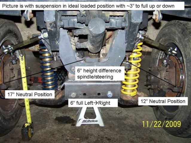
In Locost world, some people use heim joints for the ends of the steering rack at the upright. I'm using heim joints for the back suspension. You can either ream the upright out to the next bigger bolt size for the heim joint or you can make a tapered piece to fit inside the taper of the upright and use a bolt to fit through that. Just be sure you have enough travel in your heim joint. You may need high-misalignment pieces. Locost suspension is typically only 3" of travel.
How many degrees angularity at the full droop and full bump positions? Most heims with high misalignment spacers won't go more than about 22.5 degrees. BTW, keep the tie rods in the same horizontal plane as the control arms to minimize bump steer.
In reply to Jensenman:
Should I attempt to utilize a setup similar to the below picture? I'm not sure if my spindles will allow me to tie them together like that. I do like how the angle is minimized by tieing the opposite side to the steering arm.
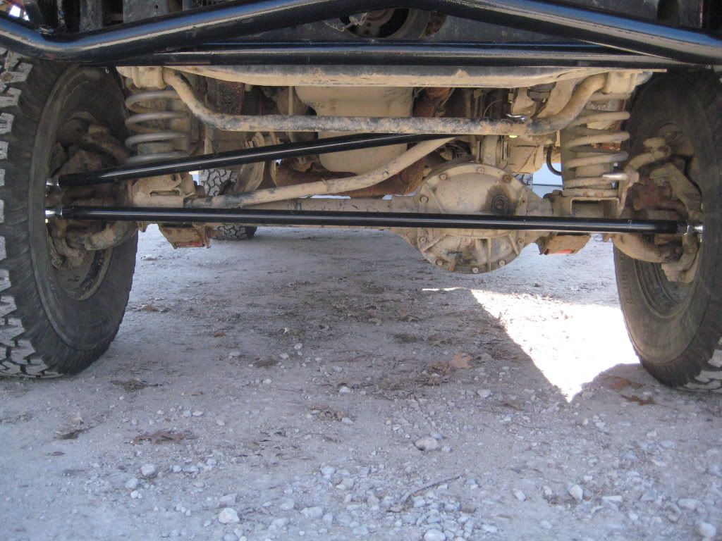
It looks like I can utilize the above setup. I have 33" from the ID of each of the spindle mounts so I should be able to get some Heims to fit. I'll have to drill the taper out so that should be fun. 5/8 is the Heim size. Looks like I will have to go larger on the upper Heim so that I can use a high misalignment spacer 3/4 with spacer to 5/8 so I can run a bolt connecting the two, or do they make Heim that does that without a spacer.
Now when conecting to the steering, the Heim/misalignment spacer on the wheel will have the bolt thru the Heim and the spindle into a tube. This tube will have another Heim that is perpendicuar to the first since the steering linkage is setup with a hole perpendicular to the spindle....Any issues with that, I see that as a benefit as that means only 1 angle to worry about (spindle)
Thoughts?
I think I'd avoid that setup due to bump steer. The straight axle setup has fixed points for the tie rod connections meaning the distance between them doesn't change. The control arms will describe an arc as they move, meaning the total distance between the steering linkage outer mounts will change as the suspension moves, this means the toe will change a bunch as the suspension compresses and rebounds. If your angularity is more than the 22.5 degrees I mentioned, I'd run down some tie rod ends which allow much more angularity and use the existing mount points. If you can find some common car (Chevy, Ford etc) out there with the thread size you need, Rock Auto can generally sell them as cheap as Heim joints.
FWIW: the common ball joint/tie rod taper is 7 degrees whether metric or SAE. TR6 Triumph and Jensen Healey upper ball joints fit Miata knuckles, for instance. Makes it real easy to swap stuff around.
In reply to Jensenman:
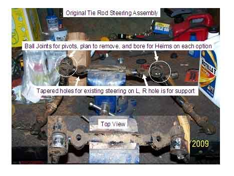
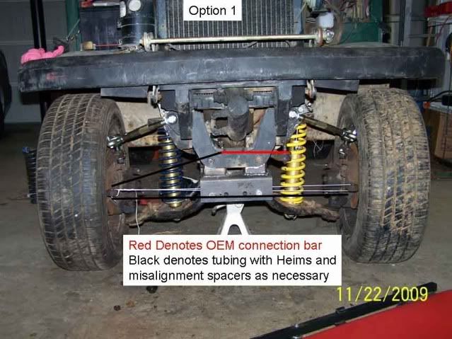
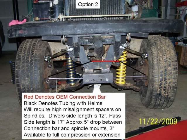
OK, I have two options to choose from, I tried to draw them out in in the below pictures. The first picture is the OEM steering setup. The center two holes are tapered and the hole on the right goes over the hydraulic steering pivot point, and the left hole is there for stabilization. In its current form I can't use anything but the center section as the ball joint pivots now hit the frame. I plan to remove the ball joint pivots and use a 5/8" heim in either of the options below. Option 2 concerns me with the angles on the driver's side. Thoughts/comments?

44Dwarf
HalfDork
11/23/09 6:38 a.m.
Well i don't see anyway you can minimize bump steer....
The steering mechinizum is just to short and hidden behind the farme.
In an ideal set up you would do this.
1) Measure from inner lower ball joint to ground.
2) Measure from outer lower ball joint (pivot point not the stud) to ground.
3) Insert outer tie rod.
4) Measure pivot point of tie rod to ground.
5) Subtract #4 from #2.
6) Shim, space, weld etc inner tie rod above #1 by the distance in #5.
Also needed is.
7) Take a stright edge run it from both inner pivots of both upper and lower control arms this is where you want the inner tie rod to be located left to right when everything is pointed straight a head.
8) Accreman? You want the inner wheel in a turn to turn a few degrees more to help pull in to the turn.
As i see this is a front steer build this means you need the rack set behind the outer tie rod ends. Because of the narrow width you don't need alot 1/2 to 3/4 of an inch.
9) run a string like in the pic get wheel pointed dead straight ahead.
10) measure from string toward the rearsay 5/8 of an inch along the angle in #7 try to get the inner tie rod located the 5/8 back, along the angled line in #7 and at the height found in #6
Yes it's a pain in the a$$ takes a long tome to fin tune it all..
There are some short aftermarket R&P's out there. Stiletto make a few.
http://www.speedwaymotors.com/Small-Rack-and-Pinion-Standard-Steering-Box,1110.html
Honestly, after looking at your pictures above I'm pretty confident that would be completely undriveable with the first option at anything above 5mph. 
The 2nd option is better(the left side as viewed looks almost spot-on), but with the two sides being unequal you're still going to have weird and unpredictable things happen when you hit a bump with the left wheel vs. the right.
Really, I'd suggest removing the springs/shocks and using some wire/rope/etc. to tie the steering with the same geometry shown in your links. Measure your static-toe, then move the suspension throughout its travel while measuring the toe. I wouldn't be surprised if you had ~1" change in toe with the first setup!
In reply to petegossett:
Based on the above comments, I think I'll be going with option 2 but at least its cheap to learn. I plan on using these in my spindles so I won't have to drill them out. It will also cut down on the angle that the Heim will have to be at.
http://www.speedwaymotors.com/Adjustable-Tie-Rod-Adapter-Stud-to-Heim,3333.html?sc=WGB&utm_source=GoogleBase&utm_medium=feed&utm_campaign=GoogleBase
Well, I have it lined up for the most part. I plan to drop the steering by about 4 inches to make the angles less on the Heims. As I put a jack under any side I don't get a noticeable change in the direction of the wheel. Also had to upgrade to 940 lb/in springs to keep the frontend up
Now I have to find out why she won't start.
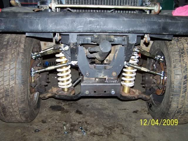
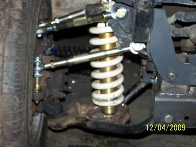
Just hang on to the steering wheel when you turn. Several people i asked about rev KPI said it will hook the turn and steer harder in to the turn instead of self neutral steering.
44

What 44 said. Reverse king pin inclination (the upper ball joint is further outward than the lower) will cause the steering to literally get yanked out of your hands as the tire pivots. If you have little or no positive caster that can make it worse. It seems to me you can fix that by putting the outer upper Heim joint below the upper knuckle mount point instead of below it. That would mean lowering the upper inner mount points on the frame, though.
If you do that, if at all possible you need to keep the steering tie rods between the control arms as viewed from the front. It looks as if you already have the tie rods in the same plane (viewed from the front) as the control arms and you need to keep it like that to minimize bump steer. Good drawing which shows how to minimize bump steer:
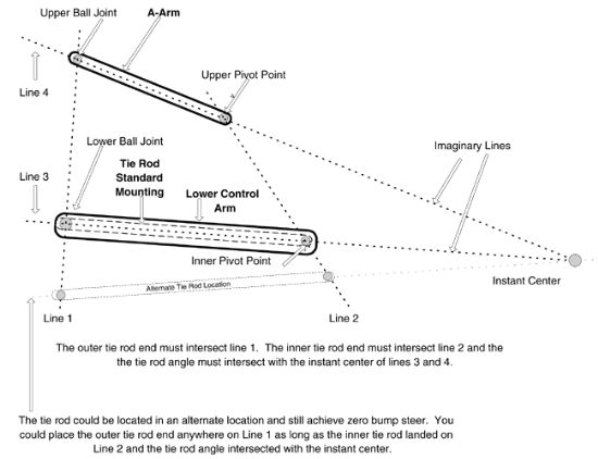
Notice how much longer the tie rod has to be as you lower it, and conversely how much shorter it would need to be as you go up and of course there's a practical limit to that. Note: It shows the tie rod at a different angle compared to the control arms, from personal experience that's a very limited amount of angle and the shorter the control arm/tie rod the less that angle becomes. it's best just to keep them in the same plane and minimize your headaches. About bump steer: at low speeds and over rough terrain you probably wouldn't notice any real handling weirdness. Higher speeds and flat land where the tires can get better grip, yeah you would feel all kinds of strangeness and unpredictability.
As far as the Reverse KPI, I suppose I will be lucky since it is hydraulicsteering vs a rack/pinion. I'm assuming since a hydraulic cylinder is actually controlling it it shouldn't want to pull the wheel?
I do plan on lowering the inner Tie Rod position about 4 inches. Biggest thing right now is getting her moving and working out the bugs.
Can't figure out why she won't start right now, I drove it in place, and now its just not happy, will crank but no fire. Changed plugs, have compression, and spark. The carb is a bit funky as its fly by wire with maual choke so I can't fully figure it out yet. Going to heat the garage up and see if its temp related.
Even hydraulic steering will get a kick back. That's why on the older recirculating ball power steering boxes or the hydraulic cylinder types ("Orbitrol', very common on construction equipment) if you jack up the vehicle and force the wheels side to side it will push fluid out of the top of the p/s reservoir, in that situation the gearbox and/or cylinder works as a pump.


