codrus wrote:
I have fresh plug wires sitting in a box, ready to go in, need to get some plugs to go with them.
I bought the proper amplified pressure sensor, need to get back to that project. Now that the holidays are over, hopefully I'll have some more spare time. :)
I'm not daily driving it (I have an Audi for that), but it does get driven to work occasionally. Smog checks in California limit what I can do with the turbo system without jumping through a lot of hoops, so for right now I'm sticking with the stock computer. Downpipe is really the only other exhaust mod I'm pondering, and that only for heat reduction.
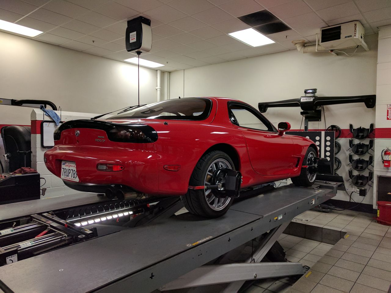
I *did* get something done on it recently though, took it in for a proper alignment. It's now running a degree and a half of negative camber up front, a degree in the rear, 6 degrees of caster, and a smidgin of toe-in at both ends. Basically treating it like a large Miata. It's much happier now than it was before.
Careful with the downpipe! There was a magazine article (I think from Sport Compact Car) that was talking about how sensitive these engines are to exhaust back pressure and related boost.
I forget the exact quote, but it is something along the lines of "When reducing exhaust back pressure on an RX7, the engine is likely to say a few words and depart the building" This was in reference to requiring more fuel when upgrading the exhaust (due to increased boost).
This is a VERY common issue on all turbo RX7s. I had the same issue on my 2nd gen when I went to a big downpipe.
Nice car! As a rotard, I'm glad it went to you, instead of someone with plans to ruin it.
You definitely need to proceed with that compression test to get an idea of the health of the engine.
Your hot start and idle issues could be caused by weak ignition coils. RX-7 coils are stronger than RX-8 coils, but they are still considered to be wearable items that need relatively frequent replacement. It makes sense, when you think about the duty cycle of the ignition system compared to a piston engine. A rotary ignition has to fire over 3 times as often, when you consider that each plug is fired every rotation and the average RPM is much higher. That higher load also breaks down the wires faster.
wvumtnbkr wrote:
Careful with the downpipe! There was a magazine article (I think from Sport Compact Car) that was talking about how sensitive these engines are to exhaust back pressure and related boost.
I forget the exact quote, but it is something along the lines of "When reducing exhaust back pressure on an RX7, the engine is likely to say a few words and depart the building" This was in reference to requiring more fuel when upgrading the exhaust (due to increased boost).
This is a VERY common issue on all turbo RX7s. I had the same issue on my 2nd gen when I went to a big downpipe.
Improving the flow sometimes results in boost creep and spike. Sometimes, the OE boost control can handle it. Sometimes it cannot - especially as air flow mods are added. A simple electronic boost control can usually cure the issue.
That said, the FD's stock pre-cat needs to go for the sake of longevity.
In reply to codrus:
You may want to consider acquiring a set of OEM coolant hoses and replace the stock ones as time allows. Ray Crowe is having a sale on them right now:
http://www.rx7club.com/group-buy-center-69/ray-crowes-rotary-winter-wonderland-megasale-1108097/
Another excellent parts vendor is rx7.com

amg_rx7 wrote:
wvumtnbkr wrote:
Careful with the downpipe! There was a magazine article (I think from Sport Compact Car) that was talking about how sensitive these engines are to exhaust back pressure and related boost.
I forget the exact quote, but it is something along the lines of "When reducing exhaust back pressure on an RX7, the engine is likely to say a few words and depart the building" This was in reference to requiring more fuel when upgrading the exhaust (due to increased boost).
This is a VERY common issue on all turbo RX7s. I had the same issue on my 2nd gen when I went to a big downpipe.
Improving the flow sometimes results in boost creep and spike. Sometimes, the OE boost control can handle it. Sometimes it cannot - especially as air flow mods are added. A simple electronic boost control can usually cure the issue.
That said, the FD's stock pre-cat needs to go for the sake of longevity.
I am under the impression that a boost controller can up the boost but can not keep it at a lesser level than what the wastegate can handle.
The increased flow will overwhelm the wastegate and boost will creep. An aftermarket wastegate, or porting the wastegate is necessary to keep the boost down with increased flow through the engine.
I could totally be misunderstanding the 3rd gen system, but that's how it works on 2nd gens.

wvumtnbkr wrote:
I am under the impression that a boost controller can up the boost but can not keep it at a lesser level than what the wastegate can handle.
The increased flow will overwhelm the wastegate and boost will creep. An aftermarket wastegate, or porting the wastegate is necessary to keep the boost down with increased flow through the engine.
There are multiple factors here. One is that a boost controller cannot lower boost pressure below the spring pressure that's holding the wastegate closed, because it needs that pressure in order overcome the spring and open the gate. The second is that a wastegate works by providing a less-restrictive path for the exhaust gasses to flow through, so that they will bypass the turbine. If you lower the restriction on the turbine to the point that the wastegate path is now more restrictive than the turbine, then you will make more boost at higher RPMs. This is generally the cause of "boost creep".
The FD has a very complicated plumbing setup for the stock twin turbos in order to enable sequential operation. There are 3 or 4 flappers in the exhaust path, plus a few more in the intake path so that it can use all of the exhaust gas to spool up one turbo at low RPMs and then switch it over to running both turbos at higher RPM. How this impacts boost creep I don't know. :)
The third factor is the question of open vs closed loop boost control. An open loop controller has a lookup table where you put in RPM (and possibly one or two other engine parameters), and it spits out a value indicating the duty cycle on the boost control solenoid to make the desired boost. The key here is that the actual, measured manifold pressure is not a part of this algorithm -- it has the factory back pressure baked into the table values. If that back pressure is reduced then the values coming out of the table are too high, and will make more boost than intended. A closed loop controller, OTOH, monitors the actual pressure, computes an error value, and uses that error to modify the value that it gets out of the table in order to compensate for changes in back pressure.
The stock controller in the FD is open loop, meaning that any back pressure reduction will have the side effect of making more boost. This is an electronics problem not a pneumatic one, and can be fixed by upgrading to a smarter boost controller. That said, the fueling algorithm on the FD is speed/density meaning that the VE curve of the engine is baked into that table as well. Removing exhaust back pressure improves VE (that's the point), so it'll need more fuel even at the same manifold boost pressure. So even with a closed loop boost controller keeping stock boost levels, it's possible to run the engine lean if you reduce the back pressure too much.
What the guys at Mazdatrix told me is that there are three major restrictions in the FD's plumbing -- the main cat, the downpipe/pre-cat, and the intercooler. Supposedly you can get away with upgrading one of those without needing get into major fueling changes, doing two is iffy, and once you do all three you're well into the area that you need a full ECU on the car.
I'm not interested in putting a standalone ECU in the car, so I'm considering very carefully what I do to it.

2GRX7
New Reader
1/7/17 5:36 p.m.
You may want to reconsider a stand-alone simply because you'll get an adjustable computer with WAY MORE computing power that can handle all of your needs (including boost control).
Currently, I own an unmolested FD (engine-wise, aftermarket downpipe/intercooler, no pre-cat). When I moved from Michigan to L.A., my car drove like E36M3 . When the primary turbo came on boost, there was an annoying (scary even) drop in power. I couldn't figure out what it was. I have a friend that's a rotary tuning GOD who explained that the octane differences in gas could make a huge difference.
I ended up purchasing an Apexi Power FC. Not not only was there a noticeable difference in smoothness, engine-wise, my boost spikes were under control-no need to purchase boost control unit as that would have been 1/3 the cost of the Power FC.
Now this is not to say get the Power FC. If I were getting one today, I'd go with MegaSquirt II.It's a hell of a lot cheaper and can handle your boost control needs. You can get most companies that sell the ecu to put it together for you ($375-450 range).
In terms of tuning, the ONLY tuner to go to in the L.A. area is Eric Rhee over at Westech Tuning. He is a good friend and a rotary guy first, so you can trust his tune.
If I were putting an ECU in it, I'd do a megasquirt 3. That's what I have in the Miata, and I'm very pleased with it. I generally do my own tuning. :)

2GRX7
New Reader
1/8/17 12:08 a.m.
MegaSquirt 3-excellent! You'll be happy to have made the switch.
Went for a drive in the hills today. Saw this on the way:

I found it amusing because my FD is one of the few cars around that gets worse milage than that Lightning... :)


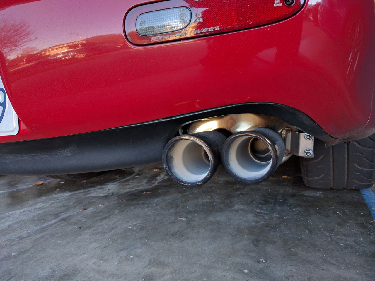
Hm. The tailpipe was full of carbon before I went on this drive. I guess the exhaust got a bit warm... :)

YoloRX7
New Reader
1/22/17 9:36 p.m.
You've caught my interest.
Hm. Got in the FD to drive it to work today, and it wouldn't start. Crank-crank-crank-stumble-stall. Did it a few times in a row, gave up and drove the Audi instead.
It ran fine on Tuesday, when I backed it out of the garage so I could get the Miata off the lift. I seem to recall that rotaries really don't like to run for 30 seconds and then shut down -- did I flood it or something? Need to go do some googling...
So yeah, went and read up on it and I definitely flooded it. Found a de-flood procedure (remove main relay, spray some WD-40 into the intake, crank with throttle open to clear) and it started up fine, if a little smoky. Yay! :)
Drove it to a local import car meet this evening and parked next to an RX-4 sedan, an older Toyota (Corolla? not sure, something from the 70s) with a 13b, and an FB.


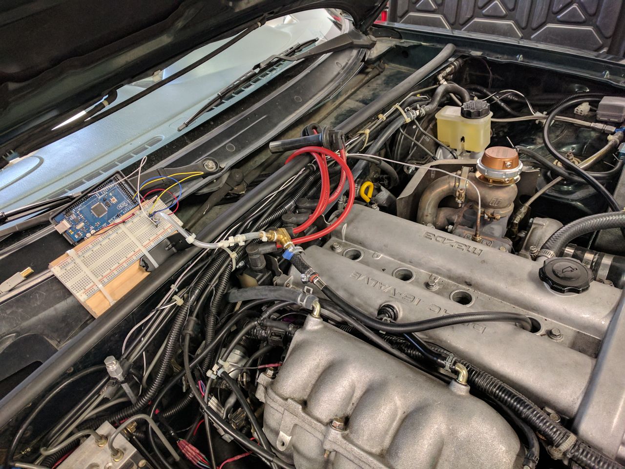
I finally got around to looking at my compression tester project again today. The new sensor is a Honeywell HSCDANN150PASA5 -- a 0-150 psi absolute pressure sensor in a 8-pin DIP package with an SPI interface. It plugs into the Arduino fairly easily:
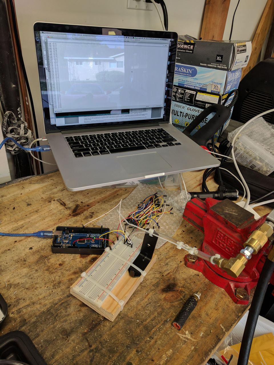
The sensor is in the middle of the breadboard, with the vinyl tubing running to it. The black bracket is just to provide some strain relief otherwise the hose will rip the chip out of the board.
After hooking it up and testing the software with my air compressor, I decided to test it on the Miata first because it's a lot easier to access the spark plugs on it. A hodgepodge of size adapters take me from vinyl tubing to brass NPT fittings to a short piece of hose, clamped onto the compression testing hose from a cheap Harbor Freight compression tester. I ran the normal compression tester gauge on the Miata first just to get a baseline -- it came it at 125 psi in all four cylinders.
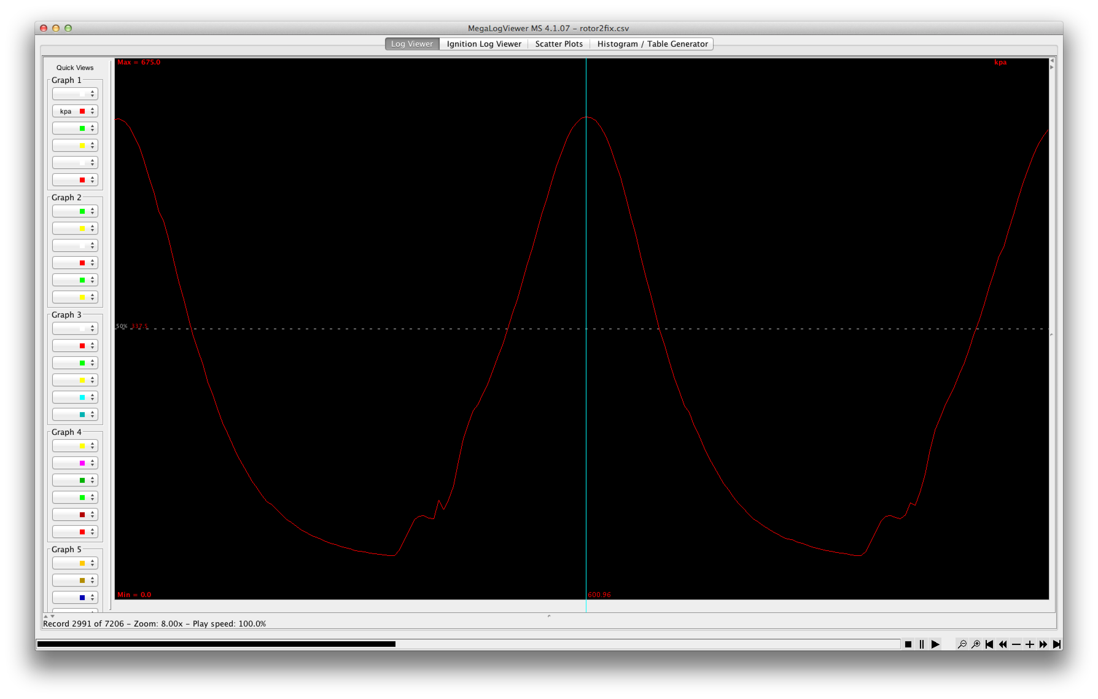
So I cranked away, the Arduino is measuring pressure and putting out CSV data at 100Hz and I'm capturing it on the laptop. Feed it into MegaLogViewer, and we get:
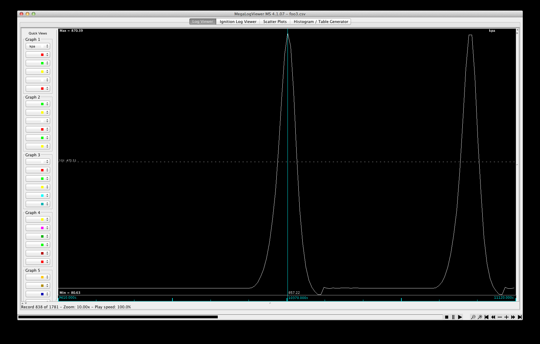
I'd say that's a success. The peaks are 600 ms apart, that's about 200 RPM. It goes from 100 kpa (ambient) to 850 kpa in each peak, which works out to 120 psi, same as the gauge.
So now to run it on the FD. I also have new plugs and wires for it which I wanted to do at the same time. So I decided to start with the wires, swap them while the motor was cold, then warm it up for the compression test. AUGH, getting the plug wires out on a FD is a serious PITA, they're buried underneath the throttle body. I managed it, although the throttle body gasket was a casualty in the process. Naturally this was half an hour after the Mazda dealer closed, and the local FLAPS hasn't even got a listing in the computer for it. So I made one out of gasket paper -- not perfect, but it'll do for now.
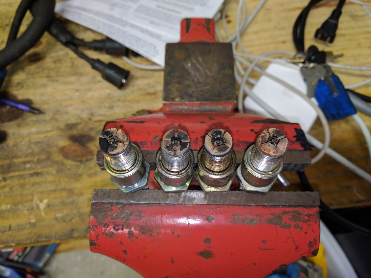
Got the plug wires in but by that point I wasn't up for actually doing the compression test, so I just put the new plugs in and called it a night. The car definitely runs better on the new plugs. Not too surprising, given that the old ones looked like this:

YoloRX7
New Reader
3/8/17 9:33 p.m.
Really odd looking spark plugs. Are the electrodes like that on all FDs?
They're like that on FDs and RX8s at least.
AIUI, rotaries require low profile plugs for apex seal clearance. Dunno what FB plugs look like?

Jroc
New Reader
3/9/17 9:21 a.m.
Beautiful car, glad its being saved and getting a little resto-mod action
In reply to codrus:
I'm pretty sure they all look like this, but it's been quite a while since I had an FB or FC.
Pretty much all rotary plugs look like that they are marine style. the rx8 I have came with a more traditional plug style which I thought was unusual but it may have been replaced before.
If you get that arduino comp tester working good I would like to buy one off you. As I have 3 wankels and 1 renesis.
In regards to the boost creep issue, its simple = the exhaust has a tuned back pressure to the boost pressure, when you remove the back pressure it creates boost pressure the ECU gets scared, cuts fuel and you detonate the engine. When doing exhaust mods you need to update the fuel system to support.
fidelity101 wrote:
If you get that arduino comp tester working good I would like to buy one off you. As I have 3 wankels and 1 renesis.
I don't plan to sell them, but I'll certainly post the plans and source code for it once it works. It's pretty simple, this sensor HSCDANN150PASA5, an Arduino (I'm using a Mega 2560, but any Arduino will do), 5 wires (power, ground, MISO, clock, chip select), and about 30 lines of C to poll the sensor every millisecond and print out the value. Add a few vacuum lines, fittings, and a hose from a compression tester (without the one-way valve) and you're done.
Actually, realistically, it's working now, I showed that on the Miata. The open question is how to calibrate it, because the numbers that most people look at to determine overall health (as opposed to comparing rotor vs rotor and combustion chamber vs combustion chamber) are normalized to a standard value and I'm not sure what all the normalization factors are. Need to do some more research on that.
Love the compression tester. Are you an EE, or do you just like playing with electronics?
Sky_Render wrote:
Love the compression tester. Are you an EE, or do you just like playing with electronics?
I'm a software engineer, I've been doing embedded systems development for a couple decades now. Stuff a lot bigger than an Arduino normally. :) The hardware is something I'm just getting into recently.

So I ran the compression tester on the FD today. Engine was hot, had been driven 10+ miles, then sat for 30 minutes while I hooked everything up and figured out how to disable the coils for the test. I ran the test just like on the Miata -- both leading plugs out, fuses/relays pulled, throttle wide open, rotor 1 first, rotor 2 second. I tweaked it to log data at 500Hz, rather than 100Hz so as to get more resolution, and wrote some python code to analyze it.
Note that I haven't normalized the data yet, so the absolute values are likely to be a bit low. In particular, there's a bunch of extra volume inside the adapter fittings & vinyl tubing to get from the end of the compression tester hose to the arduino's sensor. I think you're also supposed to normalized based off ambient temperature & voltage and stuff like that -- haven't figured that out yet.
For rotor 1 I got peaks of 640, 650, and 650 KPA (absolute) in the three chambers, or 78, 80, and 80 PSI (gauge).
For rotor 2 I got peaks of 597, 600, and 590 KPA (absolute) in the three chambers, or 72, 72.5, and 71 PSI (gauge)
Looks like both rotors have one chamber noticeably lower than the other two (side seal?) and rotor 2 is significantly lower compression than rotor 1.
Graphs. Rotor 1:
(click on image for high-res)
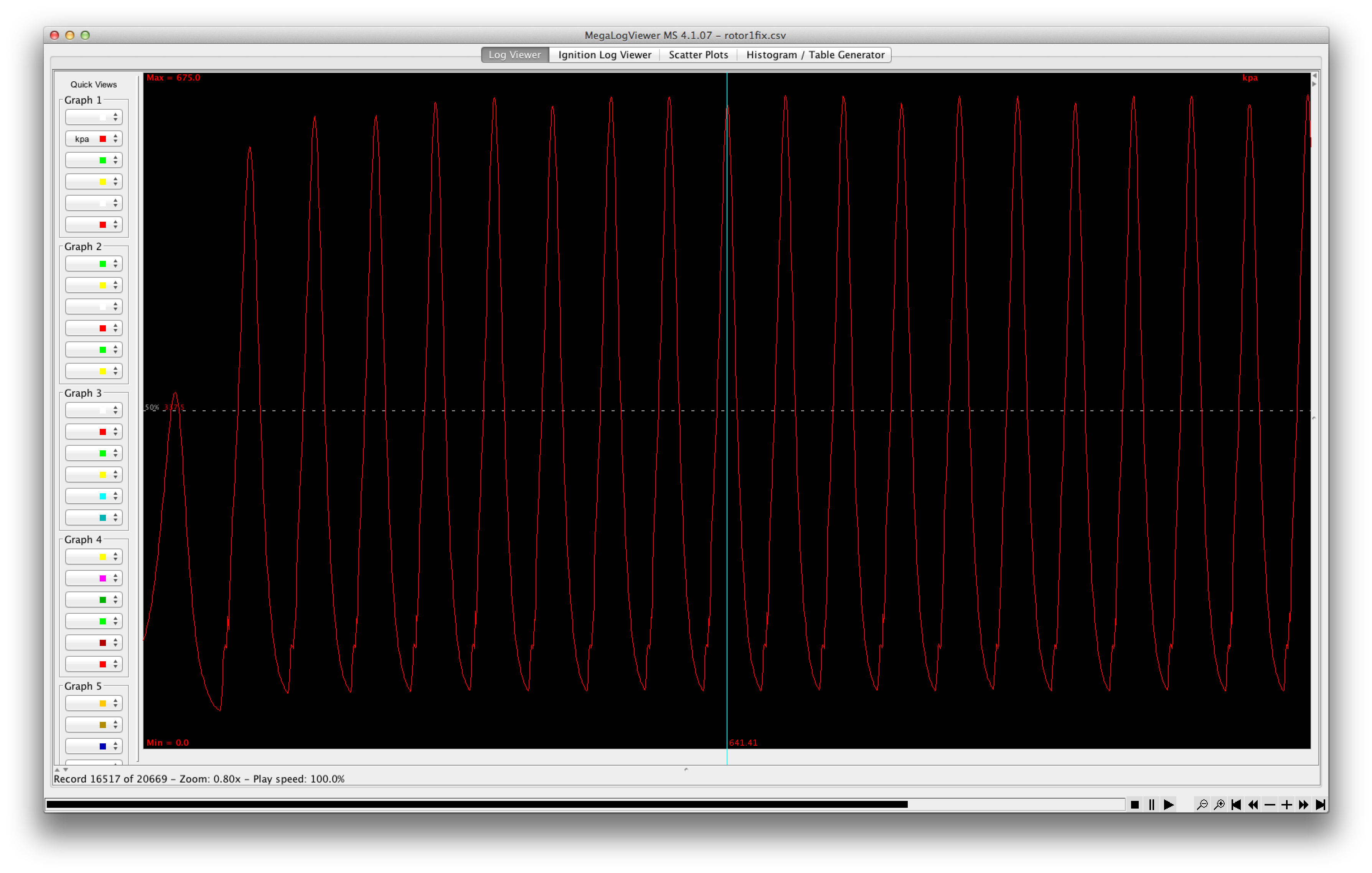
Rotor 2:
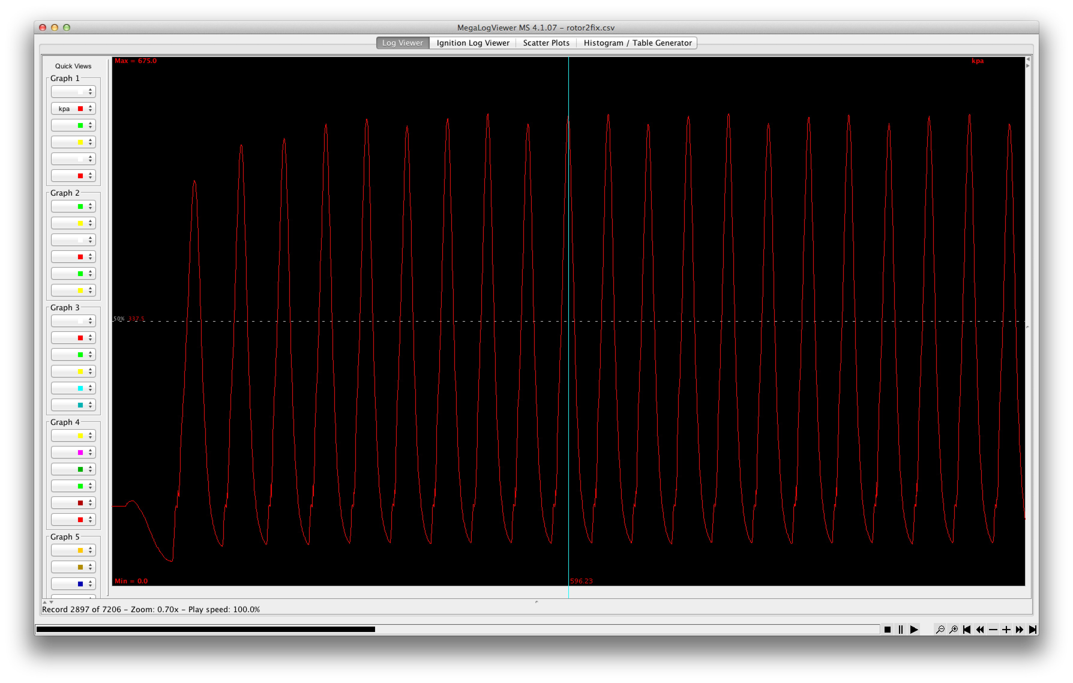
I think I'm going to take it to a local rotary shop and have them give me a reading with an existing commercial tester to see how my numbers compare.
Zooming in there are some interesting jaggies on the upward slope -- anyone know what causes this? Is it just a weirdness of the housing geometry?
