Great work! I'd call this more than just a dyno, you want to run road simulation schedules in with this thing. THAT is a LOT harder to do! Impressive that you've gotten the basic dyno part down. I'm looking forward to the rest.
Thanks for the comments!
This is the most complicated thing I have ever built in the garage. There are a few safety issues that still need to be addressed and a whole lot of software needs to be debugged, but it's almost done.
in reply to Kenny_Mc:
Interesting idea..... hmmmm, I do have a second pump in stock.
My thought being that it would take the same amount of space roughly, and you could use it on the actual car you're experimenting on, or any car for that matter. Properly designed you'd still have the flexability to run it on one pump coupled to an engine on a test stand.
Yeah, I'm a mechie, but I've been trying to pick up Python and C in my downtime.
I've got grand delusions of a flow bench that may need some arduino-driven brains.
Very interesting project you have here! Do you think the hydraulic fluid could be cooled enof on higher horsepower engines?
Thanks!
The jury is still out on the cooling capacity. When warmer weather rolls around I'll test out the heat exchanger.
I sort of overlooked a few things when I thought up this project. I'm not really certain how fast the hydraulic pump is rated to spin and a few other things. I guess my point is this dyno probably wont be able to handle more than 60HP. I'm perfectly happy with that...for now.
Anyway, I have a huge update prepared and need to shoot some video and pictures. Long story short...it all works! To be specific, the fully automatic controls work great and I'm able to run automatic test profile with my hodgepodge software arrangement.
Some safety stuff was taken care of and I have been doing some baseline engine development. A few of the neighbors said it sounds like I'm running and airplane behind the garage.![]() I may have to do something about that.
I may have to do something about that.
Stay tuned, big update coming soon!
I just fished my water brake dyno for tesing racing 4 cylinders & v 8 engines do you have a address I can send you some pics I tried ccontacting you through here but it wont let me.I would also like to talk to you about the throttle control system you made.Im probably 4-5 hrs from you I know what kinda weather your dealing with right now its frigging cold!
Hi 'ya,
I look forward to seeing your dyno pics.
For the throttle, I'm using a 127oz, .9 deg stepper motor (400 steps per revolution) The controller is set for 1/16 microstep that gives fluid like movement to the throttle.
I ended up having to remove both throttle body return springs and using a light weight return spring. The stepper motor was having trouble opening the throttle with both OE springs in place. I'm running the throttle with a 12 volt 2 amp power supply.. The power supply was free but it many not be enough power.
Anyway, I really like the .9 degree stepper motors but more powerful 1.8 degree motors are plentiful
Throttle position is dead reckoning with zero feedback. The software adds or subtracts steps according to the position of the knob (manual mode). In automatic mode it is a convoluted process based on RPM.
It's been on and off cold lately so I haven't been playing as much as I would like to, however the dyno is fully functional now. You're more than welcome to stop by and see it in action.
unevolved wrote: So are you running the throttle 1:1 to the stepper?
Yes, the stepper is directly coupled to the throttle shaft. This seemed the simplest and most safe approach to the problem. When the stepper controller is disabled, the throttle motor will go limp and a spring will snap the throttle shut.
Disabling the throttle is a nice feature, however my emergency stop protocol cuts power to everything for a full stop.
RossD wrote: You could run your own business tuning small engines.
Actually, I put together a film crew and we are going to do a bunch of youTube videos. The video project is adsorbing every free second I have.
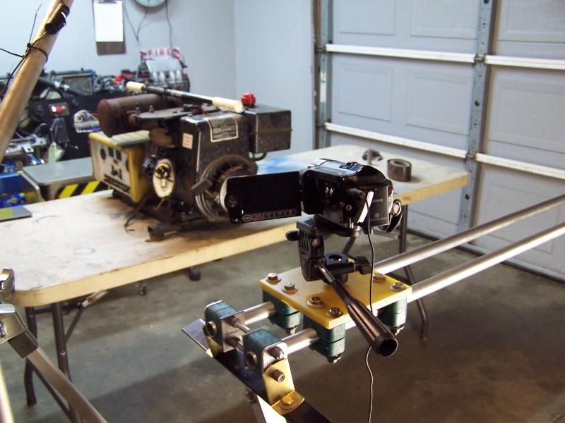
Stay tuned!
In reply to unevolved:
LOL, "Stay Tuned" is actually the name of the show.
If you look closely at the photos, the background changes at the start of page three in this build thread. I'm surprised nobody figured it out.
Jim
In this episode, Mr Fusion gets a gasoline enema, Windows get's nuked and Beavis & Butthead finally learn to talk + moar!
This project took a giant leap forward with the successful test of the fully automatic dyno controls. It's been a busy several weeks tying up loose ends and getting software/hardware sorted out. That's right this will be a massive update with pictures and videos and girls in bikinis. I'm banking on the reader to skim through the text and forget about the bikini thing because that is not going to happen.
Anyway, the incredibly difficult task of merging all the controls both manual and automatic plus several layers of safety into a single exactable program has been finished. Well, to be specific, the core program is finished. ... 'ya know, just like Microsoft Windows is "finished". I'm sure there will be some software updates and new features down the road but overall it's a turnkey system.
The current features include
Manual throttle control
Manual load control
4 manual hard wired Emergency stop buttons
Two wireless Emergency stop transmitters
Passive manual and automatic control lockout.
Fully automatic throttle and load control
automated engine warm up
automated dyno warm up
automated speed and load for Megasquirt volumetric efficiency calibration
automated 15 min expressway test.
Automatic system shutdown (Electronic E-STOP)
There are a few more features in the works however nothing ground breaking. I'm also limited to the single "real world" expressway test for now. This sort of test was built with real data from the B3 Miata. Unfortunately the Miata is off the road for the rest of the winter and I lack the data to assemble different real world tests. I'll put together a few more tests based on assumption and that should be good enough for now.
Windows and Megasquirt....
To begin with, I decided to upgrade the firmware on the Megasquirt II. In the end, it was a good move, but it wasn't as easy as I thought. The laptop had been a bit dodgy and I didn't trust it to run long enough to upload the firmware. I'm a man of very little patience when it comes to computers and when the laptop started to get flakey I didn't hesitate and took the nuclear option. A good nuking always starts with a DoD wipe followed by a full rebuild of the operating system. Yeah, it's a bit nerdy but I like my computers fast. I'm extremely pleased with the outcome, especially since this is a very durable XP system.
A fresh copy of TunerStudio and MegalogViewer were installed and nothing else. This time around, the laptop is strictly for the Megasquirt support. The newer version of TunerStudio is slightly different, so I decided not to import any of the older MSQ data and did a start fresh. The whole purpose of the dyno is to tune, so guess it starts now.
Mr Fusion...
The device formally known as Mr Fusion has been re-purposed and is now an injector profile tool. According to the internet the tiny injectors used on the Festiva engine allegedly flow at 110cc min or 11 lbs./hr. Even though the internet is a totally reliable, a second opinion wouldn't hurt.
To build a profile, I started with a $30.00 remanufactured injector. Remanufactured parts have a shadowy history. All you can ever know is sometime in the past, some major E36 M3 happened and a part of somebody's car ends up on ebay. Who the berkeley knows the whole story, but this injector looked brand new. Good enough for me.
The new injector was installed in the device formally known as Mr. Fusion and was pressurized to 50 PSI. I was able to determine the actual flow rate and null time. Things are finally starting to go as planed.
All right, Beavis and Butthead...
Because I have a sense of humor, the two Arduino Mega 2560 micro's were id tagged Beavis and Butthead. As you can guess, both micros were a bit slow communicating. The desktop computer would issue a request for data via the RS485 multi-drop and a few seconds later one of the Arduinos would respond ... "uhh.. oh yeah"... and spit out the data. Whelp, it doesn't take long for this to get annoying. In the end, I couldn't find any faults with the RS485 network but I decided to go with two separate serial ports. Now each micro has its own communication pipeline. While Beavis and Butthead are still 8-bit idiots in a 64-bit world, they are finally up to speed ... bla bla bla. I'm truly sorry for all the boring computer nerd stuff. This is the last post on the technical support crap..
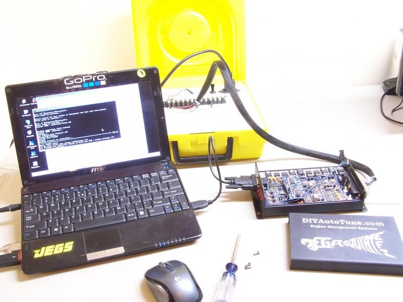 The laptop was acting a bit dodgy so I nuked the operating system. After the smoke cleared, MegaSquirt firmware got updated....
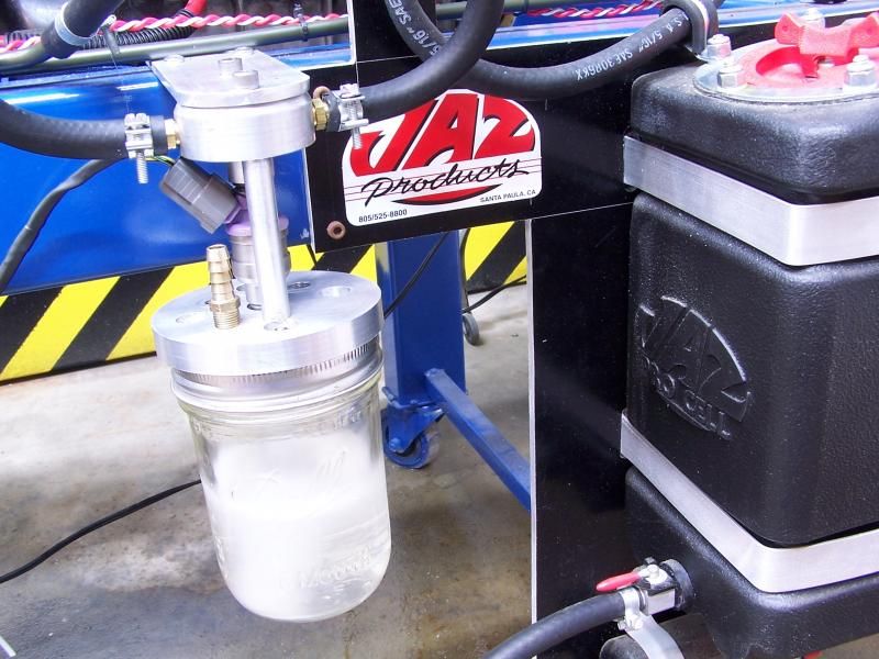 The device formally known as Mr. Fusion gets re-purposed. After a 50 PSI gasoline enema, and we learn the truth. Looks like the injector flows 134 CC per min. @ 50 PSI. It doesn't take a rocket appliance to figure out the internet was wrong.
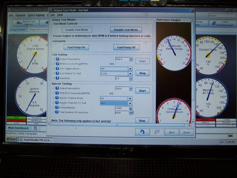 TunerStudio has a cool test feature for figuring out injector lag or dead time.
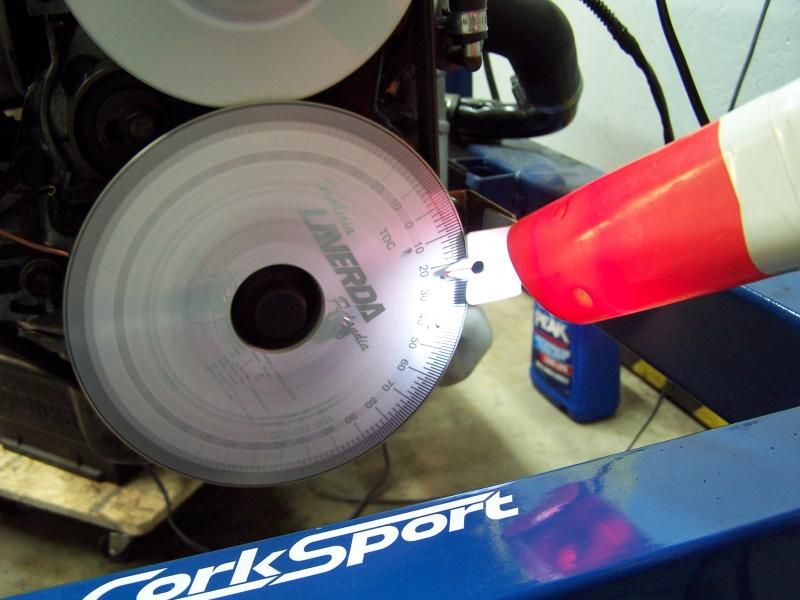 Finially built a pointer for the degree wheel
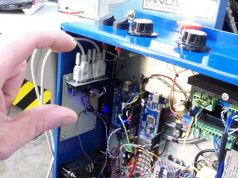
Beavis and Butthead were having communication problems........A set of serial to TTL converters get 'em to talk in real time.
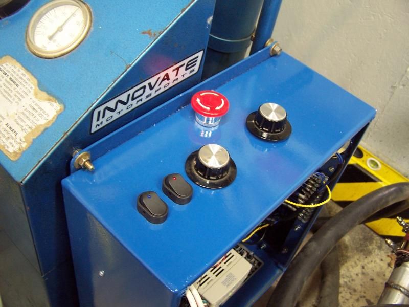 Flipping the switch on the left commands the PC to deactivate the controller. This is a passive and polite way to take the system down. Taking the controller off line allows the user to load a test profile into the PC while the engine is still running. No worries, just a little safety precaution. Once a test profile is selected, the switch is bumped and the controller comes back to life. At this point the PC is locked and loaded , however it can only monitor sensors and has no authority.
The switch on the right transfers full authority over to the PC. After a ten second delay, the PC can fiddle the throttle and apply the load as required. The PC also has the ability to punch an electronic E-STOP if it detects a fault. There are also four other hard wired E-STOPS. One of the hard wired E-STOPS is conveniently placed by the exit door. I also have two wireless E-STOPS just in case. A total of six emergency stops....cuz 'ya never know.
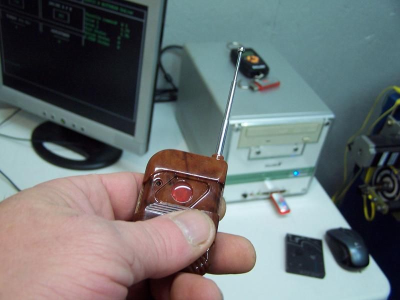 Wireless emergency stop
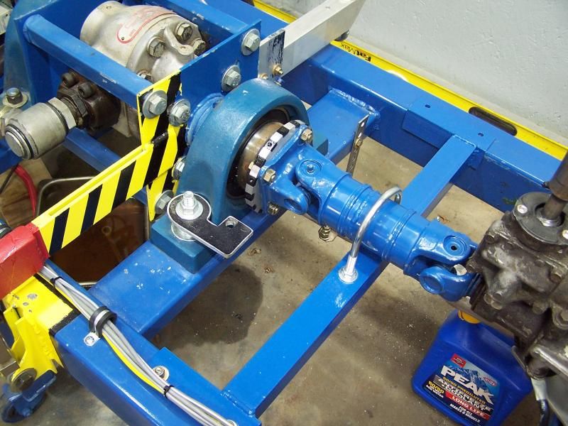 A simple driveshaft loop was fabricated. I still don't want to stand near this thing when its running a test.
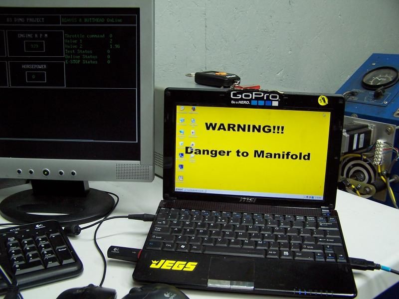 if you have to ask....
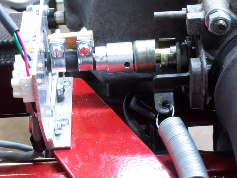 An aluminum coupler was fabricated to eliminate any slop in the throttle servo.
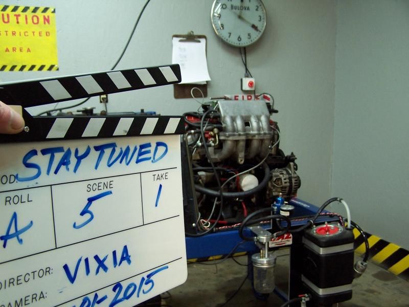 Here is something that I hadn't planed on when I started this project. A few months ago a friend suggested that I do a few YouTube videos on some of the experiments. The video project added yet another layer of complexity. Lights, cameras, audio and editing software plus zillion little details. Producing an interesting video ain't easy. Anyway, I have been keeping the video project top secret but the cats out of the bag. The good news is, the first video is done and is uploaded to YouTube. The bad news is its too cold to finish the other videos so it may take another week or so before moar videos are uploaded.
Video
Ok, now it's movie time. Go ahead and grab a beverage, find a place to sit and settle down. When your ready click here......The dyno.....

Hey, that was pretty cool. Doing video must be hard, but I think you definitely pulled it off for a first episode.
All the engine dynos I've seen have used an airplane-style throttle controller but the rotary dial makes a lot more sense to me, especially if the computer is doing most of the work.
Well placed first aid kit. Hopefully you never need it.
ssswitch wrote: Hey, that was pretty cool. Doing video must be hard, but I think you definitely pulled it off for a first episode. All the engine dynos I've seen have used an airplane-style throttle controller but the rotary dial makes a lot more sense to me, especially if the computer is doing most of the work. Well placed first aid kit. Hopefully you never need it.
Thanks, It's actually a lot of fun shooting and editing a video. I still have a lot to learn. I got some feedback from a buddy, he was like...Damn, how much coffee did you drink? LoL,... Well, some of the scenes were re-shot when the temperature dropped way below zero and the coffee machine was the only thing putting out any heat........
It's conceivably possible to sustain a worse injury just getting to the first aid kit. There is a lot of non medical tech gear and batteries in the kit, possibly a box of Band-Aids, but I'm not sure.
Pacing and cadence are really hard to master. I don't really have any advice for that other than being constantly mindful. At least there's no time limit on youtube videos anymore.
Are you planning on throwing your code up on github or something for people to look at and contribute to? I caught a few typos that won't be too hard to fix, but I'm primarily interested in learning what you've got going on each Arduino.
The spelling errors are probably in the Quick Basic code on the desktop. I'm terrible at proof reading the text and a lot of stuff gets past me. ![]()
The Arduino code is fairly simple and theoretically only one Micro should be required. I ran into a problem getting around a routine that involves an interrupt for measuring the RPM. Stacking all the stepper motor code around the RPM code made the micro noticeably slower. I ended up splitting the code and using two micros to speed the system up. I'm still a noob with C and Arduino C and this is only my second Arduino project. The code is fully commented but a bit sloppy. I'm not sure how github works. If your interested, I could PM the code or I could try posting it on github.
Give it a shot, it's not too hard especially with the github 'apps' they provide.
I'm a little surprised they still make machines that can run quickbasic outside of a VM. But yeah, I noticed the typos on the PC side but are curious about how the Arduino code works as well.
What about using a dedicated counter chip to measure RPM? I'm using an Arduino Uno to read a high-speed encoder (10 MHz), and I found it's really cheap and easy to use a counter IC like an LS7366R. The counter keeps up with the encoder, and the Arduino just polls it over SPI whenever it needs a new count. The one I'm using is meant for quadrature, but there's got to be one for RPM.
You'll need to log in to post.