NOHOME wrote: Why the single shear mounting of the lower a-arm inner pivots?
Agreed. At least on a miata, those take most of the load, not the upper arm.
I would think a simple boxed x shaped piece that all four bolts went through would take care of any single shear worries as well as adding a bunch of stiffness to the whole area.
Double sheering those bolts is not necessary because of the strength of the 5/8 bolts I'm using. If the piece they bolted into was just the top of the square tubing, I could see doing that but I intentionally built it so the whole square tubing takes the force and the 5/8" rod ends are actually stronger than what I need.
Single shear is a buzz word that people love to jump on as if it's the devil. YEs single shear is bad if executed poorly, but a properly designed single shear joint is fine. There are many many OEM designs with single shear joints on suspension components that last hundreds of thousands of abused miles over salt covered pot hole encrusted roads. I think it will be fine.
The sheer strength of a 5/8" grade 8 bolt is 91,000 psi, I'm pretty sure I would have to crash into something solid to exceed that number. The reason the top bolts are double sheer is that I will likely be adjusting those up and down to move my roll center around, and if I had them adjusted at one extreme or the other, it would put excessive bending forces on the bolt.
The point with single shear is to avoid placing components into bending. Particularly when those components are mission critical, and see large shock loads and significant load revarsals in service. Not saying it won't work, or will fail, but components in shear are almost always lighter and/or stronger than those in bending, and feature less deflection.
How can you adjust caster? Seems like one side (upper / lower) needs some fore / aft movement for caster adjustment.
Also, I wound have recommended a 45 miter cut on that front box tube (for strength).
Trying "not to be so negative, just offering some constructive criticism" Looks great tho.
Kendall
Kendall_Jones wrote: How can you adjust caster? Seems like one side (upper / lower) needs some fore / aft movement for caster adjustment. Also, I wound have recommended a 45 miter cut on that front box tube (for strength). Trying "not to be so negative, just offering some constructive criticism" Looks great tho. Kendall
Caster is adjusted by moving the top front control arm rod end. I figured out a way to make it easier to adjust and you will see that update when it happens. I don't know what you mean about a 45 miter cut but the frame is not finished and there's a lot of tubes missing from the front end, still.
Screen shots of the frame in CAD, top view and side, minus the suspension.
[URL=http://smg.photobucket.com/user/loosecannon/media/MGB-GT/frame-sideview_zps775fcb34.png.html]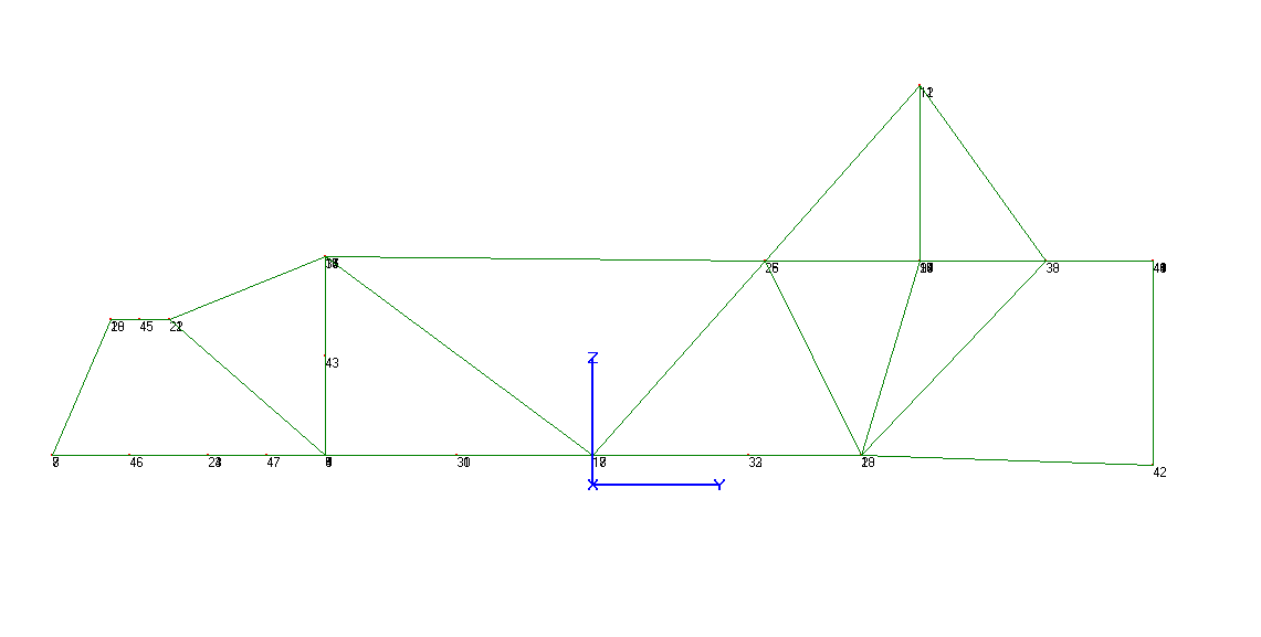 [/URL]
[URL=http://smg.photobucket.com/user/loosecannon/media/MGB-GT/frame-topview_zpsb1c4cb16.png.html]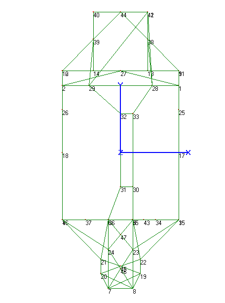 [/URL]
More reinforcements
[URL=http://smg.photobucket.com/user/loosecannon/media/MGB-GT/IMG_7377_zps9b9b38a4.jpg.html]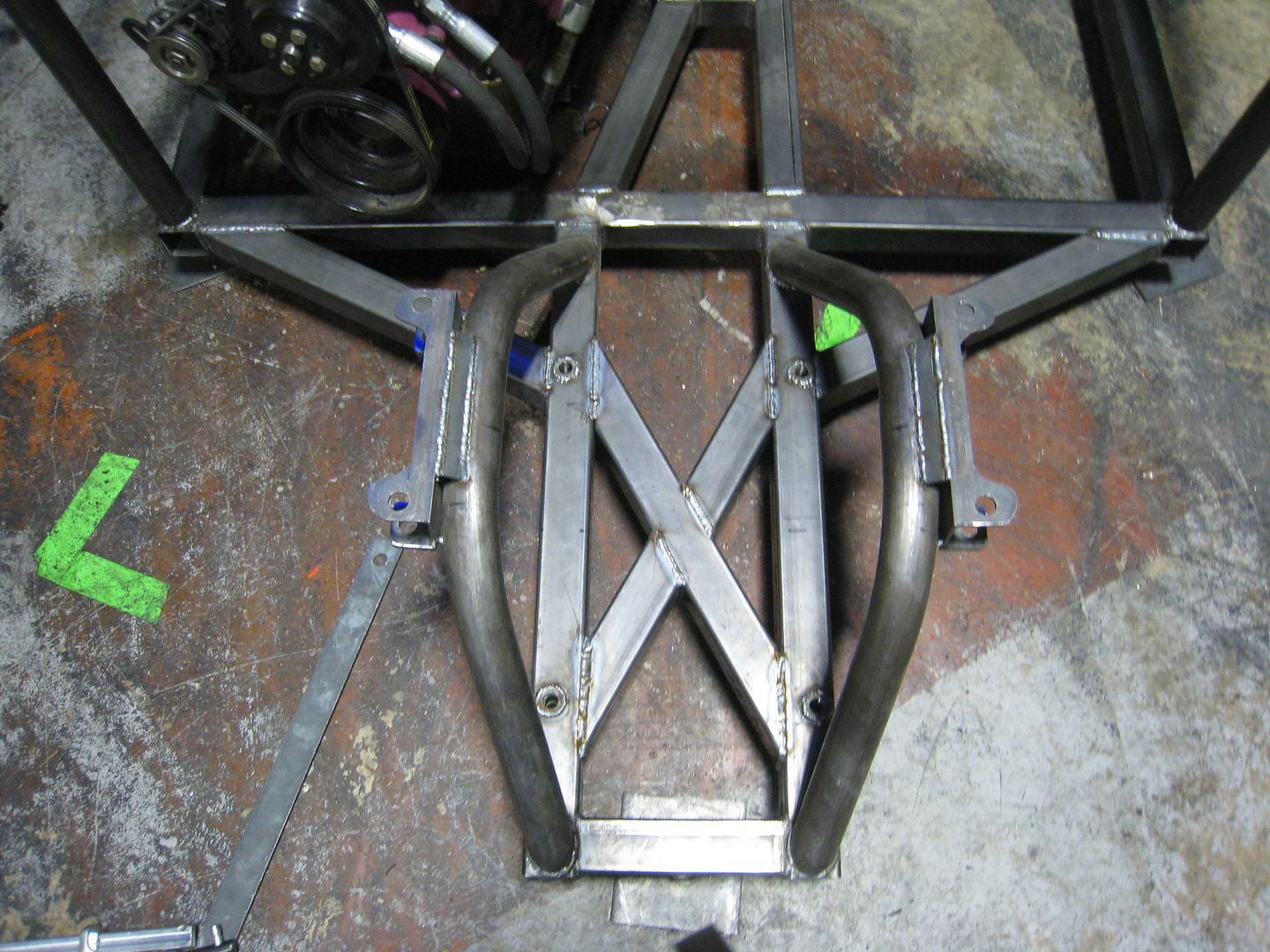 [/URL]
loosecannon wrote: More reinforcements [URL=http://smg.photobucket.com/user/loosecannon/media/MGB-GT/IMG_7377_zps9b9b38a4.jpg.html][/URL]
You know, I have been following your thread since the start of the Pink Panther project. I'm on to you.
You are not really into this for the racing like you say, you are a welding addict and just need a cover story!![]()
NOHOME wrote:loosecannon wrote: More reinforcements [URL=http://smg.photobucket.com/user/loosecannon/media/MGB-GT/IMG_7377_zps9b9b38a4.jpg.html]You know, I have been following your thread since the start of the Pink Panther project. I'm on to you. You are not really into this for the racing like you say, you are a welding addict and just need a cover story![/URL]

I love a good welders tan ;) Seriously, though, 75% of the fun is the building of something because you get a great sense of accomplishment. That last 25% is building something that does what it's supposed to do, in this case setting low lap times.
I have to deviate from the CAD in some things, like the X brace in the picture does not extend all the way to the front corners because it would involve some very complex cutting/notching of tubes to extend into the corners and would make welding almost impossible. Common guidelines for chassis stiffness is that you need 10 times the spring rate and the car will probably use springs in the 300-350 lb/in range. The chassis needs to be 3500 lbs/degree but is, according to my latest design, 7000 lbs/degree. Wow, I have learned so much building this car, then building it again
Won't you need some sort of brace between the upper control arm mounts? Something to keep the tubing from deflecting inward... oops.. I see in you cad post a listing for those at points 19, 20,21 and 22...
noddaz wrote: Won't you need some sort of brace between the upper control arm mounts? Something to keep the tubing from deflecting inward... oops.. I see in you cad post a listing for those at points 19, 20,21 and 22...
It is an X brace in CAD but I may have to change that to make room for shocks, we'll see.
These tubes are not welded in yet, it took so long to fit the complex curves that I ran out of time, but you can see where it's going.
[URL=http://smg.photobucket.com/user/loosecannon/media/MGB-GT/IMG_7386_zpsb3af4f16.jpg.html]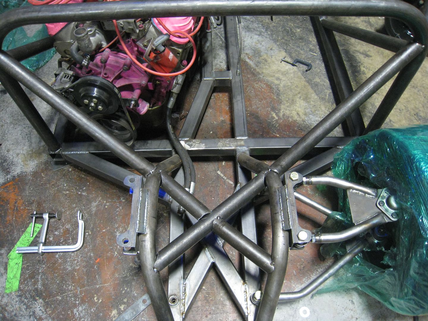 [/URL]
[URL=http://smg.photobucket.com/user/loosecannon/media/MGB-GT/IMG_7387_zps51a2537d.jpg.html]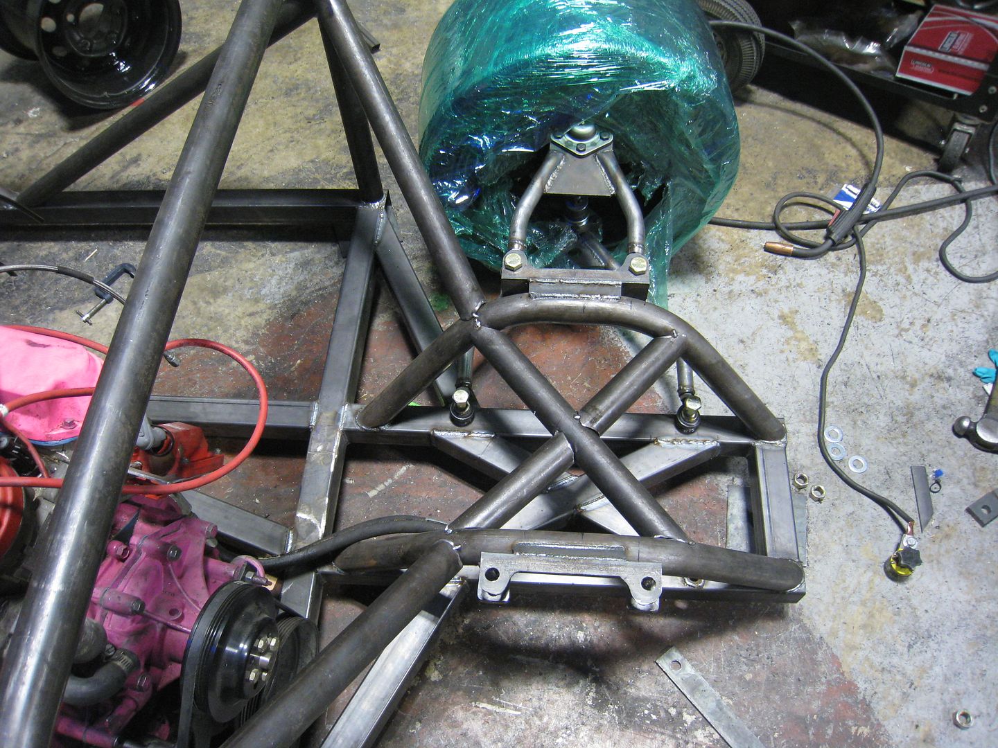 [/URL]
Today I worked on the back of the car. I welded the tube for the adjustable Panhard mount and the reinforcing tube that runs under the diff. Look closely at the tube under the diff and you will see that it uses trick machined couplers to make removal easy if I need to drop the diff. The Panhard adjusts up or down with a wrench, just like the NASCAR guys.
[URL=http://smg.photobucket.com/user/loosecannon/media/MGB-GT/IMG_7388_zps91e9feb4.jpg.html]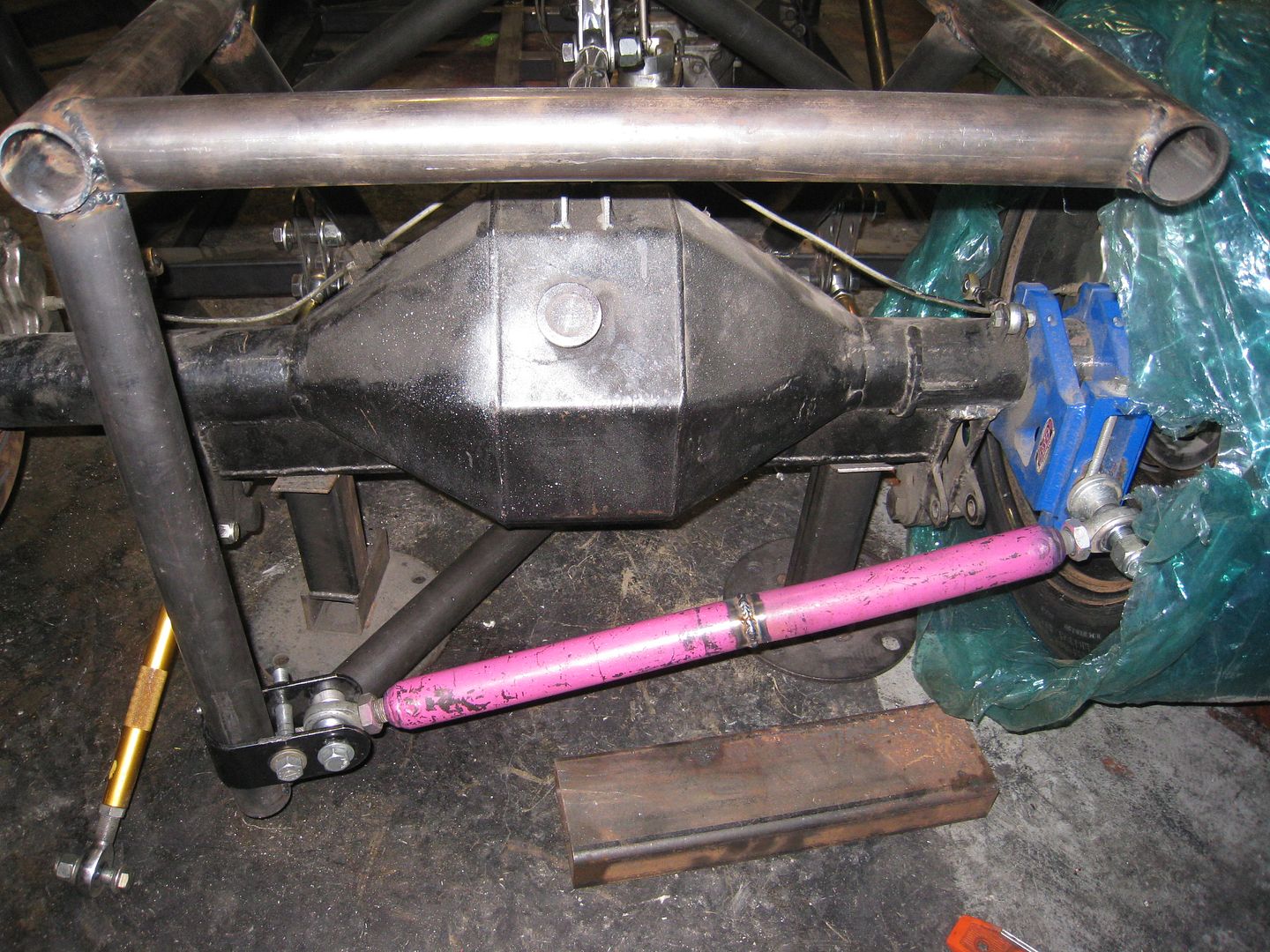 [/URL]
[URL=http://smg.photobucket.com/user/loosecannon/media/MGB-GT/IMG_7389_zps87f63d10.jpg.html]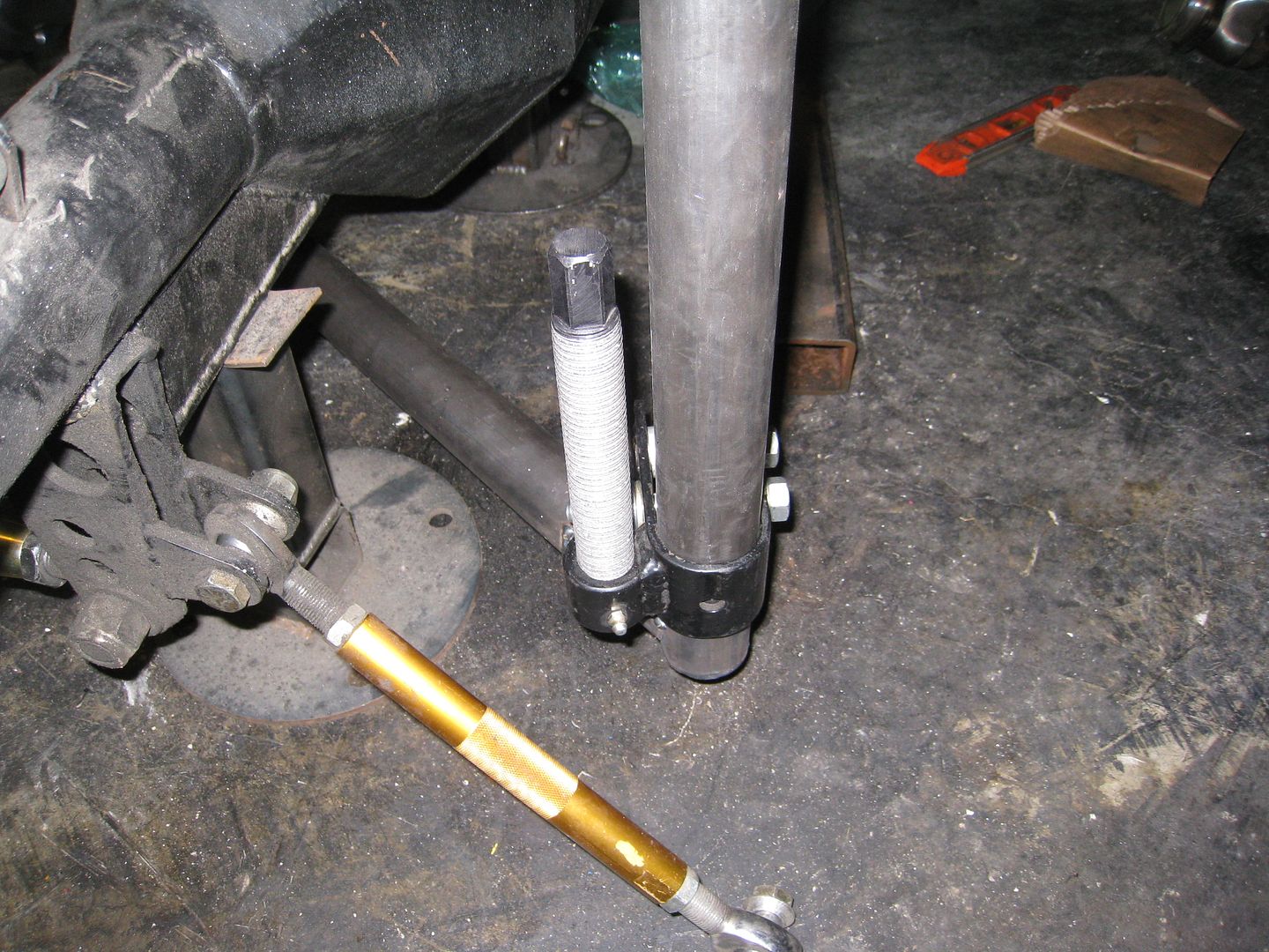 [/URL]
[URL=http://smg.photobucket.com/user/loosecannon/media/MGB-GT/IMG_7390_zpsfa742d57.jpg.html]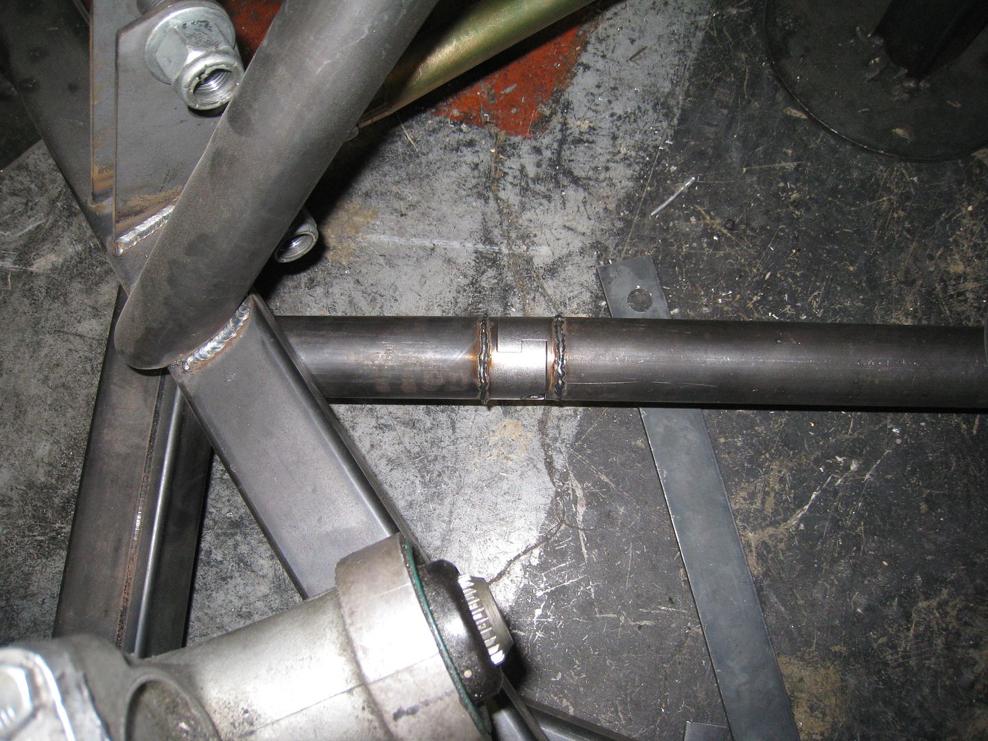 [/URL]
Staring to test fit body panels
[URL=http://smg.photobucket.com/user/loosecannon/media/MGB-GT/IMG_7406_zpsb533cb0a.jpg.html]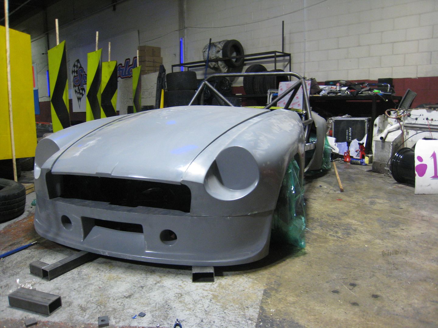 [/URL]
[URL=http://smg.photobucket.com/user/loosecannon/media/MGB-GT/IMG_7408_zps0fb5dd1f.jpg.html]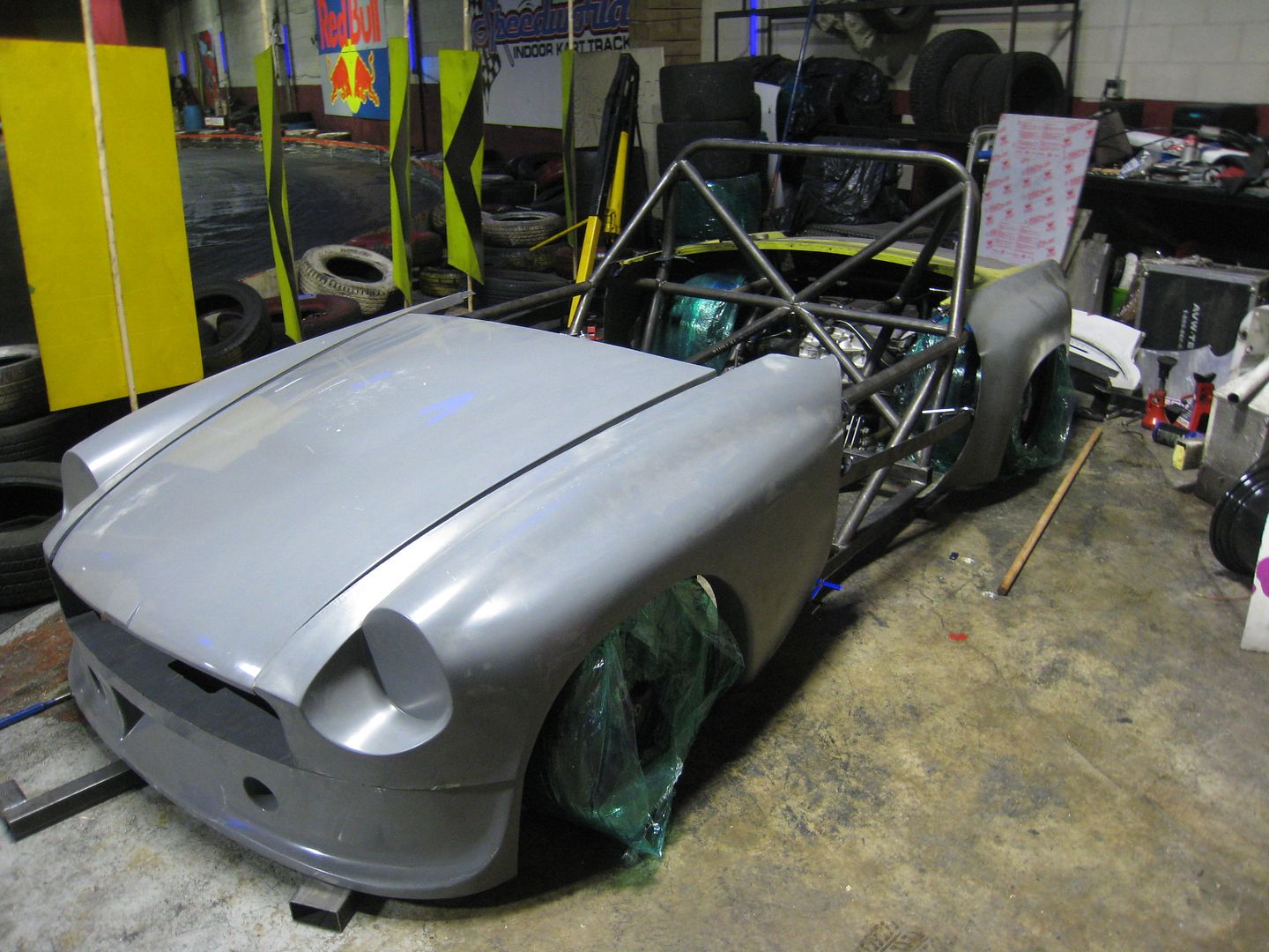 [/URL]
[URL=http://smg.photobucket.com/user/loosecannon/media/MGB-GT/IMG_7410_zps5fb243be.jpg.html]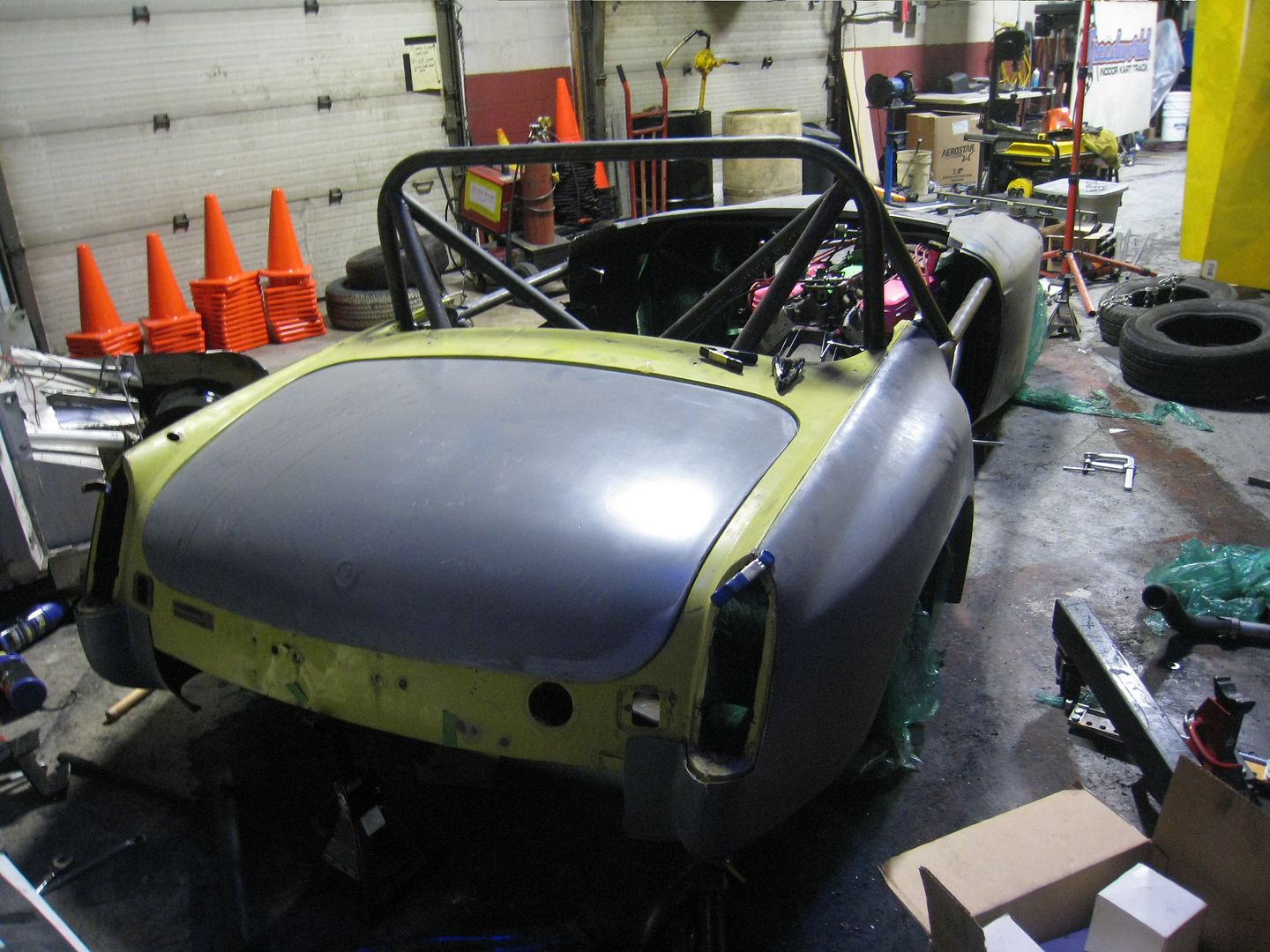 [/URL]
I'm using Dzus fasteners on the body panels because I want to be able to zip everything off quickly for access or repair. The front end should be able to come off as one piece and is height adjustable. No, the brackets are not completely welded yet.
[URL=http://smg.photobucket.com/user/loosecannon/media/MGB-GT/IMG_7413_zps9d4ccf93.jpg.html]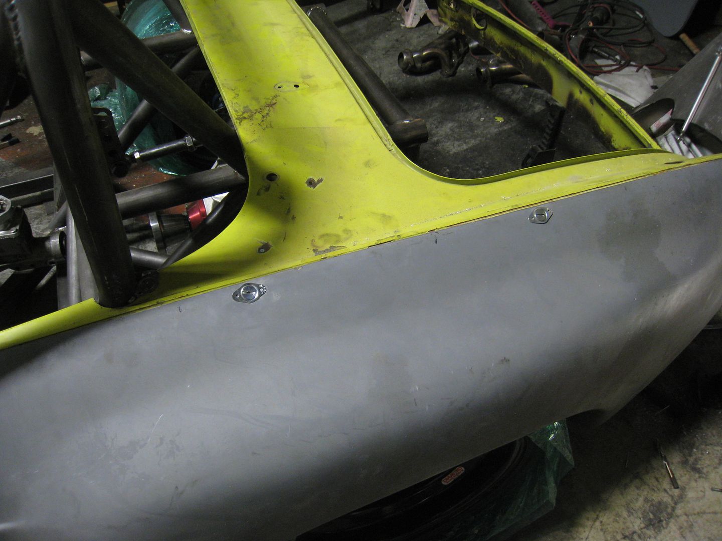 [/URL]
[URL=http://smg.photobucket.com/user/loosecannon/media/MGB-GT/IMG_7412_zpsf9a22e7e.jpg.html]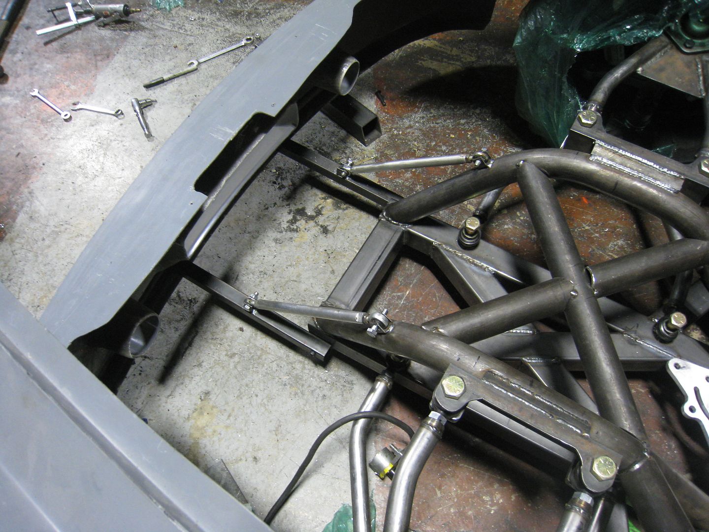 [/URL]
Mounted the radiator in the back. Does that present challenges for getting air through the rad? Most certainly, but It's offset by the extra weight over the back axle. I plan to get air from the area below the rear deck lid (immediately behind driver) and vent it between bumper/valance and diffuser. There is precedent for this, Del's EM Jeep has the rad mounted out back.
[URL=http://smg.photobucket.com/user/loosecannon/media/MGB-GT/IMG_7414_zps6a06b117.jpg.html]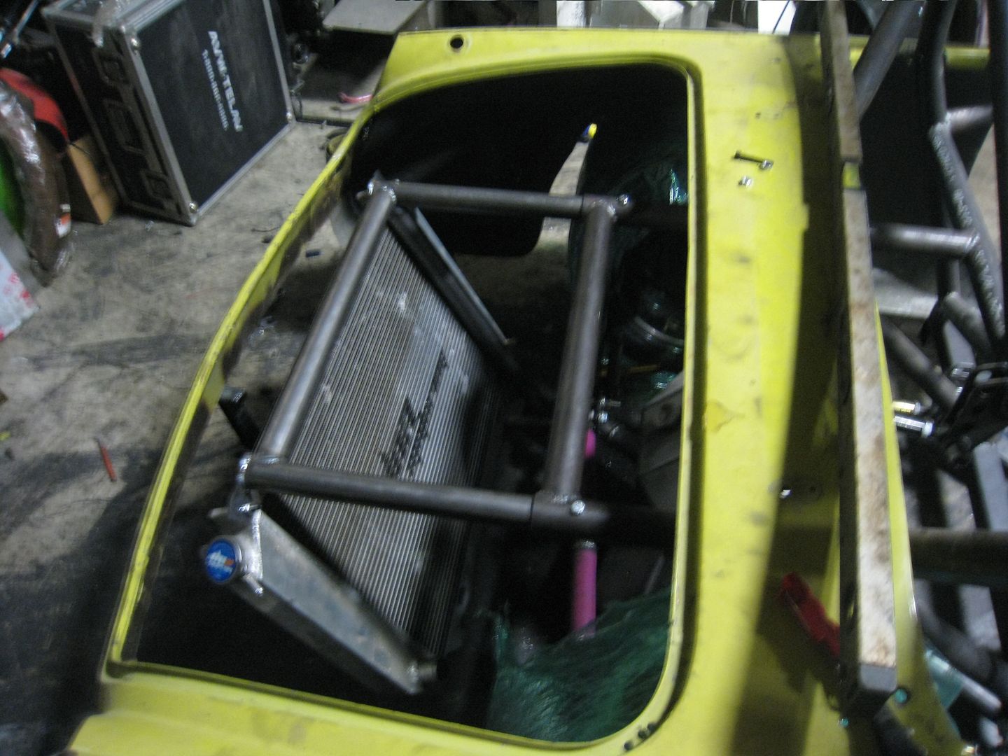 [/URL]
[URL=http://smg.photobucket.com/user/loosecannon/media/MGB-GT/IMG_7415_zpsdc07e7a6.jpg.html]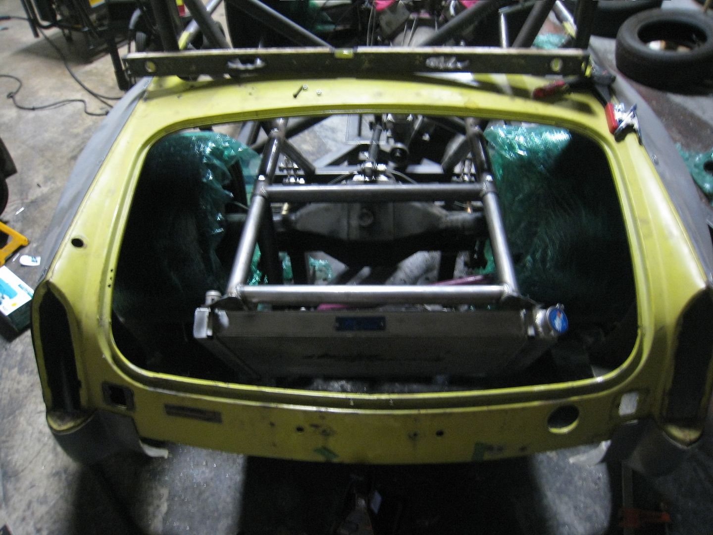 [/URL]
You should see if you can route air from the front of the rear flares to the front of the radiator. I think that would be the best way to do it in terms of aerodynamics.
GameboyRMH wrote: You should see if you can route air from the front of the rear flares to the front of the radiator. I think that would be the best way to do it in terms of aerodynamics.
That's a good idea. Know of any pre-fab ducts that could be attached and look good?
You'll need to log in to post.