A phrase commonly tossed around at the track: “They’ve got tons of aero.” And while that may be useful shorthand, it’s a bit of a misnomer as every car has an equal number of aerodynamics: one.
The laws of physics apply to every car equally, but when racers say “aero,” they’re talking about using the study of aerodynamic principles to make a car faster around the track.
The typical result of that aerodynamic study is bolting on additional parts, with two improvements being the most common: a rear wing and a front splitter.
Why Do Race Cars Need Downforce?
Before we start making aero parts for our V8-powered Nissan 350Z, we need to define the problem. And our problem is a common one at the track: Cars are just wings with wheels.
Think we’re crazy? Picture an airplane wing. It’s flat on the bottom and curved on the top, with a leading and a trailing edge–just like a car. Air is split at the leading edge, travels across the wing, then joins back up with its other air molecule buddies at the trailing edge. Air moving over the curved top has to move farther, and therefore faster, than air taking the direct route across the flat bottom, generating lift.
If you’re an aerodynamic engineer, we’re sorry. We know that’s an oversimplification. And we know that modern airfoils aren’t actually as simple as what we’ve described. But the basic principle of a wing is correct, even in our simple example.
So yes, cars are inherently wing-shaped, and if you drove one fast enough, it would take off just like your last Delta flight. Our 350Z, for example, would literally fly into the air at 600 mph.
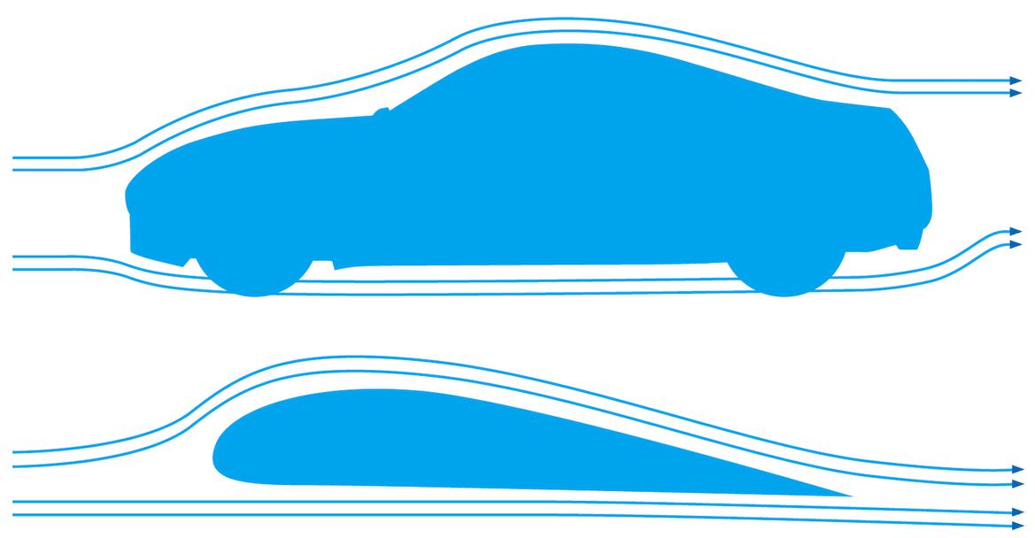
At the end of the day, most street cars resemble wings. What do wings do? Create lift. To improve our lap times, we need to mitigate that lift–and hopefully increase downforce.
What’s wrong with lift? Well, how well do you think an airplane’s tires work at 30,000 feet? Lift removes weight from the car’s contact patch, removing available traction in the process. This is bad, especially if you’re on track.
Of course, OEMs know this, and modern cars are all put through wind tunnels. So why do they build cars with lift? Because they’re not worried about lift, they’re worried about drag. Drag is the amount of force it takes to push a car through the air, and it’s a primary driver of fuel economy in modern cars.
Nissan likely cared way more about reducing drag than it did about increasing downforce when it designed our 350Z. More lift was just an unfortunate side effect of creating a streamlined shape.
Lift vs. Drag and Aerodynamic Efficiency
Now that we’ve introduced lift and drag, we should talk about how intimately related they are. Lift creates drag, and you’ll see many aerodynamic devices marketed with their lift-to-drag ratio in big, bold numbers.
This ratio is a measure of aerodynamic efficiency, and more efficient aerodynamic devices essentially do the same aerodynamic work while wasting less horsepower to overcome drag. A modern Boeing 737 has a very high lift-to-drag ratio, while a paper airplane with flat wings has a very low lift-to-drag ratio.
Oh, and lift can go the opposite direction, too. Fly an airplane upside down, and its wings are actually making downforce. That’s all a race car wing is, which is why you’ll see them marketed with lift-to-drag ratios, too.
What About Downforce?
We’re 550 words into this story about downforce, and all we’ve really talked about is lift. Why? Because the same tools that counteract lift can be made more aggressive until they make net downforce on the car.
Downforce is awesome for race cars: It puts more force on each tire, giving more traction, without adding much mass to the car. A car with 1000 pounds of downforce has the traction of a car that’s 1000 pounds heavier, but it only has to use that traction to accelerate the additional mass of the aerodynamic devices added. Downforce is the closest thing to free lunch in motorsports, especially if it’s accomplished through aerodynamic elements with a high lift-to-drag ratio.
What Can We Do About All This?
Pretty complicated problem, right? We’ve established the basics: Cars are just big wings that make lift and racers add aerodynamic devices like wings, splitters, spoilers, dive planes, wheel wickers, diffusers, flat bottoms and more to counteract lift and make downforce.
But which aerodynamic devices should we pick, and how exactly will each affect our car? Keep in mind that every single aerodynamic change affects every other part of the car, too, a fact that’s well illustrated by the design of those ugly headlights on the front of every Nissan Leaf. Those headlights meaningfully change the airflow around the Leaf’s mirrors, reducing drag and wind noise in the derpy electric car.

Photograph Courtesy Nissan
We need to figure out how to match that level of aerodynamic sophistication in our home garage and plan a comprehensive package of improvements to make our 350Z faster.
Sometimes this is easy–a rule book might restrict what can be done to the point where there’s only one real option for aerodynamic improvement–or sometimes you can look at what other people racing your chassis are running and crib from their notes.
We didn’t see either of these options as particularly useful. NASA’s TT2 rules barely limit aerodynamic improvements, and we didn’t find any 350Zs with well-developed and -documented aero packages in the wild.
Plus, we figured this was an opportunity to learn about a fascinating new world–the world of computational fluid dynamics, better known by its abbreviation, CFD. CFD is essentially a virtual wind tunnel where a computer simulates each air molecule as it interacts with your car, your aerodynamic devices, the road and the other air molecules.
Teams that have taken advantage of modern CFD include every NASCAR effort, every F1 team, every IndyCar team and even Grassroots Motorsports. Yeah, you read that right. Here’s how we put our 350Z into the virtual wind tunnel, what we learned along the way, and how you can use this tool to make your own car faster.
Wind Tunnels vs. CFD
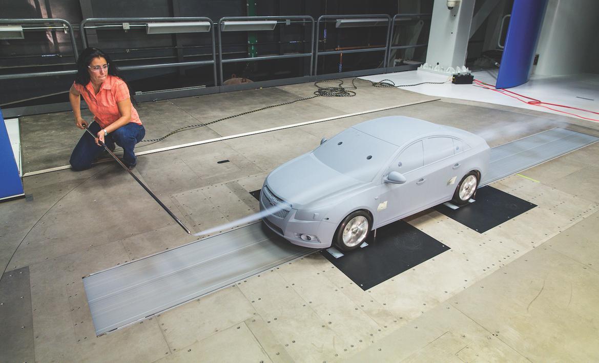
Stop screaming. We hear you. You’re saying, “Go to a wind tunnel! That’s what all the other race cars do when they have questions about aerodynamics!”
Well, not quite. Sure, that was the answer a decade ago. And wind tunnels still have a place in modern motorsports. But more and more, the professional teams are actually using CFD. Why? Multiple reasons. First, wind tunnels are expensive. It takes a rolling road wind tunnel to best the data that CFD computers can spit out, and parking your car on that supersized fan/treadmill combination costs thousands of dollars per hour.
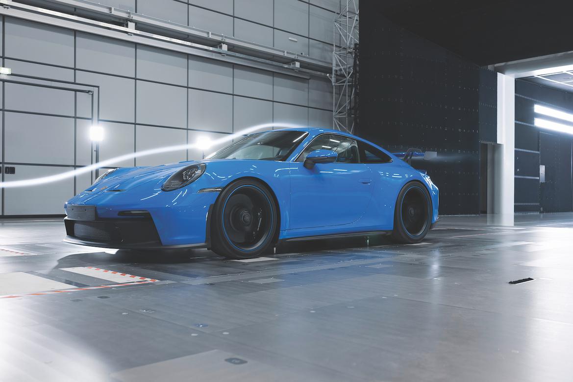
The factories have access to all sorts of aero research, including both scale and full-size wind tunnels. An example of that aero knowledge: how the Nissan Leaf’s headlights direct air around the mirrors. Photography Credits: Courtesy GM (model), Courtesy Porsche (GT3)
Second, wind tunnels require the car’s physical presence. And while that’s not that big of a deal, they also require every aerodynamic configuration to be represented. If you want to test three wing designs and three splitter designs, you’d better buy and bring a functional copy of each–as well as a checkbook to pay for the time you spend in the tunnel changing parts on the car.
CFD, in comparison, doesn’t require taking a car anywhere. It doesn’t require any parts. In fact, testing a different wing is as simple as drawing it onto the 3D model, meaning it allows teams to try more things in more conditions. CFD also allows far better visualization and data capture than a wind tunnel, as instrumenting and measuring each test isn’t even an item on the to-do list. The computer handles all of that automatically.
Finding a Virtual Wind Tunnel
Okay, so CFD is cool, but how do mere mortals like us access it without picking the lock on the Red Bull Racing server room? That question led us to Morlind Engineering, a small firm based just feet from the Panoz race shop next door to Road Atlanta. It specializes in CFD work for aerodynamic companies and for racers just like us, and owner Rob Lindsey agreed to open the hood on each step of the process as the folks there analyzed our 350Z’s aerodynamic performance.
Of course, it does take money to hire Morlind. A CFD analysis package starts at about $4500, though prices vary based on how much you’d like to test and whether you already have a CAD model of your car that can be placed in the tunnel. We think it’s a fair price to pay for what we learned, but let’s not get ahead of ourselves. It’s time for step one: scanning.
How to 3D Scan Your Race Car at Home
The first step of the CFD process? Create a CAD model of the car. That starts with a three-dimensional scan of the car. Morlind offers two ways to do this: by bringing the car to the shop, or by following its step-by-step instructions at home. Since we wanted to keep working on our 350Z in our own garage while the CFD work was completed, we chose to scan our car at home.
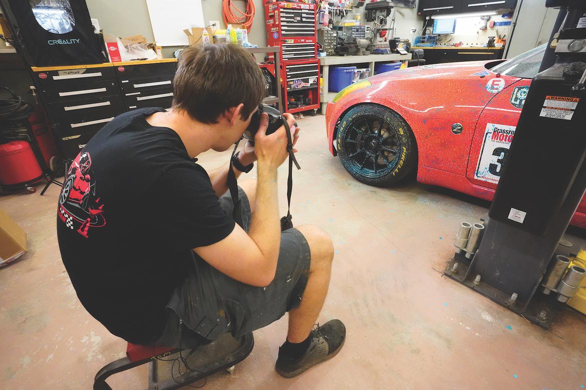
What’s it take to scan a car? Morlind has perfected a method based on photogrammetry, which uses hundreds of photos and a fancy computer algorithm to assemble a scan of the car without any specialized equipment. All you need is a digital camera with a fixed-focal-length lens; we used a 10-year-old DSLR.
Before shooting photos, though, we needed to chalk the car. Computers struggle with reflective surfaces, and sprayable chalk dulls them while easily washing off. It also creates a unique pattern all over the car. By spraying different colors on different sides of our 350Z, we ensured that every square inch would be unique, and the computer wouldn’t have any issues combining the photos into a model of the car.
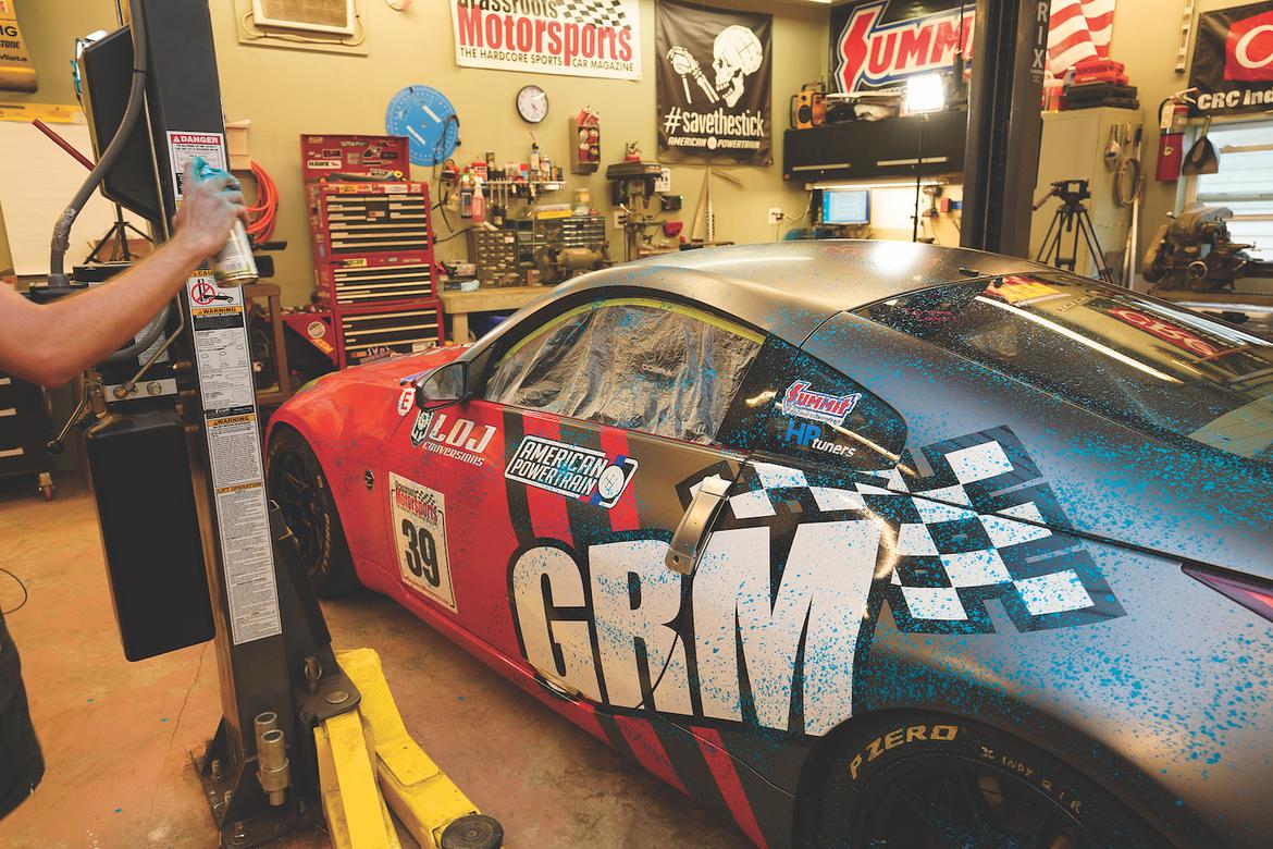
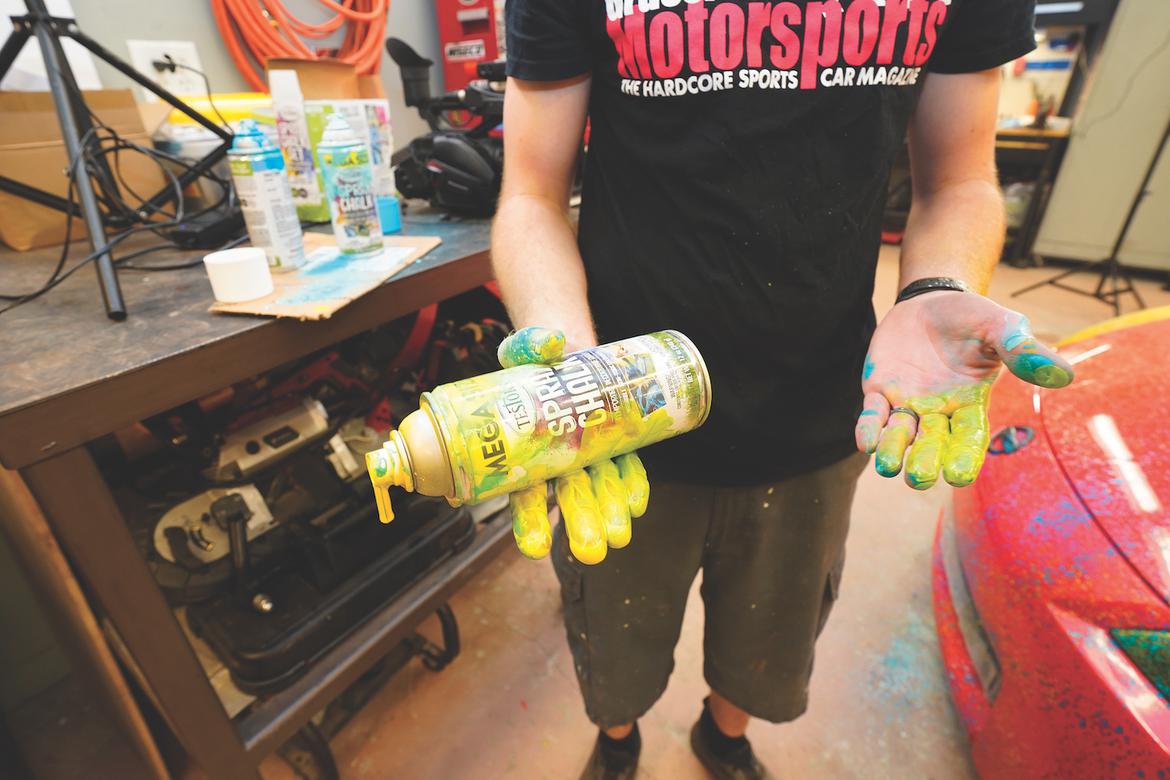

We don’t have the budget for wind tunnel time, but we can still perform aero research via a CFD analysis. The first steps: Cover our LS-swapped Nissan 350Z in chalk and take a lot of photos. Photography Credits: Chris Tropea
Chalk applied, it was time for photos. Morlind’s advice: Shoot 500 to 1000 photos, each perpendicular to the panel being photographed and with even lighting. We circled the car on a ladder, stool and creeper, gathering hundreds of photos of every panel. Then we uploaded our photos, sat back and waited.
How to Create a 3D CAD Model From Your 3D Scan
With our part done, it was time for Morlind owner Rob Lindsey to get to work. It only took a few hours for our car’s 3D scan to appear on his screen, but, as he explained, that was just the tip of the iceberg.
Why can’t the 3D scan go directly to the virtual wind tunnel? Because it’s just a computer-generated mesh in the shape of our 350Z, and it isn’t a surface the computer sees as airtight. To run any CFD analysis, Rob had to turn this scan into a CAD model of the car, complete with spinning wheels and an engine bay.
Think of it this way: The 3D scan generated a file similar to what you’d see if you draped fabric over your car and took its picture. Now it was Rob’s job to build the underlying car represented by that fabric.
Along the way, Rob would also model the bumper openings, engine bay, drivetrain, underside, wheels and more, with the goal of simulating real life as closely as possible. Morlind’s CFD model would simulate airflow over each of these things, and that would take time.
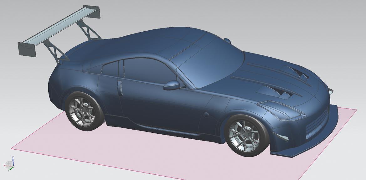
Morlind Engineering used our photos to create a full CAD model of our 350Z. Now we can work on improving the car’s aero profile. Image Courtesy Morlind Engineering
There’s no shortcut for this part of the process, which also represents most of the cost for this CFD work. Morlind usually bills 60 to 100 hours to model a race car. Rob spent approximately 80 hours modeling our 350Z from scratch in Siemens NX, using the 3D scan to guide him as he created every individual plane of the body by hand, down to the rolled fenders we’d done just a few weeks earlier.
The result was amazing: a perfectly accurate 3D model of our 350Z in the computer, complete with the LS swap, radiator, suspension control arms and more. Now it was time for the real magic to begin. We’ll put our car in Morlind’s virtual wind tunnel in the next installment of this series.